OWNER’S MANUAL
POLYURETHANE SPIDER STOOL
MODEL NO. 1990
DESCRIPTION
Lyon Polyurethane Spider Stool is ergonomically engineered
for durability, support, comfort and long wear in tough
environments. Pneumatic lift allows 10″of adjustment while
you are seated. Five-leg base is 25″in diameter, black
powder-coated, welded tubular steel with 18″footring.
Five-leg base ensures maximum stability, especially critical
at high height ranges. Five high-impact, non-marking,
oil-resistant glides withstand harsh environments. Casters
are available as an option.
GENERAL SAFETY INSTRUCTIONS
Do not stand on seat. Stool must be on level surface to
ensure proper stability. Only use stool when fully assembled.
Periodically check fasteners and tighten securely as needed.
Never use stool if it does not perform according to this manu-
al. Warranty may be void if stool is used while damaged.
Immediately call and report any problems (see How to Order
Repair Parts) and always give the serial number from label
under seat.
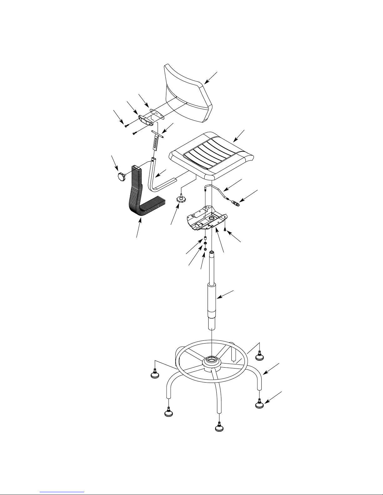
ASSEMBLY
1. Unpack stool. Check all parts against parts list before
beginning assembly. Allow parts to warm to room temper-
ature prior to assembly.
2. Turn base (Key No. 2) upside down. Insert the five glides
(Key No. 1) into the end of the base spokes. Turn base
right side up.
3. Insert pneumatic lift (Key No. 3) into base, tapered end
down. Secure the lift assembly by applying a little down-
ward pressure. Remove yellow plastic cap from end of lift
assembly.
4. Install seat (Key No. 20) on top of lift. Align hole in control
assembly (Key No. 7) with top of lift. Push down on seat to
insert firmly together. Underneath the seat on right side is
a handle to adjust height of lift.
5. Slide backstem bellows (Key No. 12) over lower backstem
(Key No. 13). Flat portion of bellows must be positioned
towards back of backrest (Key No. 19).
6. Slide lower backstem (Key No. 13) into slot at back of con-
trol assembly. Slide backstem until push button locks in
control. Remove knob with cone point (Key No. 11) from
parts bag. Thread knob into control and tighten to secure
lower backstem.
7. Slide upper backstem (Key No. 17) with backrest into
lower backstem. Tighten knob with flat point (Key No. 14)
to secure backrest in place.
8. Make final stool adjustments following instructions on
page 4.
MAINTENANCE
The pneumatic lift is permanently lubricated at the factory
and needs no further lubrication. Never lubricate the
pneumatic lift. This could damage the lift and void your
warranty.
Do not remove clip from bottom of lift. Call for immediate
assistance if clip is missing or damaged. Clean polyurethane
seat and backrest with soap and water. To repair cuts, apply
a few drops of quick drying glue in the cut and press the
sides together until glue sets.
PART NO. 08128.00 Sold by LYON WORKSPACE PRODUCTS, P.O. Box 671, AURORA, IL 60507 USA DECEMBER 2007
Save This Manual For
Future Reference
HOW TO ORDER REPAIR PARTS
When ordering repair parts or reporting problems, always give the
following information:
NAME OF ITEM MODEL NUMBER
Polyurethane Spider Stool 1990
PART DESCRIPTION PART NUMBER
All parts listed may be ordered from your local Lyon Dealer or
Lyon Workspace Products, P. O. Box 671, Aurora, IL 60507
800/323-0082 or 630/892-8941