manuals.online logo
Brands
  1. Home
  2. •
  3. Brands
  4. •
  5. Lyon
  6. •
  7. Indoor Furnishing
  8. •
  9. Lyon Maclnnes MK6 User manual

Lyon Maclnnes MK6 User manual

This manual suits for next models

1

Other Lyon Indoor Furnishing manuals

Lyon Sit/Stand User manual

Lyon

Lyon Sit/Stand User manual

Lyon 1990 User manual

Lyon

Lyon 1990 User manual

Lyon OBELISK User manual

Lyon

Lyon OBELISK User manual

Lyon LPP0004 User manual

Lyon

Lyon LPP0004 User manual

Popular Indoor Furnishing manuals by other brands

Regency LWMS3015 Assembly instructions

Regency

Regency LWMS3015 Assembly instructions

Furniture of America CM7751C Assembly instructions

Furniture of America

Furniture of America CM7751C Assembly instructions

Safavieh Furniture Estella CNS5731 manual

Safavieh Furniture

Safavieh Furniture Estella CNS5731 manual

PLACES OF STYLE Ovalfuss Assembly instruction

PLACES OF STYLE

PLACES OF STYLE Ovalfuss Assembly instruction

Trasman 1138 Bo1 Assembly manual

Trasman

Trasman 1138 Bo1 Assembly manual

Costway JV10856 manual

Costway

Costway JV10856 manual

moss DESIGN Caisson Credenza Assembly instructions

moss DESIGN

moss DESIGN Caisson Credenza Assembly instructions

Aquaglide FULL DECK 15.0 owner's manual

Aquaglide

Aquaglide FULL DECK 15.0 owner's manual

AREBOS AR-HE-SW30 user manual

AREBOS

AREBOS AR-HE-SW30 user manual

Till-Hilft Fulda 87005.330 Assembly instructions

Till-Hilft

Till-Hilft Fulda 87005.330 Assembly instructions

Twoey Outside 2010 quick start guide

Twoey Outside

Twoey Outside 2010 quick start guide

Hettich Easys 200 operating instructions

Hettich

Hettich Easys 200 operating instructions

The bedboss RELAX 404 Series owner's manual

The bedboss

The bedboss RELAX 404 Series owner's manual

Oeseder Möbelindustrie Bern 991 720 Assembly instructions

Oeseder Möbelindustrie

Oeseder Möbelindustrie Bern 991 720 Assembly instructions

Costway HW68469 user manual

Costway

Costway HW68469 user manual

Next ALIX A27743 Assembly instructions

Next

Next ALIX A27743 Assembly instructions

BROSA Hans Assembly guide

BROSA

BROSA Hans Assembly guide

Prodigg MINIKA PBA015T-FUR installation manual

Prodigg

Prodigg MINIKA PBA015T-FUR installation manual

manuals.online logo
manuals.online logoBrands
  • About & Mission
  • Contact us
  • Privacy Policy
  • Terms and Conditions

Copyright 2025 Manuals.Online. All Rights Reserved.

lyon.co.uk/user-instructions
Code
LMK6-ST
CE, 93/42/EEC Class 1, 2007/47/EC
For more detailed user
information and to
download a PDF copy
of these instructions
follow the link above or
scan the QR code with
your smart phone
USER INSTRUCTIONS
Lyon Equipment Limited
Units 3-7,Tebay Business Park,
Old Tebay,
Penrith,
Cumbria, United Kingdom,
CA10 3SS
Tel: +44 (0) 15396 24040
Email: info@lyon.co.uk
Web: lyon.co.uk
© Lyon Equipment 2019
UI_LMK6-ST_16347
5055835 607820
MacInnes MK6 stretcher
UI_LMK6-ST_16347.indd 1 18/04/2019 10:57:39
Downloaded from lyon.co.uk
2
This information to be read and
kept for the lifetime of the product
in conjunction with the Lyon
General User Instructions.
All users must have appropriate training,
knowledge and experience of casualty
care, casualty handling and work and
rescue at height, or be working under
the direct supervision of such a person.
Note: In these instructions the LYON
MACINNES MK6 STRETCHER is
referred to as ‘the stretcher’.
Working Load Limit (WLL)
4-point lift suspension, carrying via
handles - 136 kg
6 point horizontal suspension via 6
suspension rings - 272 kg
6 point vertical suspension via 6
suspension rings - 272 kg
Certication
CE, 93/42/EEC Class 1, 2007/47/EC
Nomenclature of parts
Stretcher
1. Top tube
2. Skid
3. Bed
4. Strengthening
plate
5. Damper sleeve
6. Foam pad
7. Handle
8. Joint locking
toggle bolt
9. Joint locking pin
10. Head suspension
point
11. Middle suspension
point
12. Foot suspension
point
13. Hinge brackets
for head guard
14. Head guard shock
cord hook
15. Handle locking
pin
16. Casualty securing
strap
17. Wheel locating
saddle
Pack frame
18. Frame
19. Shoulder harness
20. Belt
21. Mounting pegs
22. Alloy channel
Headguard (accessory)
23. Drop pin latch
24. Shock cord
25. Mesh
6-point lifting bridle (accessory)
26. Suspension ring
27. Wire leg
28. Karabiner
29. Maillon Rapide
Wheel unit (accessory)
30. Wheel
31. Securing pin
32. Frame
6-point lifting bridle
(accessory)
27
28
26
29
UI_LMK6-ST_16347.indd 2 18/04/2019 10:57:39
Downloaded from lyon.co.uk
3
Stretcher
17
16
15
14
13
12
11
10
9
8
7
6
5
4
3
2
1
UI_LMK6-ST_16347.indd 3 18/04/2019 10:57:40
Downloaded from lyon.co.uk
4
Pack Frame (accessory)
18
19
20
21
22
Wheel unit (accessory)
30
32 31
Headguard (accessory)
25
24
23
UI_LMK6-ST_16347.indd 4 18/04/2019 10:57:40
Downloaded from lyon.co.uk
5
Limitations
The stretcher has passed manufacturer’s
test requirements with a test mass
equivalent to the maximum intended
combined load (casualty + stretcher
+ medical equipment) of 272 kg when
suspended by all six suspension points.
When working with loads over 100 kg,
take care not to exceed the load-
bearing capacity of other components
in the system.
The stretcher must not be used for
casualties with spinal injuries without
additional spinal support e.g. vacuum
mattress, spine board.
Due to the nature of this product it is
not possible to make it personal issue.
Use
This stretcher is for rescue and rescue
training purposes only. It is used
to transport an injured or stranded
casualty from an area that is difcult
to access, either by multi-person
manual extraction or in conjunction
with a lifting, lowering or suspension
system within the guidance set out in
these instructions and by trained and
competent users.
All other uses are forbidden without the
written approval of Lyon Equipment Ltd.
The stretcher must not be used in a fall
arrest system.
The stretcher may be used in
conjunction with compatible items
of personal fall protection equipment
of suitable specication, with due
consideration to the limitations of each
individual piece of equipment in the
safety chain.
A minimum of two personnel are
required to transport an empty
stretcher. Additional trained personnel
will be needed for movement once
loaded.
Planning a rescue
Taking into consideration the casualty’s
injuries, environmental hazards and
the intended extraction system, assess
whether this stretcher is suitable for the
particular application.
Before commencing the rescue, a plan
must be in place as to how to deal with
any emergencies which may arise during
the rescue.
The time that a casualty is held in a
vertically orientated stretcher must be
kept as short as possible to minimise
risks to respiration and circulation
(suspension intolerance).
The casualty should spend the minimum
time possible on the stretcher. Extended
periods of immobility increase the risk
of pressure sores.
Assembly of the stretcher
Ensure the two joint sections are clean
and undamaged.
Place the foot half vertically on its end,
joint uppermost and underneath surface
towards you. Either lean it against a
support, or obtain an assistant to hold
it steady.
UI_LMK6-ST_16347.indd 5 18/04/2019 10:57:40
Downloaded from lyon.co.uk
6
Remove the two joint locking pins from
the top tubes.
Lower and engage the top half of
the stretcher, joint downwards and
underneath surface towards you,
ensuring that no debris becomes
trapped between the two halves.
Continue to stand facing the underneath
surface.
Slot the two sections together until
there is a short gap, then unscrew the
knurled nuts of the toggle bolts to their
full extent and angle them upwards so
that they can drop into the slots in the
opposite brackets once the stretcher
halves are pushed together.
Push the stretcher halves together,
ensuring that the two captive nuts on
each skid face t into the two drilled
holes on the matching joint face,There
must be no gap between the two skid
joint faces.
Tighten rmly the two knurled nuts on
each toggle bolt.
TOGGLE BOLTS AND KNURLED
NUTS MUST ONLY BE
TIGHTENED BY HAND - DO
NOT USE TOOLS.
Insert the two joint locking pins into the
top tubes. Ensure they are fully inserted
and the spring bail closed over the tube.
Place the stretcher on the ground and
prepare the casualty for loading.
Deploy the head guard and/or handles,
if required.
Installing/removing the head guard
Before tting, ensure the casualty,
casualty packaging and any medical
equipment will not contact or interfere
with the head guard.
Ensure the head guard, stretcher top
tube and hinge brackets are clear of
debris, snow, mud etc. Clean if necessary.
Place the head guard onto the stretcher,
hinge tubes adjacent to stretcher hinge
brackets.
With the drop nose pin latch parallel
to the pin body, insert each pin through
its adjacent stretcher hinge bracket and
head guard hinge tube.
Rotate the drop nose pin latch through
90° and push all the way across.The
drop nose pin latch in this position
prevents accidental removal of the pin.
UI_LMK6-ST_16347.indd 6 18/04/2019 10:57:41
Downloaded from lyon.co.uk
7
Connect each shock cord end hook to
its adjacent shock cord hook on the
stretcher.
The head guard is now tted.
Remove the head guard by reversing the
above procedure.
CAUTION - ALWAYS MAINTAIN
A POSITIVE HOLD ON
THE SHOCK CORD WHEN
ATTACHING OR RELEASING.
Extending / retracting the
transport handles
Handles are provided on all four
corners of the MK6 stretcher to assist
in a manual carry.
Handles are extended into the transport
position by removing the captive handle
locking pin and withdrawing the handle
until it reaches the internal stop.The
handle locking pin is then re-inserted.
Repeat for each of the handles.
CHECK ALL FOUR LOCKING
PINS ARE INSERTED
CORRECTLY BEFORE LIFTING
THE STRETCHER.
Store the handles by reversing the
above procedure.
Securing the casualty in the
stretcher
Before securing the casualty in the
stretcher, consider any medical
conditions and take care to ensure
the casualty is not further injured by
poor tting, trapping parts of the body,
adjustment of straps, or by displacement
of straps during the rescue.
Do not allow the stretcher or any
components to come into contact
with any open wounds. Ensure that the
casualty is not endangered by contact
with other components of the rescue
system, for example a bridle connector
striking the head of the casualty during
an unintended incident such as a short
fall.
Place the stretcher in a secure and
stable position, ideally on a at area with
access on all sides.
Undo the casualty securing strap
buckles and extend each strap to
its maximum length. Lay each strap
outwards from the bed, ensuring that no
strap is trapped under the stretcher.
Lift buckle to loosen
Prepare the bed of the stretcher,
ensuring that any necessary casualty
packaging or medical equipment is in
place and will not interfere with casualty
loading.
Load the casualty onto the stretcher
bed, using a medically approved
movement technique.
UI_LMK6-ST_16347.indd 7 18/04/2019 10:57:41
Downloaded from lyon.co.uk
8
Complete the application of any
treatment, packaging or medical
equipment which is required.
Bring the ends of each casualty securing
strap over the casualty in line with their
respective buckle half.
Connect the strap buckles by inserting
the male part into the female part until
they lock together.
Buckles may be tightened by pulling on
the slack end of the strap, and loosened
by tilting the buckle backwards whilst
pulling the strap back through the
buckle.
Pull to tighten
Particular care should be taken when
securing the casualty in the stretcher for
vertical raising and lowering.
DO NOT OVERTIGHTEN THE
STRAPS – INJURY MAY OCCUR.
Any excess webbing may be folded and
placed under the band of elastic.
It is essential to regularly check
fastening and adjustment elements
during use.
If at any stage the casualty shows signs
of distress or potential injury from use
of this stretcher cease use immediately
and review its suitability and/or
adjustment.
Buckles may be released by slackening
the webbing through the adjuster
and then pushing both brass levers
simultaneously towards the adjuster.The
buckle will then release.
Disassembly of the stretcher
Lower and secure the head guard in the
transport position.
Store the transport handles.
Place the stretcher vertically on its
foot end, underneath surface towards
you. Either lean it against a support, or
obtain an assistant to hold it steady.
Starting on either side, loosen the
knurled nuts on each toggle bolt.
Unscrew the knurled nut on the toggle
bolt to its full extent and angle each
upwards so that they can lift out of the
slots in the opposite brackets.
Release and remove the joint locking
pins.
Lift off the top half of the stretcher and
place on the ground.
Place the bottom half of the stretcher
on the ground.
Ensure that the knurled nuts on the
toggle bolts are tightened on their
respective brackets, so the thread has
protection from the bracket when
transporting the stretcher half, and that
a minimum of thread protrudes.
Tidy away any casualty straps and
prepare the pack frames for transport
of the stretcher halves.
UI_LMK6-ST_16347.indd 8 18/04/2019 10:57:41
Downloaded from lyon.co.uk
9
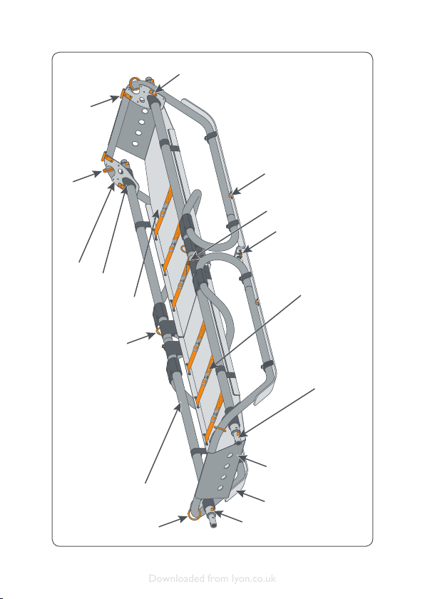
Transport of the dismantled
stretcher
A minimum of two people are required
to transport an empty stretcher. If split
into two sections for transport, each
section may be carried ‘rucksack style’
using the individual detachable pack
frames (accessory).
The pack frames may also be used as
carrying yokes when clipped to the
stretcher handles, to assist in transport
of the loaded stretcher.
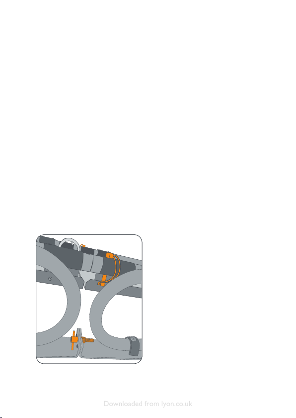
The pack frame ts onto the stretcher
by placing the edge of the stretcher bed
into an alloy channel at the base of the
pack frame.This enables two alloy pegs
to enter two holes in the stretcher bed.
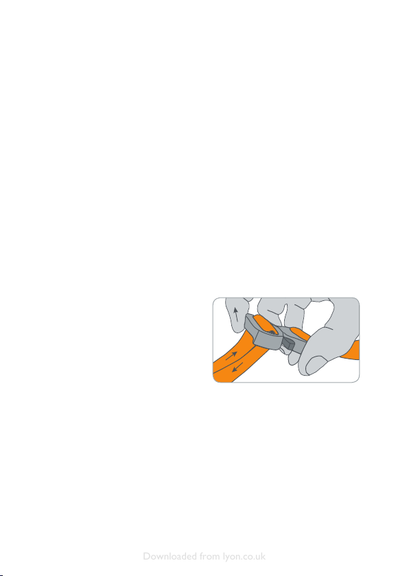
The pack frame is locked in place by
tensioning the shock cord round the
frame and attaching the hooks through
the holes in the alloy pegs.
TAKE CARE WHEN TENSIONING
THE SHOCK CORD THAT YOUR
FACE IS NOT IN LINE WITH THE
TENSIONED SHOCK CORD -
ACCIDENTAL RELEASE MAY
CAUSE INJURY.
Each stretcher section weighs approx.
9 kg. Assistance with picking up and
placing the stretcher section on the
back, and adjusting the shoulder straps
to provide a secure and stable t, is
strongly recommended.
Be aware of projections on the frame –
ensure there is adequate space around
the person carrying the stretcher
section to prevent accidental contact.
Carrying the loaded stretcher
Be aware that a loaded stretcher
(stretcher + casualty + medical
equipment) may weigh up to 136 kg.
Multiple personnel are required to
lift and transport a loaded stretcher.
Stretcher carriers should regularly
change position to reduce fatigue.Take
extra care when lifting and lowering
the loaded stretcher – training and
coordinated action is essential.
There are many methods of positioning
personnel around a stretcher to enable
it to be transported.The maximum
practical number of personnel who can
effectively share the load is eight.
Sliding the stretcher
The stretcher may be slid on its skids
over smooth surfaces. Avoid abrasive
surfaces which could damage the skids;
also avoid rocks, stumps, branches and
other hazards that could penetrate the
stretcher bed or cause discomfort or
injury to the casualty.
Lifting, lowering or suspension of
the stretcher via a rescue system
Rope rescue system anchors must be
unquestionably reliable, orientated
appropriately and of sufcient strength
for the anticipated load. Ensure all
other components in the system are
compatible and of sufcient strength.
The use of a two rope system (main
and safety) is recommended. All such
systems should incorporate a ‘fail to
safe’ principle.
UI_LMK6-ST_16347.indd 9 18/04/2019 10:57:41
Downloaded from lyon.co.uk
10
Stretcher connections to the rope
rescue system must be made via the
ALL six of the suspension points, using
suitable locking connector(s), the MK6
stretcher lifting bridle accessory or by
tying in directly.
Ensure that the connector(s) selected
have sufcient gate opening clearance
and volume to accommodate the
suspension points.
Vertical raise or lower –
Recommended system
connections
Rigging of each rope system begins at
the foot end of the stretcher.
A gure of eight knot is tied in the
end of one rope and secured to one
foot suspension point via a suitable
connector.The rope is brought to
the middle suspension point on the
same side and secured to that point
via a suitable connector using a clove
hitch.The rope continues to the head
suspension point and is secured to that
point via a suitable connector using an
Alpine Buttery knot. Each head end
connection point has two rings,
clip into both rings with the same
connector.
The foot, middle and head connectors
must be orientated towards the head of
the stretcher (in line with the expected
force) when tensioning the rope
between them.
A second Alpine buttery knot is now
tied in the rope and connected into the
opposite head end suspension point via
a suitable connector.The knot position
and length of the closed loop of this
knot are adjusted to create a Y shaped
connection to the stretcher.The angle
between the two arms of the Y must
not exceed 90°.
The above connection sequence is
repeated for the second rope, beginning
at the opposite foot suspension point,
connecting to the middle suspension
point and connecting into the same
two connectors at the head suspension
points.
CONNECTORS MUST ALWAYS
BE ATTACHED WITH THE GATE
FACING THE BED OF THE
STRETCHER. GATE OUTWARDS
= DANGER
Horizontal raise or lower
- Recommended system
connections
Read and understand the product
instructions for the selected stretcher
lifting bridle.
The six legs of the stretcher bridle
must be connected to the designated
colour-coded suspension points on the
stretcher, using the captive connectors
tted to them. Care should be taken
to verify that the connectors’ locking
mechanism is operating correctly.
CONNECTORS MUST ALWAYS
BE ATTACHED WITH THE GATE
FACING THE BED OF THE
STRETCHER. GATE OUTWARDS
= DANGER
UI_LMK6-ST_16347.indd 10 18/04/2019 10:57:41
Downloaded from lyon.co.uk