Lyon OBELISK User manual

lyon.co.uk/user-instructions
Code
LPP0003
For more detailed user
information and to
download a PDF copy of
these instructions and a
Declaration of Conformity
follow the link above or
scan the QR code with
your smart phone
USER INSTRUCTIONS
Lyon Equipment Limited
Units 3-7,Tebay Business Park,
Old Tebay,
Penrith,
Cumbria, United Kingdom,
CA10 3SS
Tel: +44 (0) 15396 24040
Email: info@lyon.co.uk
Web: lyon.co.uk
© Lyon Equipment 2019
UI_LPP0003_19092
5055835 608100
OBELISK
EN 795:2012 Type B
CEN/TS 16415:2013 Type B
UI_LPP0003_19092.indd 1 04/04/2019 11:28:39
Downloaded from lyon.co.uk

2
This information to be read and
kept for the lifetime of the product
in conjunction with the Lyon
General User Instructions.
Quality assurance
Quality management system
assessed and certied as meeting the
requirements of ISO 9001.
Certication
When used for a single person load:
CE 0598, EN 795:2012 Type B “Personal
fall protection equipment. Anchor
devices”.
When used for a two person load:
CEN/TS 16415:2013 Type B “Personal
fall protection equipment – Anchor
devices – Recommendations for anchor
devices for use by more than one
person simultaneously”.
When used for rescue or a two person
load, this item is not classed as PPE
and is not covered by PPE Regulation
2016/425.
Approved bodies
EU Type-examination for Regulation
2016/425 by:
Notied Body No. 2777
SATRA Technology Europe Ltd,
Bracetown Business Park, Clonee,
Dublin, D15 YN2P, Ireland.
Controlling the manufacturing:
Notied body No. 0598
SGS Fimko Oy, P.O. Box 30
(Särkiniementie 3),
00211 HELSINKI, Finland.
Working Load Limit (WLL)
Please note that the WLL refers to the
total combined load on the OBELISK.
The combined load must not exceed
this amount.
Where dynamic loads are envisaged, the
WLL may be up to 100 kg for a single-
user (EN 795:2012) and 200 kg for
two-users (CEN/TS 16415:2013).
Where only static loads are applied, the
WLL may be up to 272 kg.
The WLL specied above apply when
used in congurations described in
these User Instructions, with loads
suspended from the anchor point and at
90° to the footprint. Alternative rigging
layouts, terrain and environmental
conditions may apply forces in directions
that reduce the stability of the OBELISK.
In such circumstances, the WLL must be
decreased. Resultant forces that extend
beyond the footprint of the OBELISK
can cause overturning.
Ultimately, the user of the OBELISK is
responsible for determining theWLL
of the OBELISK based on the specic
circumstances of use and the factor of
safety applied. Users may reduce the
WLL.The user must never exceed the
WLL.
Breaking load
For a single person load:
EN 795:2012 requires a minimum
breaking strength of 12 kN.
For a two person load:
CEN/TS 16415:2013 requires a
minimum breaking strength of 13 kN.
UI_LPP0003_19092.indd 2 04/04/2019 11:28:39
Downloaded from lyon.co.uk

3
Warning
Where accessories are available refer to
the user instructions supplied with the
accessories.
Always inspect the OBELISK before use.
Refer to instructions for inspection.
A damaged, incorrectly loaded or
overloaded OBELISK could fail, causing
damage, injury or death.
When carrying out work at height
maintain an appropriate exclusion zone.
Remain vertically below the anchor
point to minimise the risk of a
pendulum fall which may apply loads
outside the footprint of the OBELISK,
shock load it or destabilise it.
The OBELISK will transmit any force
applied directly to the structure in the
direction in which it is applied.The
OBELISK will attempt to align with
any applied force, and may move if the
load is not applied perpendicular to the
structure.
Never adjust any part of the OBELISK
once it has been deployed and is in use.
Nomenclature of parts
1. Top Beam
2. Carriage(s)
3. Swivel Anchor
Point
4. Locking Pin
5. Leg Carrier
6. Guy Line
Attachment Point
7. Leg section (top/
middle/bottom)
8. Foot
9. Spike
10. Leg Restraint
Strap Attachment
Point
11. Leg Restraint
Strap
12. Foot lock
11
7
8
12
9
10
12
3
5
6
6
7
4
UI_LPP0003_19092.indd 3 04/04/2019 11:28:42
Downloaded from lyon.co.uk

4
Use
The OBELISK is intended to provide an
elevated anchor point(s) for combined
loads not exceeding 272 kg, within the
limits and restrictions dened by these
User Instructions.
For single-user use, the OBELISK is
Personal Protective Equipment, and
may be a personal issue item. For two
simultaneous users or during rescue,
the OBELISK is not Personal Protective
Equipment. Please note, for all uses, the
OBELISK is NOT lifting equipment.
Always know the weight of the intended
load before using the OBELISK. Do not
overload the OBELISK.
Under normal operating conditions, the
OBELISK will not show any obvious
deection.
Always ensure that the surface the
OBELISK is to be used upon is capable
of withstanding the foreseeable loadings
applied by the OBELISK.The surface
on which the OBELISK is placed may
dramatically reduce both theWLL and
the stability of the OBELISK, e.g. if there
are overhangs, undercuts, voids, slippery
and/or sloping surfaces, free owing
solids.
Always ensure the OBELISK is of a
suitable size, shape and conguration for
the intended use.
The OBELISK can be used with
differential leg adjustments in any
combination, e.g. short front legs and
long back legs, or short side legs and
long side legs. Ensure that the upper
surface of the Top Beam is level in the
horizontal planes.
NOTE: It is not the intention of
these user instructions to describe
the numerous alternative systems
that may be connected to the
OBELISK. It is the responsibility
of the user to check compatibility
with the other elements in the
safety chain before using this
product.The performance of the
elements of the safety chain must
not be compromised when the
OBELISK is installed and in use.
Assembling the OBELISK
Assemble the OBELISK a safe distance
from any fall hazard.
Users are responsible for ensuring their
own safety whilst assembling, erecting
and using the OBELISK.
UI_LPP0003_19092.indd 4 04/04/2019 11:28:42
Downloaded from lyon.co.uk

5
The OBELISK may be assembled as
follows:
1. Adjust all legs to the expected
operating height and secure with the
attached locking pins. Do not over
extend the legs beyond the warning
signs.
NOTE:To adjust the bottom leg section
remove the bottom Locking Pin.To
adjust the middle leg section, remove
both Locking Pins.
2.After assessing the proposed location,
select the foot option most appropriate
for the surface (Foot or Spike). Select
Spikes when on uneven surfaces. When
feet are used, ensure the feet are at on
the surface.
3. Correctly orientate one Leg Carrier
to allow insertion of the Top Beam.
Slide the Top Beam into the Leg Carrier,
adjust the Top Beam to the expected
width position and secure with the
attached Locking Pin.
4. Slide the Carriage onto the Top
Beam, adjust to the expected position
(normally the centre of theTop Beam)
and secure with the attached Locking
Pin. No more than two Carriages are
permitted on the Top Beam.
5. Correctly orientate the second Leg
Carrier to allow insertion of the Top
Beam. Slide the Leg Carrier onto the
Top Beam, adjust the Leg Carrier to
the expected width position and secure
with the attached Locking Pin.
6.At this point it may be appropriate to
attach the required rigging or personal
fall protection equipment to the Swivel
Anchor Point(s). Be aware that once
the OBELISK is raised into its working
position these points may be out of
reach.
7. Using additional personnel, if
required, raise the OBELISK upright
by lifting the two legs positioned away
from the ground and then raising the
head assembly upwards, allowing the
OBELISK to pivot on the lower feet into
an upright position.
TAKE CARE - MANUAL
HANDLING AND ENTRAPMENT
RISK DURING THIS OPERATION.
IFTHE HEIGHT OFTHE OBELISK
REQUIRES ADJUSTMENT ONCE
IN THE UPRIGHT POSITION,
ALWAYS HOLD THE LEG
SECTIONS ABOVE THE LEG
BEING ADJUSTED TO PREVENT
COLLAPSE WHEN REMOVING
THE LOCKING PIN(S).
8. Re-check all connections and Locking
Pins are securely tted before moving
the OBELISK into the working position.
9. Move the OBELISK into the working
position, whilst maintaining the safety
of the users.
MAX
DANGER
MAX
DANGER
UI_LPP0003_19092.indd 5 04/04/2019 11:28:42
Downloaded from lyon.co.uk

6
10. Position the legs so that the
indicators on each Leg Carrier line up
with the leg.This ensures the OBELISK
is set up with the legs at the approved
angle.
11. Install the Leg Restraint Straps (see
section Leg Restraint Straps). Ensure
the straps are adjusted so that all slack
is removed.Where undulations or
obstructions on the worksite surface
prevent a clear path for the Leg
Restraint straps the relevant straps must
be adjusted such that the stability of the
OBELISK is maintained throughout the
activity.Where the strap is forced over
an object causing the strap to raise one
leg off the surface, the OBELISK must
be repositioned.
The OBELISK must never be used
without all four Leg Restraint Straps
correctly tted and adjusted.
Leg Restraint Straps
Leg Restraint Straps are essential for
the structural stability of the OBELISK.
They must be used at all times, in all
congurations.
The ultimate load capacity of the
OBELISK depends on the ability to
secure the feet against movement by
correct use of the Leg Restraint Straps.
In addition to using the Leg Restraint
Straps, it may be appropriate to securely
attach the feet to the surface, e.g.
concrete slab, to prevent movement of
the OBELISK. Direct attachment of the
feet must not be used as a substitute
for correct OBELISK placement (risk of
overloading).
To attach the Leg Restraint Strap, clip
one of the sewn-in quick links onto
the Leg Restraint Strap Attachment
Point on one leg. Extend the strap via
the adjustment buckle and attach the
second quick link onto the Leg Restraint
Strap Attachment Point on the second,
adjacent leg (see gure below). Do not
attach diagonal facing legs together.
Repeat the process until all legs are
linked in a rectangle.
Grasp the tail end of the webbing
exiting each adjustment buckle and
pull, tightening the strap to remove any
slack.Tighten all four straps evenly to
maintain a rectangular foot and ensure
the OBELISK is set up with the legs at
the approved angle (see 10.).
UI_LPP0003_19092.indd 6 04/04/2019 11:28:43
Downloaded from lyon.co.uk

7
Guy Line Attachment Points
When used as described above, guy
lines are not required. However, in some
circumstances, the user may wish to
maintain the stability of the OBELISK
by xing guy lines to the identied Guy
Line Attachment Points. Guy lines must
not be used as a substitute for correct
OBELISK placement.
Suitable EN 362 locking connectors
must be used to attach the guy line to
the Guy Line Attacment point.
Do not attach any part of the safety
system to the Guy Line Attachment
Points.
Attachment of personal fall
protection equipment
Only attach the rigging or personal
fall protection equipment to a Swivel
Anchor Point using a compatible
EN 362 connector.
No more than two Carriages are
permitted on the Top Beam.
Storage and transport
A storage and transport bag is available
for the OBELISK.
It is recommended that the OBELISK is
stored, clean and dry when not in use –
see maintaining your equipment.
The total weight of the OBELISK is
21 kg. It should be classed as a two
person load when transporting manually.
The accessory transport bag is provided
with a number of carrying handles.
Transport bags are not rated as lifting
accessories - do not use the handles for
lifting, lowering or suspending the bag
and its contents at height.
Inspection
The OBELISK should be subject to:
• Pre-use checks
• Thorough inspections (at least once
every 6 months)
• Interim inspections (as appropriate)
The checks should be undertaken in
good light. Any item showing any defect
should be withdrawn from service
immediately.
If in any doubt as to the condition of
the product, it should be withdrawn
from use immediately and not used
again unless conrmed by a competent
person that it is acceptable to do so.
It is recommended the OBELISK is
marked with the date of the next or last
inspection.
Check that any labels and markings are
still intact and readable.
The OBELISK and any accessories
should be checked for signs of
overloading and damage including
wear, corrosion, cracking, weld failure,
abrasion or deformity - list not
exhaustive.
UI_LPP0003_19092.indd 7 04/04/2019 11:28:43
Downloaded from lyon.co.uk

8
Metal items - Leg Carriers,Top
Beam, Carriage, Spike, Feet
inspection
Check for signs of overloading and
damage including wear, corrosion,
cracking, weld failure, abrasion, sharp
edges or deformity. Pay special attention
to the anchor points and all welded
joints.
Ensure the Swivel Anchor Point
functions correctly and is free from
damage.
Ensure there are no sharp edges or
burrs on the Guy Line Attachment
Points. Any burrs or sharp edges may
be removed with the use of emery
cloth.
Assemble the Leg Carriers,Top Beam
and Carriage. Check the individual
sections slide without binding or
excessive play. Locking pins should
t without force in every adjustment
position.
Metal items – Leg inspection
Ensure that the legs are not split,
deformed, corroded or cracked.
The individual sections should slide
without binding or excessive play.
Locking pins should t without force in
every adjustment position.
Check the leg hinge assembly (bolt,
nut, washers) for security.The hinge
assembly should allow movement
without binding or excessive play.
Check the security and function of the
Leg Restraint Attachment Point, Feet
and Spikes.
Metal Items - Locking Pin
inspection
Check that release button moves freely
and that locking detent balls move in
and out when the release button is
operated.
Check that the Locking Pin is not bent
or dented by installing the Locking Pin
into a pin placement; it should move
freely in and out of the placement whilst
the release button is depressed.
Check Locking Pin security in each
pin placement by attempting to pull
the locking pin out of the placement
without depressing the release
button; if removal is possible without
depressing the release button, do not
use and quarantine the Locking Pin
and leg immediately. Retire defective
component(s).
UI_LPP0003_19092.indd 8 04/04/2019 11:28:43
Downloaded from lyon.co.uk

9
Figure shows left pin in good working
condition.The right pin should be
retired due to wear and detent pins not
properly working.
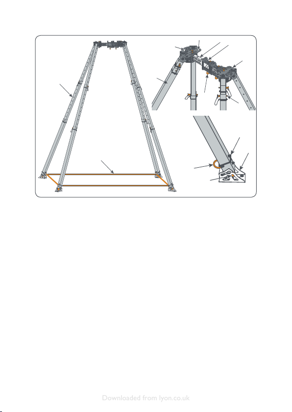
Textile items - Leg Restraint
Straps
The Leg Restraint Strap must be
complete with all end connections, and
must fully adjust and lock over its full
range of adjustment.
Check the webbing visually and by
passing the straps slowly through the
hands to detect damage, e.g. cuts in
the edges of the webbing, abrasion,
cuts across the face of the webbing,
softening or hardening of bres,
ingress of contaminants, broken, cut
and worn threads in the stitching. Pay
particular attention to areas where the
webbing is in contact with connectors,
buckles and the Leg Restraint Strap
Attachment Point. Check the webbing
for discolouration, which could be the
result of chemical or UV damage.
The metallic elements should be
inspected for correct function, signs
of overloading and damage, e.g. wear,
corrosion, cracking, weld failure,
abrasion, sharp edges, deformity.
Any of these defects may affect the
performance of the OBELISK.
Lubrication
All leg hinge assemblies and Locking Pins
should be lightly lubricated after each
use. Use a liquid lubricant with good
adhesion, e.g. light machine oil.
Apply sparingly and wipe off any excess.
Chemicals
If the OBELISK comes into contact with
any chemicals or contaminants, including
biohazard, remove it from service and
quarantine.
Taking appropriate precautions, clean
the metallic parts of the OBELISK to
remove the contaminants and prevent
contamination of other items in the
safety chain.
Ensure beforehand that the cleaning
process and cleaning materials will not
damage the OBELISK.
All textile parts in contact with
chemicals or contaminants, including
biohazard cannot be effectively cleaned
and must be destroyed.
Spare parts and repairs
A limited number of spare parts are
available for user-tment. A repair
service is also offered. Contact the
manufacturer for details.
Accessories
A range of accessories are available for
the OBELISK. See www.lyon.co.uk for
information.
Materials
The body of the OBELISK is made from
stainless steel.
The legs are made from aluminium alloy.
The Locking Pins are made from
stainless steel.
The Leg Restraint Straps are polyester.
The Leg Restraint Strap quick links
are steel.
UI_LPP0003_19092.indd 9 04/04/2019 11:28:43
Downloaded from lyon.co.uk

10
The Leg Restraint Strap adjustment
buckles are aluminium alloy.
Customer’s own marking/
serialisation
Marking, if required, can be made by
attaching a tag to the OBELISK. Ensure
that any tags do not interfere with
the function or performance of the
OBELISK.
Markings
In addition to the markings shown
overleaf, the OBELISK is made up from
several parts. Each part is marked for
traceability.The table below may be
used to record these markings.
The serial number of the OBELISK
can be found on a sticker on each Leg
Carrier.
Part Description of
marking/location
Type of
marking
Record here the
Serial No. / idN No.
/ Batch No.
OBELISK Two identical stickers
on two Legs
Serial No.
Supplied with the OBELISK
Leg Carrier 5 digit laser-etch on the
top of each Leg Carrier Batch No.
Leg Carrier
Leg
5 digit laser-etch at the
bottom of each Leg idN No.
Leg
Leg
Leg
Top Beam 0.5 m idN No.
Carriage idN No.
Accessories available for the OBELISK
Top Beam 0.3 m idN No.
Carriage idN No.
UI_LPP0003_19092.indd 10 04/04/2019 11:28:43
Downloaded from lyon.co.uk

11
0598
EN
795:2012
Type B
CEN/TS
16415:2013
Type B
idN
=1
=2
MAX
DANGER
mm-yyyy
Manufacturer’s
logo
Refer to user
instructions
mark and
notied body
controlling
manufacture.
Only applicable to
EN 795:2012
PPE standard to
which this items
conforms when
used with one
person
Technical
Specication
to which this
item conforms
when used with
two persons
simultaneously
Individual serial
number will be
in the format
YYDDD 12345.
The rst two
digits give the year
of manufacture,
the next three
digits the day of
the year from 001
to 365 and the
ve digits after is
the number in the
series
Number of
simultaneous
uses permitted
when used in
accordance with
EN 795:2012
Number of
simultaneous
uses permitted
when used in
accordance with
CEN/
TS 16415:2013
Maximum leg
extension has
been reached
Warning:
maximum leg
extension has
been exceeded
Month and date of
manufacture.The
rst two digits
give the month of
manufacture, the
last four give the
year.
Guy Point
Attachment - not
an anchor point
LPP0003 Product code
End of document.
UI_LPP0003_19092.indd 11 04/04/2019 11:28:44
Downloaded from lyon.co.uk

12
Lyon Product Inspection Record
ProductProduct code
description
Individual
serial number
Year of
manufacture
Date of first
use
Purchase
date
Manufacturer
Lyon Equipment Ltd. Unit 3-7 Tebay Business Park
Old Tebay
Penrith
CA10 3SS
UK
Address Other relevant information
Record of inspection and repair
Date Next due dateName and signature of competent inspectorComments
Tel. +44 (0)15396 24040
Fax. +44 (0)15396 26330
lyon.co.uk
Length if
applicable
All user instructions supplied with this product must be kept as part of the product inspection record
Certificate of
conformity number
EN
UI_LPP0003_19092.indd 12 04/04/2019 11:28:44
Downloaded from lyon.co.uk

lyon.co.uk/user-instructions
For more detailed user
information and to
download a PDF copy of
these instructions and a
Declaration of Conformity
follow the link above or
scan the QR code with
your smart phone
General user
instructions
Lyon Equipment Limited
Units 3-7,Tebay Business Park,
Old Tebay,
Penrith,
Cumbria, United Kingdom,
CA10 3SS
Tel: +44 (0) 15396 24040
Email: info@lyon.co.uk
Web: lyon.co.uk
© Lyon Equipment 2019
UI_GENSCA6_19052
UI_GENSCA6_19052.indd 1 06/03/2019 13:04:18
Downloaded from lyon.co.uk

2
Notied body controlling
manufacture (where applicable)
Where items of Personal Protective
Equipment require an EU type
examination in accordance with
Personal Protective Equipment
(EU) Regulation 2016/425, the body
controlling the manufacture is:
Notied body No. 0598
SGS Fimko Oy,
P.O. Box 30 (Särkiniementie 3),
00211 HELSINKI, Finland.
WARNING
Make sure that you have read and
understood these instructions before
using this equipment.These user
instructions are to be read and kept
along with any other user information
provided.
Activities at height are hazardous and
may lead to injury or death. It is the
user’s responsibility, at all times, to
ensure that they understand the correct
use of any equipment supplied by or
through Lyon Equipment, use it only for
the purposes for which it is designed,
and practice proper safety procedures
including having a rescue plan in case of
emergency.
This product must not be used outside
its limitations, or for any purpose
other than those described in the user
instructions. Misuses forbidden in these
instructions are examples only; many
other misuses may exist which could
lead to injury or death.
Do not use combinations of items of
equipment in which the safe function of
any one item is affected or interferes
with the safe function of another.
Please note, the information in these
user instructions is not exhaustive, and
is not a substitute for comprehensive
instruction and training by a competent
person.
Lyon Equipment is not responsible
for any consequences, whether direct,
indirect or accidental, resulting from the
use of its products. If you are unsure
about the correct use of this product,
please contact us.
Who can use this equipment
This equipment should only be used
by trained, competent and responsible
persons, or the user should be under
the direct supervision of a trained,
competent and responsible person.
Activities at height should not be
undertaken by persons affected by
alcohol or drug dependence, diabetes,
epilepsy, ts, blackouts, fear of heights,
vertigo / dizziness / difculty with
balance, heart disease / chest pain, high
or low blood pressure, impaired limb
function, obesity, psychiatric illness,
musculoskeletal issues, e.g. a bad back.
UI_GENSCA6_19052.indd 2 06/03/2019 13:04:18
Downloaded from lyon.co.uk

3
General instructions for use
Equipment must be checked before
each use, to ensure it is serviceable and
operates correctly. Checks should also
be carried out during use. In addition,
a thorough inspection by a competent
inspector should be carried out in strict
accordance with these user instructions,
and a record kept of these inspections.
This product may be used with any
compatible item of equipment, keeping
in mind the limitations of each item
in the safety chain. It should be noted
that a full body harness is the only type
of harness which may be used in a fall
arrest system.
The anchor device or anchor point
is of primary importance and should
be unquestionably reliable. It should
be strong enough to withstand the
foreseeable maximum load that could
be applied e.g. in the event of a fall.
When selecting an anchor, the
anticipated directions of loading and
potential loads should be taken into
account.
Anchors should be selected and
positioned to allow work to be carried
out in such a way as to minimise the
potential for a fall and potential fall
distance, for example by keeping the
anchor point / device above the user.
Anchors should not have sharp or rough
edges which could damage equipment
(use edge protection if necessary).
On each occasion of use, verify the
free space required beneath the user in
order to avoid an impact.Always try to
place protection so that any fall will be
stopped before the user hits the ground
or any other obstruction. Remember
to allow for rope stretch and slippage
in the belay device or rope ascender /
descender. In a fall arrest situation, the
user must be protected from dynamic
forces of greater than 6 kN in the
event of a fall, e.g. by use of a fall arrest
system incorporating an EN 355 energy
absorber.
Maintaining your equipment
Wash in clean water not exceeding
30°C with pure soap and rinse in
clean cold water. Do not use chemical
products, solvents or detergents – these
should be regarded as harmful.
Due to the difculties in effectively
disinfecting equipment, we recommend
that any contaminated equipment
should be withdrawn from use and
disposed of in a suitable manner.
Equipment must be clean and dry before
storing.Always allow to dry naturally,
away from direct heat. Equipment should
be stored in a cool, dry, well-ventilated
area, away from excessive heat, high
humidity, sharp edges, corrosives,
sunlight or other sources of ultraviolet
light (UV) and other possible causes of
damage.
During transport, this product should
be protected from abrasion, mechanical
damage, chemical contamination, UV
and heat.
UI_GENSCA6_19052.indd 3 06/03/2019 13:04:18
Downloaded from lyon.co.uk

4
Textiles
Always keep textile items at
temperatures between -30°C and
+50°C.
Metal items
Always keep metal items at
temperatures between -20°C and
+60°C.
No alterations, additions or repairs may
be made to this product without the
manufacturer’s prior written consent;
if done, the repair must be carried
out by a competent person for repair
authorised by Lyon Equipment to make
the repair, and in accordance with
specied procedures.
These instructions must be strictly
adhered to.
Inspection
A thorough inspection should be
carried out at least every 6 months by
a competent inspector in accordance
with these user instructions.A record
of these checks should be kept with
the product along with these user
instructions. In addition, interim
inspections should be carried out
where products are used intensively,
or in particularly harsh environments
where damage is more likely to occur,
or where legislation or the type of
equipment make it necessary.
Pre-use and thorough inspections are
essential because the user’s level of
protection depends on the continuing
correct performance of this product.
PPE (Personal Protective Equipment)
inspection training is available from Lyon
Equipment.
Lifetime, and when to withdraw
your equipment from use
Withdraw your equipment from use if
any one of the following applies:
• It shows sign of wear and
tear / damage that may affect
performance
• Markings on the product are no
longer legible
• You suspect it may have
been exposed to chemical
contamination or extreme
temperatures
• It fails a periodic examination
• It has been used to arrest a fall or
has been excessively loaded
• It is more than 10 years after the
date of manufacture (textile items
or items with textile components).
Metal items have a potentially
indenite lifespan if stored
correctly.
• If you have any reason to doubt
that it is safe to use.
It is the responsibility of the competent
inspector to decide whether the
equipment should be put back into use,
or permanently withdrawn from use.
Equipment permanently withdrawn from
use must be destroyed, and should be
recycled where facilities exist.
Certain environmental elements will
considerably accelerate wear: salt, sand,
dust, snow, ice, moisture, chemicals,
sunlight (UV radiation) – list not
exhaustive.
UI_GENSCA6_19052.indd 4 06/03/2019 13:04:18
Downloaded from lyon.co.uk

5
Warning: the safe working life of this
product may be as short as its rst use
in extreme circumstances.
If in doubt, do not hesitate to scrap this
product.
Guarantee
In the event of any defect in materials
or workmanship please return the
product to the dealer, distributor or
manufacturer within 3 years of purchase
for inspection.We will replace or
repair as required.This guarantee does
not cover normal wear and tear or
accidental damage.
Note to resellers
If the product is re-sold outside the
UK and Eire, but within the EU, the
reseller is responsible for providing
instructions for use, maintenance,
periodic examination and for repair in
the language of the country in which the
product is to be used.
If you require the Intrastat commodity
code / customs tariff code or NATO
stock number (where applicable) for
this product, please contact us via
lyon.co.uk
Inspection records
A record must be kept for each
component, subsystem and system,
including name and contact details of
the manufacturer or supplier, product
description, serial number, year of
manufacture, date of purchase, date of
rst use, any other relevant information,
and history of periodic examinations
and repairs, the name and signature of
the competent inspector and the next
due date for inspection.An example of
a suitable equipment record is shown
on this user instruction and can also be
downloaded at lyon.co.uk
Local jurisdiction may dictate that
extra information be recorded in
the inspection record – check your
country’s legal requirements. Some
products may have features which need
special monitoring during periodic
inspections, e.g. wear indicators, in
which case this information should also
be recorded on the inspection record.
UI_GENSCA6_19052.indd 5 06/03/2019 13:04:18
Downloaded from lyon.co.uk

6
This page deliberately left blank
UI_GENSCA6_19052.indd 6 06/03/2019 13:04:18
Downloaded from lyon.co.uk

7
250kg
SWL
Explanation of symbols
Refer to user instructions
Permitted use
Caution
Danger of death
Telephone number
Anchor point
Rope diameter
Cable
SWL
(Safe Working Load)
UI_GENSCA6_19052.indd 7 06/03/2019 13:04:18
Downloaded from lyon.co.uk

Lyon Product Inspection Record
ProductProduct code
description
Individual
serial number
Year of
manufacture
Date of first
use
Purchase
date
Manufacturer
Lyon Equipment Ltd. Unit 3-7 Tebay Business Park
Old Tebay
Penrith
CA10 3SS
UK
Address Other relevant information
Record of inspection and repair
Date Next due dateName and signature of competent inspectorComments
Tel. +44 (0)15396 24040
Fax. +44 (0)15396 26330
lyon.co.uk
Length if
applicable
All user instructions supplied with this product must be kept as part of the product inspection record
Certificate of
conformity number
EN
UI_GENSCA6_19052.indd 8 06/03/2019 13:04:18
Downloaded from lyon.co.uk
Table of contents
Other Lyon Indoor Furnishing manuals