M-PT MB-RAD User manual

M-PT Matjeschk-PowerTools GmbH & Co. KG mail@m-pt.de Tel.: +49 (0) 35 796 / 9760
Am Saegewerk 11 www.m-pt.de Subject to technical modifications!
01920 Ralbitz-Rosenthal Status 06/2023
User Manual
MB-RAD

MB-RAD
Seite 2
1. Introduction
Thank you for purchasing this fine RAD product! RAD Torque tools are built in Canada with
passion and years of experience in design and manufacturing. We highly recommend
reading this user manual thoroughly in order to understand all aspects of these tools. All
tool features, our safety instructions and tool maintenance are explained in detail.
Familiarizing yourself with all the ins and outs of this tool will ensure a long lifetime of the
tool and a and happy operator.
On our website you can download the latest software for your RAD tool and you can find
additional product information such as product videos. See: www.radtorque.eu.
If you can have further questions, feel free to contact us by phone or e-mail.
2. Table of contents
1. Introduction___________________________________________________________ 2
2. Table of contents ______________________________________________________ 2
3. General instructions ____________________________________________________ 3
4. Assembly_____________________________________________________________ 3
5. Description of functions _________________________________________________ 4
5.1. Commissioning _____________________________________________________ 4
5.2. Preparing the torque wrench__________________________________________ 4
5.3. Switching the torque wrench on _______________________________________ 4
5.4. Indicators on the main screen _________________________________________ 5
5.5. Operating the torque wrench _________________________________________ 5
5.6. Setting the torque __________________________________________________ 5
5.7. Extended menu ____________________________________________________ 6
5.8. Units _____________________________________________________________ 6
5.9. Setting the angle ___________________________________________________ 7
5.10. Presets__________________________________________________________ 7
5.11. Limit settings ______________________________________________________ 8
5.12. Bolt counter _____________________________________________________ 9
5.13. Adjustment lock _________________________________________________ 10
5.14. Point calibration (MB-RAD only) ____________________________________ 10
5.15. Language________________________________________________________11
5.16. Check program / Bolt verification ____________________________________11
5.17. Data logging ____________________________________________________ 12
5.18. Setting the data and time __________________________________________ 13
5.19. Operator ID _____________________________________________________ 13
5.20. Total counter and maintenance counter ______________________________ 13
5.21. Toolkit information _______________________________________________ 14
5.22. Diagnosis function _______________________________________________ 14
5.23. Button lock _____________________________________________________ 14
5.24. Temperature monitoring___________________________________________ 14
6. Datalogger PC software ________________________________________________ 15
6.1. Adding the torque wrench with Bluetooth in Windows ____________________ 15
6.2. Installing the software in Windows ____________________________________ 15
6.3. Configuring the software ____________________________________________ 15
6.4. Download data from torque wrench ___________________________________ 15
6.5. Saving and printing the data _________________________________________ 16
6.6. Synchronizing the time _____________________________________________ 16
7. Battery______________________________________________________________ 16
7.1. Battery pack faults _________________________________________________ 16
8. Battery charger _______________________________________________________ 17
8.1. Removing and inserting the battery pack_______________________________ 17
9. Movement of the reaction arm ___________________________________________ 17
9.1. Installing the reaction arm ___________________________________________ 17
9.2. Reaction arm height________________________________________________ 18
9.3. Reaction arm foot _________________________________________________ 19
9.4. Reaction point ____________________________________________________ 19
10. Safety _____________________________________________________________20
11. Warranty __________________________________________________________20
11.1. New tool warranty _______________________________________________20
11.2. Repaired tool warranty ____________________________________________ 21

MB-RAD
Seite 3
3. General instructions
NOTE: Do not operate the tool before reading these instructions. If breakdown,
malfunction or damage occurs, do not attempt to repair, please contact RAD
Torque Systems B.V. immediately.
RAD battery torque wrenches are reversible, non-impacting, torque controlled tightening
tools and must always be operated with the following:
•Fully charged battery.
•Impact sockets with locking pin and o-ring.
•Proper reaction arm with retaining ring.
NOTE: These torque wrenches contain metal components that can be dangerous in
hazardous areas.
4. Assembly
1. Make sure the battery is fully charged.
2. Slide in the battery pack until it engages.
3. Fasten and secure the reaction arm on the jagged side of the gearbox with
the retaining ring.

MB-RAD
Seite 4
5. Description of functions
5.1. Commissioning
•The torque wrench is supplied ready to operate.
•Only components and accessories that do not impair the function and safety of the
torque wrench may be used.
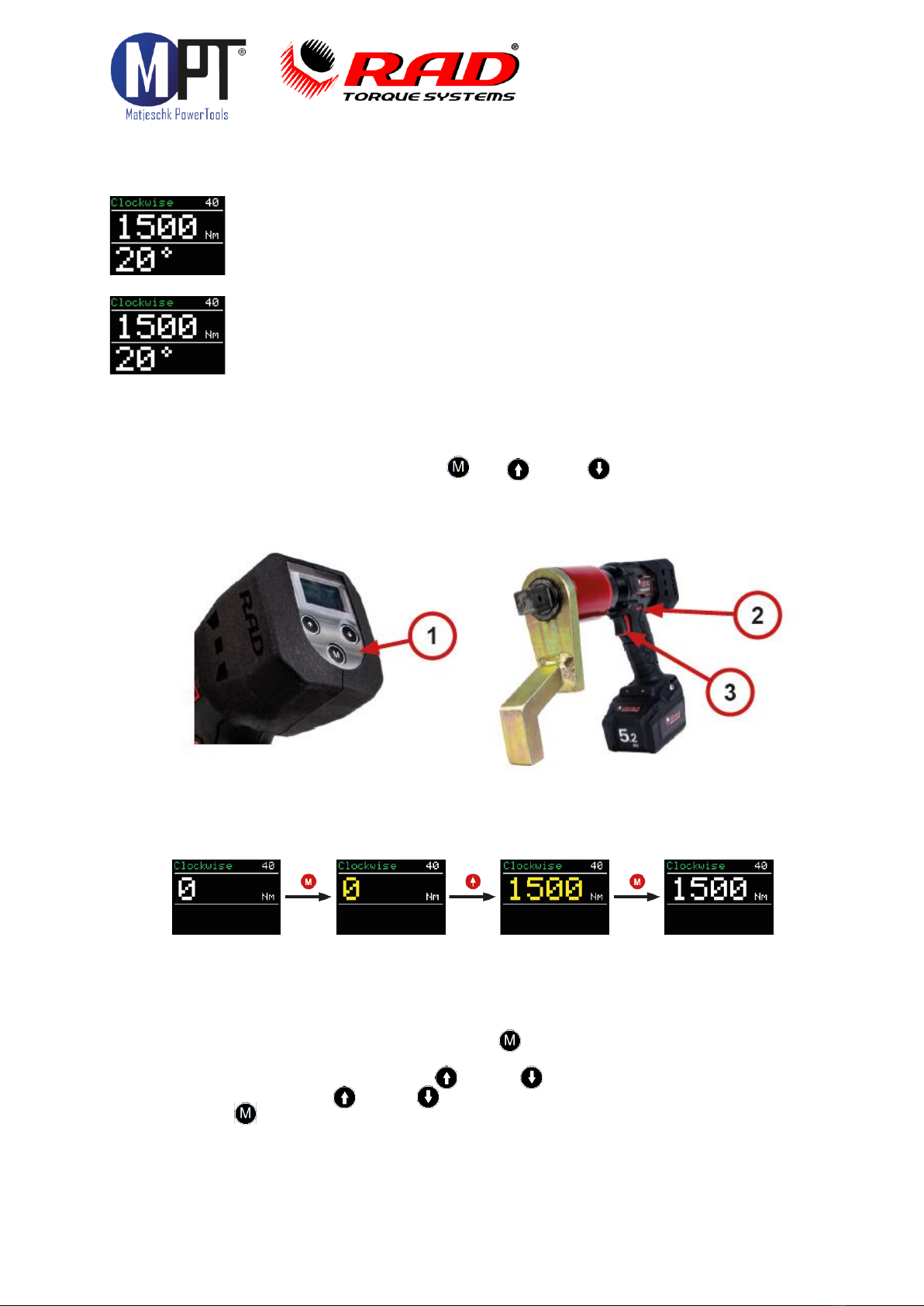
5.2. Preparing the torque wrench
1. Attach the reaction arm (2) to the gearbox of the torque wrench (1).
2. Secure the reaction arm with the retaining ring (3) onto the torque wrench.
3. Attach the socket (4) onto the square of the torque wrench. Use only sockets
with a standardized square in accordance with DIN 3121.
4. Secure the socket with a pin (5).
5. Secure the pin with a snap ring (6) to prevent it from falling out.
5.3. Switching the torque wrench on
When the torque wrench is started, the current time and currently opened
file are displayed. Confirm the screen by pressing the M button. This
screen is displayed only when data logging is active.
MB-RAD
Seite 5
5.4. Indicators on the main screen
•Top left: shows the current direction of rotation
•Top right: torque wrench type (‘40’means MB-RAD 40)
•When the transducer is activated, a blue S is displayed next to the
torque wrench type (B-RAD S series only).
•Centre row: set current torque
•Bottom row: set current angle
•The last result is displayed for 10 seconds
•If an error occurres, the torque on the display turns red. The error can
be acknowledged with any button.
•If the main screen of the torque wrench is active and no buttons are
pressed for 60 seconds, the display switches off
5.5. Operating the torque wrench
•Adjust the settings with the buttons (M), (↑) and (↓) (1).
•The direction of rotation is set with the toggle switch (2).
•Start rotation with the trigger (3).
5.6. Setting the torque
•After being switched on, the torque wrench displays the last set torque.
•The default setting from the factory is 0 Nm.
•The current direction of rotation is displayed at the top left.
•The torque wrench type is displayed at the top right. ‘40’means MB-RAD 40.
•Torque setting is activated by pressing the (M) button briefly.
•The torque indicator now turns yellow.
•The torque is adjusted by pressing (↑)and (↓).
•Pressing and holding (↑)and (↓)adjusts the torque in larger increments.
•Pressing (M) again confi rms the torque.
•The set torque is shown in white.

MB-RAD
Seite 6
5.7. Extended menu
•The extended menu can be opened by using the password. Ask your RAD
distributor for the password.
•The password should be entered under ‘Password’in the main menu.
•The following settings can be implemented in the extended menu:
Advanced settings
•Activate the angle
•Activate the torque limits
•Activate bolt counter
•Deactivating the transducer (B-RAD S series only)
•Point calibration
•Units
•Language
•Unlock (only after consultation your RAD distributor)
•Data logging
Locking the extended menu
5.8. Units
•The torque units can be set in the extended menu.
•The following torque units are possible:
·Newton metres –Nm
·Foot-pound –ft/lbs
·100 setting levels (finer graduations are possible on request)
•Recalibration does not need to be carried out after switching the units.
•A torque chart is required if working in step mode. A torque chart can be obtained
from your RAD distributor.

MB-RAD
Seite 7
5.9. Setting the angle
•To set an angle, the angle option must be activated in advanced settings.
•Setting the angle opens the main screen.
•Torque setting is activated by pressing the (M) button.
•Set the torque.
•Angle can be set after confirming the torque with (M).
•Angle is set by pressing (↑)and (↓).
•Pressing (M) again confirms the angle.
•Angle value can only be set between 10° and 360°.
Please note!
Set torque + angle should not exceed the maximum torque capacity of the tool.
If this threatens to occur, the tool will automatically stop to prevent damage.
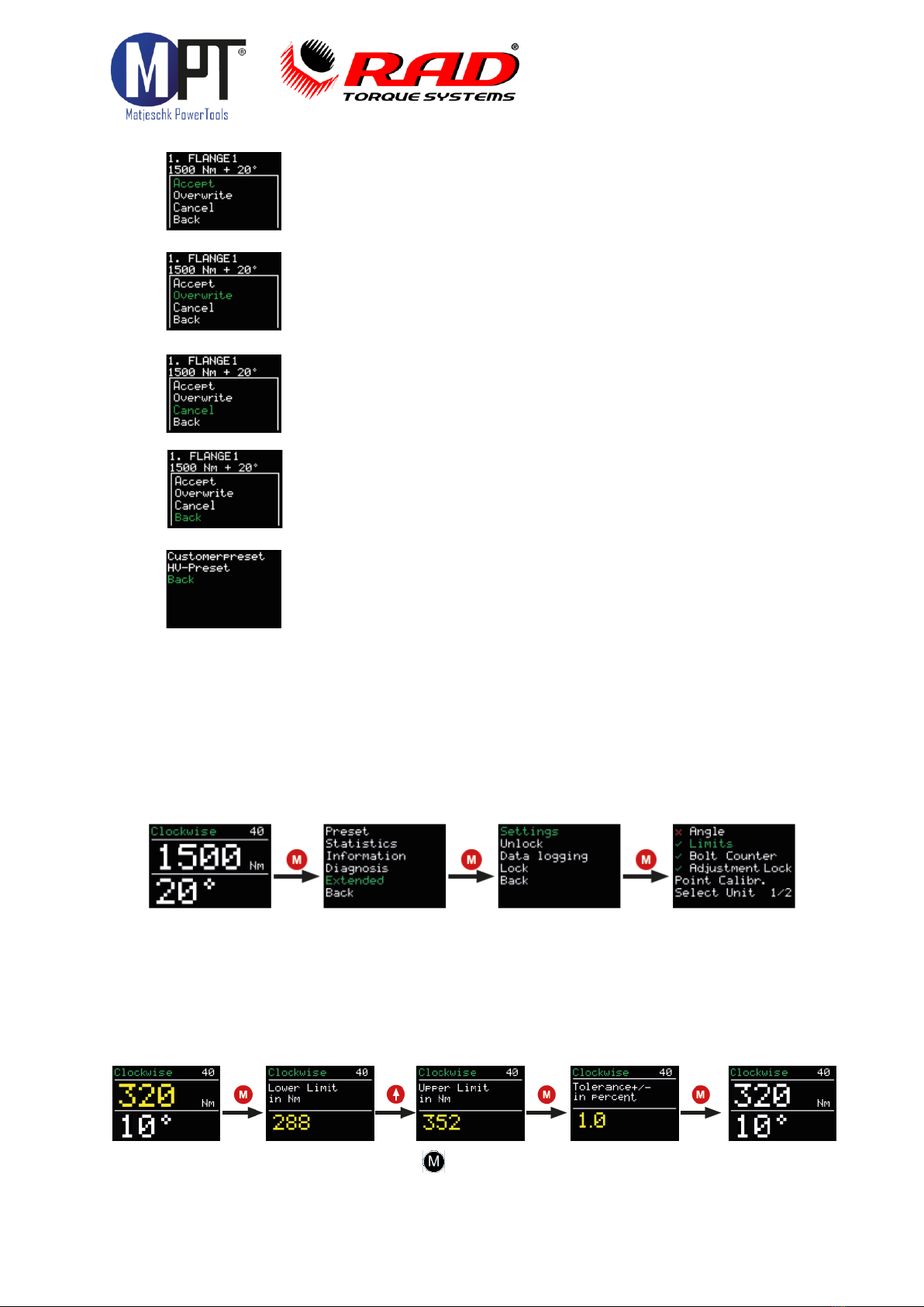
5.10. Presets
•The device can store up to 10 user-defined presets.
•In addition, presets are also stored for standardized HV connections.
•Pressing and holding the (M) button opens the main menu.
•Pressing the (M) button again opens the presets menu.
•Here, you can switch between user-defined customer presets and the HV presets.
•The following is displayed in the preset:
·Reference number of the preset
·Name of the preset
·Torque
·Set angle
·Set limits for the final torque
·Set bolt counter
·Selected program (normal or torque check program)
•The presets can be selected with the arrow buttons ( (↑)and (↓)).
•Pressing the (M) button opens a menu with the following functions:
MB-RAD
Seite 8
•‘Accept’ applies the displayed preset as the current setting.
•‘Overwrite’ will store the preset settings in the current preset.
•To save a preset, first enter the desired torque (+ angle) in the
main screen.
•‘Cancel’ returns you to the displayed preset.
•‘Back’ returns you to the presets menu.
•'Back’ returns to the presets menu of the main menu.
•HV preset can only be selected and cannot be overwritten.
•HV preset are displayed only in accordance with the torque range of the torque
wrench.
•The preset tightening torques for HV bolts refer to the modified torque procedure in
accordance with DIN EN 19963-1-8 for k-class K1.
5.11. Limit settings
•Limits are activated and deactivated in advanced settings:
•Limits can be defined for every final torque.
•Angle limits can be defined for purely torque-controlled tightening. The angle
is counted when the torque wrench’s minimum torque is reached and will only be
measured after the tool has reached its minimum torque.
•Limits can be defined for the final tightening torque for torque/angle tightening.
•The limits are entered on the main screen after the torque and angle have been set:

MB-RAD
Seite 9
•The limits are confirmed with the (M) button.
•The limits are also stored when storing as a preset.
•In the event that the limits are not met or are exceeded when operating, an
indicator appears on the screen.
•The torque wrench can be operated again after pressing any button.
5.12. Bolt counter
•The bolt counter is activated and deactivated in advanced settings:
•The bolt counter is set on the main screen:
•Once activated, the bolt counter must be set to a minimum of 1 and can be set
to a maximum of 999.
•The bolt counter counts all completed bolting operations in a clockwise direction.
Counter clockwise will be ignored.
•Once all bolts have been tightened, the device is locked. The device can be released
in two ways:
·Resetting the number of individual bolts.
·Deactivating the bolt counter.
•If the battery is removed from the torque wrench before the bolt counter is
complete, the counter will resume from the same point the next time the torque
wrench is used.
•To prevent the individual bolts from being torqued twice, e.g. by tightening a bolt
that has already been tightened (“rehit”), the counter should be used in combination
with the limit setting. For instance a minimum Angle must be achieved to count as a
correct tightening.
MB-RAD
Seite 10
5.13. Adjustment lock
•The adjustment lock is activated and deactivated in advanced settings:
•If the adjustment lock is active, the torque can no longer be adjusted in the basic
acces level.
•Only torques stored in the presets can be selected.
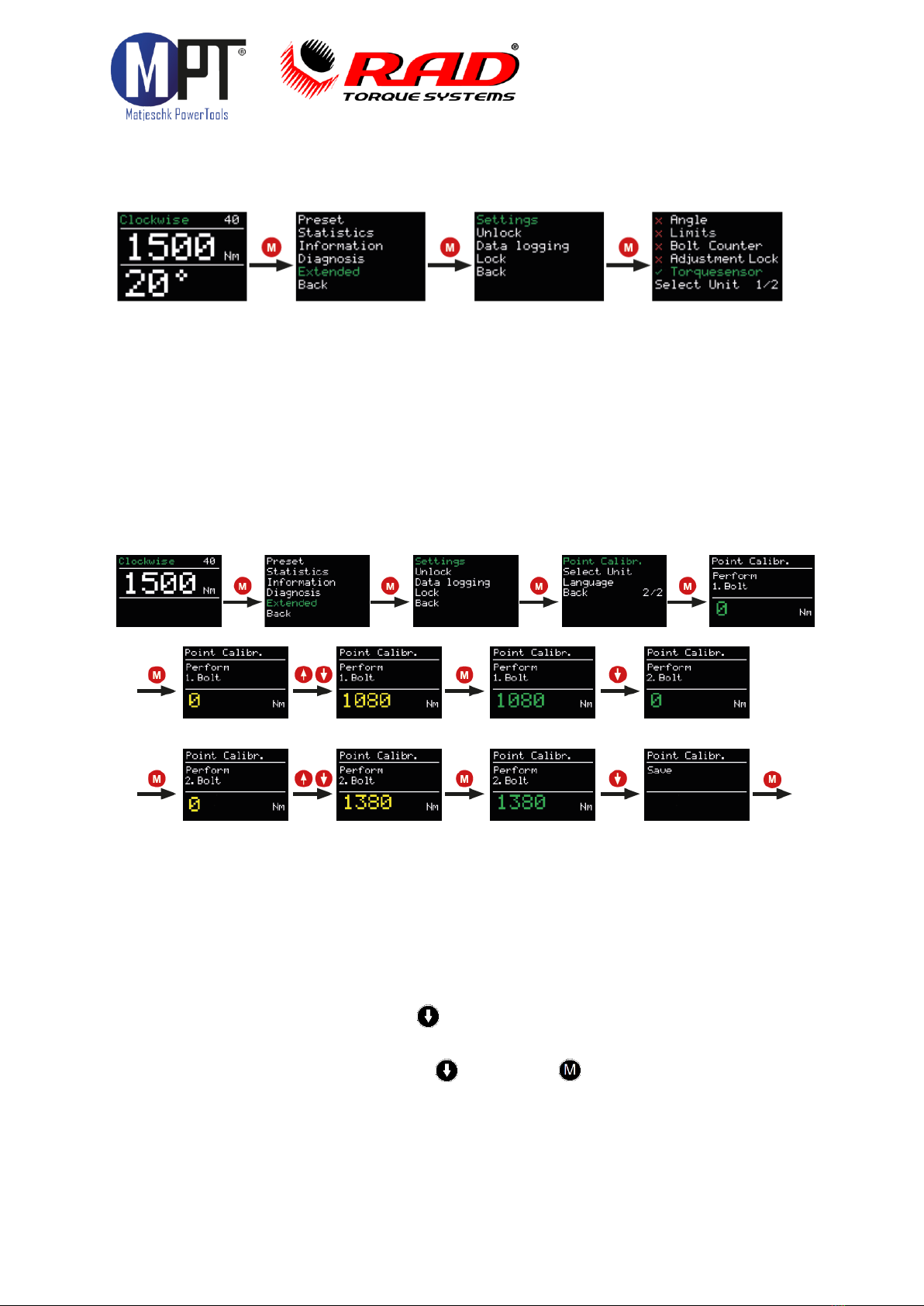
5.14. Point calibration (MB-RAD only)
Point calibration allows the accuracy of the torque wrench to be increased to a specific
type of bolted joint. Since the B-RAD S has a built-in transducer, Point calibration is not
needed for the B-RAD S.
•To verify the actual torque, a measuring instrument such as a
•Smart Socket™ is required.
•The desired torque is set on the main screen.
•The point calibration can be stored in the presets.
•Point calibration is activated under ‘Point calibr.’ in the extended menu.
•‘Perform 1. bolt’ appears on the display.
•The first bolting operation is then carried out.
•The result obtained from a measurement is showed on the display.
•The second bolt is selected with .
•The second bolting operation is then carried out.
•The result is entered on the display.
•Point calibration is completed with followed by .
MB-RAD
Seite 11
5.15. Language
•Five different languages can be selected in advanced settings:
·German
·English
·Spanish
·French
·Dutch
•The torque wrench restarts after confirming the language.
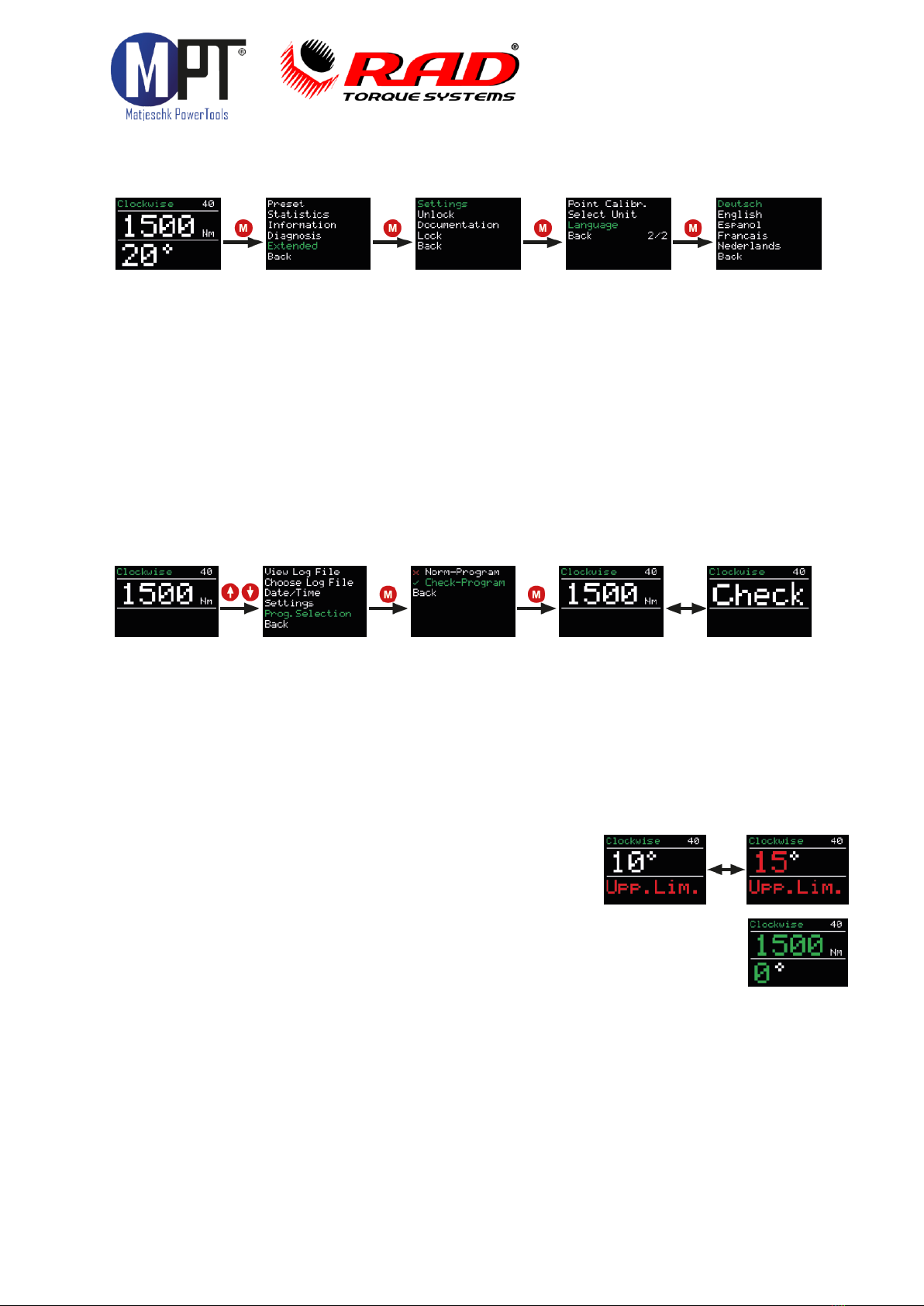
5.16. Check program / Bolt verification
•The ‘Check’ program is NOT an standard feature on the MB-RAD, but can optionally
be equipped or retrofitted with it.
•It has been designed for checking already tightened bolts.
•The Check program can be set via the program selection option:
•With the check program set, the display alternates between the word Check and the
set torque.
•The Check program establishes the selected torque slowly.
•If the actual torque on the bolt is lower than the check torque, the torque wrench
tightens the bolt to the set torque.
•After completing the operation, the Angle of this movement is displayed. If limits
have been activated in advanced settings, the torque wrench evaluates the
“controlled Angle”.
•If the controlled angle is outside of the set limits,
the display turns red. The abbreviation
‘Upp. Lim.’ or ‘Low. Lim.’ appears.
•The error can be acknowledged by pressing any button.
•If the controlled angle is within the set limits, the display
turns green and the controlled angle is displayed.
•The torque wrench rotates slower in the Check program than in
the normal program.
•Due to the elasticity of the reaction arm, a controlled angle of approx.
1 - 3° is displayed even for non-moving bolted joints. This must be determined at the
beginning of the test and taken into account in the evaluation.

MB-RAD
Seite 12
5.17. Data logging
•Data logging is a standard feature on the MB-RAD & B-RAD S.
•When the data logging is active, the sub-item ‘data logging’ appears in the extended
menu.
•ressing the two arrow buttons simultaneously is a shortcut to enter
the data logging menu.
•The data logging menu contains the following sub-items:
·View log file: view the data for all completed bolts.
·Select log file: create a new log file.
·Date/time: set the current time.
·Settings: activate and deactivate the operator ID and data transfer to a PC.
·Program selection: switch between the normal program and the check program.
•The following data are saved to the log files:
·Sequential number: a sequential number is assigned to each tightening
where a torque is applied that exceeds the minimum torque of the tool.
·Operation number: an operation number is assigned to every
bolt successfully tightened in a clockwise direction.
·Date and time of the bolting operation
·Set and final torque
·Set torque unit
·Set and final angle
·Final torque with angle tightening
·Set limits
·Total angle and bolting time
·Battery voltage
·Program use (normal/prove)
·Operator
•A new log file can be created under ‘Select log file’.
•This is activated with ‘Save’.
•Pressing and holding the M button deletes the entry.
•When a blank entry is saved, the device automatically continues to use the last file.

MB-RAD
Seite 13
5.18. Setting the data and time
•The data and time are only displayed and used if data logging is active.
•The date and time can only be set if the extended menu has been unlocked
with the password.
•The time can be synchronized with the supplied software.
5.19. Operator ID
•The operator ID is activated and deactivated in the data logging settings.
•If the option has been activated, the torque wrench asks for an 8-digit operator
designation when the toolkit is switched on. This is recorded in the data logging.
5.20. Total counter and maintenance counter
•The total counter and maintenance counters can be found under ‘Statistics’ in the
menu.
•The maintenance counter indicates the number of bolts tightened since the last
maintenance was carried out.
•The total counter indicates the number of bolts tightened overall.
•The counters are divided into:
·0 - 20% of the maximum torque
·21 - 80% of the maximum torque
·81 - 100% of the maximum torque
·0 - 100% of the maximum torque (‘Total’)
•When more than 20.000 bolts have been tightened, ‘Schedule maintenance’
appears on the display when the device is switched on.
MB-RAD
Seite 14
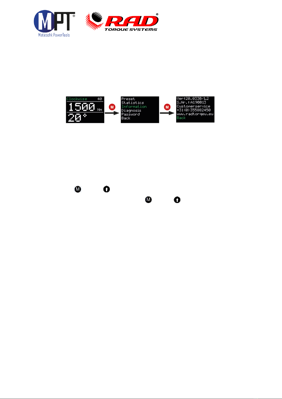
5.21. Toolkit information
•The following information is displayed under „Information“ in the menu:
·The software version number
·The torque wrench serial number
·The customer service telephone number
·The manufacturer´s website
5.22. Diagnosis function
•Torque wrench data can be found under ‘Diagnosis’ in the menu.
•The ‘Status’ entry indicates the progress through the cycle until the next
maintenance is due. The torque wrench should undergo maintenance when this
reaches 100%.
•This menu is intended solely for remote maintenance by telephone.
5.23. Button lock
•Press the (M) and (↑)buttons together for 3 seconds to activate the
button lock.
•To deactivate the button lock, press the (M) and (↑)buttons together for
3 seconds.
•When the button lock is active, the display can no longer be operated.
•The torque wrench continues to operate as set when the button lock is active.
5.24. Temperature monitoring
Temperature monitoring prevents the torque wrench from heating up excessively. A
warning is displayed beyond a motor temperature of 120°C.

MB-RAD
Seite 15
6. Datalogger PC software
6.1. Adding the torque wrench with Bluetooth in Windows
•Install the Bluetooth stick (supplied).
•Activate the data connection on your torque wrench. To do this, go to →Extended
→Data logging →Settings →Data transfer in the torque wrench’s menu.
•Select ‘Devices and printers’ in the PC’s configuration menu.
•Select ‘Add device’.
•Select the torque wrench’s serial number (e.g. M123456).
•Click on ‘Next’.
•When the torque wrench has been successfully added, click on ‘Close’.
•In the ‘Devices and printers’ window, click on the torque wrench’s serial number
with the right-hand button.
•Select ‘Properties’.
•Select the ‘Hardware’ tab.
•Select standard serial connection from Bluetooth.
•Select properties and you will find the corresponding COM port in the name
designation of the Bluetooth connection (e.g. ‘COM11’).
•Close all windows.
6.2. Installing the software in Windows
•Install the software by starting the file ‘setup.exe’.
•Confirm the terms of the licence by click on ‘I agree’.
•Click on ‘Next’.
•Select an installation location and click on ‘Next’.
•Click on ‘Next’.
•When the installation is complete, click on ‘Close’.
•End data connection on your torque wrench by clicking on ‘Back’.
6.3. Configuring the software
•Open the ‘Datalogger’ software by clicking on the link on your desktop.
•Under ‘Select port’, select the COM port that you identified in 4.1.10 (e.g ‘COM11’).
6.4. Download data from torque wrench
•Activate the data connection on your torque wrench. To do this, go to →Extended
→Data logging →Settings →Data transfer in the torque wrench’s menu.
•Click on ‘Load data’.
•If selecting the torque wrench for the first time, name the torque wrench with the
serial number of the torque wrench.
•Confirm with ‘Save’.
•If loading a new file, enter a name (optional).
•Confirm with ‘Save’.
•The progress of the download is shown at the bottom left of the screen. Around 3
data sets are downloaded per second.
•Once the download is complete, the torque wrench and the file can be selected at
the top left.
•The name of the torque wrench and the file, as well as a data table, appear on the
screen.

MB-RAD
Seite 16
6.5. Saving and printing the data
•To print to a printer, select ‘Print’ on the ‘Menu’ tab.
•To save as a PDF, select a PDF printer in the print menu.
•To save as a .csv or .xlsx file, select ‘Export’ on the ‘Menu’ tab, followed by the
corresponding file ending.
6.6. Synchronizing the time
•Activate the data connection on your torque wrench.
To do this, go to →Extended →Data logging →Settings →Data transfer in the
torque wrench’s menu.
•Select ‘Set RTC’ on the ‘File’ tab.
7. Battery
Warning!
Before initial use, check that the voltage and frequency stated on the charger’s
rating plate match the figures for your own electrical supply.
Warning!
Unplug charger immediately if the cable or charger is damaged. Unplug
immediately if any sign of smoke or flames.
Warning!
To reduce risk of injury, charge only rechargeable RAD batteries, other types of
batteries may burst causing personal injury and damage.
Warning!
Do not submit the casing to impact or drill into the casing. Do not throw battery
packs or charger in fire or immerse in water. Keep battery packs dry. Do not use
any damaged or deformed battery packs.
Warning!
RAD chargers should only be operated between 0-49 degrees Celsius. Keep away
from moisture.
Warning!
Slightly acidic, flammable fluid may leak from defective Li-ion battery packs. If
battery fluid leaks out and comes into contact with your skin, rinse immediately
with plenty of water. If battery fluid leaks and comes into contact with your eyes,
wash them with clean water and seek medical treatment immediately.
Lithium-ion battery chargers are to be used exclusively for charging RAD 18V Lithium-ion battery
packs with the maximum capacity of 5.2 Ah or 8.0 Ah.
Note:
To prevent the battery from draining, always remove battery from tool before storage.
7.1. Battery pack faults
Warning indicator stays on
The battery pack is not being charged. The temperature is too high or too low. If the temperature
of the battery pack is between 0 - 49 degrees Celsius, the charging process begins automatically.
Warning indicator flashes on
The battery pack is defective, remove from charger immediately.
The battery fails to charge, contacts may be dirty. Remove the battery pack, clean the contacts
and replace the charger.

MB-RAD
Seite 17
Note: In the case of prolongued activity of electromagnetic disturbances, the battery
charger ends the charging process prematurely for safety reasons. Remove the plug and
plug in again after 2 seconds.
Warning beep
In the case of overheating, the battery will give a loud beep tone. The Lithium-ion battery should
be disconnected immediately to cool down. The Lithium-ion battery can be used again once it is
cooled down.
8. Battery charger
Before initial use, check that the voltage and frequency stated on the rating plate match
your own electrical supply and check that the ventilation slits are clear. Minimum clearance
from other objects is 5 centimeters.
1. Connect to electrical supply, the red and green indicator lights up for approximately
1 second.
2. Once the self test is completed, the indicator lights are off.
3. Insert the battery pack into the charging shaft socket; push it to the back until it
engages.
4. Charge the battery pack before use. Only once it has been charged and discharged five
charging cycles does the battery pack reach its full charging capacity. You may store
charged Lithium-ion battery packs and recharge them after an interval of no more than
six months.
8.1. Removing and inserting the battery pack
Removal: Press and hold the release button and remove the battery pack.
Inserting: Slide in the battery pack until it engages.
9. Movement of the reaction arm
Diese Bedienungsanleitung wurde mit größter Sorgfalt erstellt. Sollten Ihnen dennoch
Auslassungen oder Ungenauigkeiten auffallen, so teilen Sie uns diese bitte auf angegebener
Adresse mit.
M-PT übernimmt keinerlei Haftung für technische und typographische Fehler und behält
sich das Recht vor, jederzeit ohne vorherige Ankündigung Änderungen am Produkt und an
den Bedienungsanleitungen vorzunehmen.
M-PT ist nicht für direkte und indirekte Folgeschäden haftbar oder verantwortlich, die in
Verbindung mit der Ausstattung, der Leistung und dem Einsatz dieses Produkts entstehen.
Es wird keinerlei Garantie für den Inhalt dieses Dokuments übernommen.
Bei Schäden die durch Nichtbeachten dieser Bedienungsanleitung verursacht werden,
erlischt der Garantieanspruch. Für Folgeschäden übernimmt M-PT keine Haftung!
9.1. Installing the reaction arm
Ensure the reaction arm and retaining ring are installed securely to hold the reaction arm in
place. Make sure the reaction arm is in contact with a solid reaction point before you operate the
tool. When the tool is in operation the reaction arm rotates in the opposite direction to the
output square drive and must be allowed to rest squarely against a solid object or surface
adjacent to the bolt to be tightened, see Figure 6.

MB-RAD
Seite 18
WARNING: While in use, this tool must be supported at all times in order to prevent
unexpected release in the event of a fastener or component failure!
9.2. Reaction arm height
Ensure the height of the socket is even with the height of the reaction arm as seen below in
Figure 6A. The height of the socket cannot be shorter or higher than the height of the reaction
arm as seen below in Figure 6B and Figure 6C.
NOTE: Improper reaction will void warranty and can cause premature tool failure.

MB-RAD
Seite 19
9.3. Reaction arm foot
Ensure the foot of the reaction arm aligns with the length of the nut as seen in Figure 7A.
The length of the foot cannot be shorter or longer than the nut as seen in Figure 7B and
Figure 7C.
9.4. Reaction point
Ensure the reaction arm reacts off the middle of the foot as seen in Figure 8A. Do not react
off the heel of the reaction foot as seen in Figure 8B.
Please contact RAD Torque Systems B.V. or your local RAD authorized distributor for
custom reaction arms.
WARNING: Always keep your hand and body parts clear of the reaction arm and
barrel when the tool is in operation, see Figure 8C.
Note: FOR ADDED SAFETY, WE ADVISE TO ORDER THE OPTIONAL THE DOUBLE
SAFETY TRIGGER WITH PART NO: 25949. THIS REDUCES FINGER PINCHING
HAZARDS.

MB-RAD
Seite 20
10. Safety
RAD tools are developed for tightening and loosening threaded fasteners using very high
forces. For your safety and that of others, warning labels and attention labels are
prominently attached to the torque wrench and its accessories.
NOTE: Make sure you observe the directions on the warning labels at all times.
RAD tools have been designed with safety in mind however, as with all tools you must
observe all general workshop safety practices, and specifically the following:
•Before using your new tool, get familiar with all its accessories and how they work
•Always wear safety goggles when the tool is in operation
•Make sure the reaction arm is in contact with a solid contact point before you
operate the tool
•Keep your body parts clear of the reaction arm and the contact point
•Make sure the reaction arm retaining ring is securely in place to hold the reaction
arm or blank in place.
RAD tools are safe and reliable. Not following precautions and instructions outlined here
can result in injury to you and your fellow workers. RAD Torque Systems B.V. is not
responsible for any such injury.
11. Warranty
11.1. New tool warranty
Any new tool branded with the RAD name and purchased from RAD Torque Systems B.V., or
through one of its authorized distributors or agents, is warranted to the original purchaser
against defects in materials and workmanship for a period of twelve (12) month from the date of
delivery to the end user. This guarantee is valid until fifteen (15) months after the original
calibration date.
Furthermore, the warranty conditions determine that no warranty applies if:
1. The defect, wholly or partly, is due to unusual, inappropriate, improper or careless use of the
product;
2. The defect, wholly or partly, is due to normal wear and tear or lack of proper maintenance;
3. The defect, wholly or partly, is due to installation, assembly, modification and / or repair by the
customer or by third parties;
4. The product is altered, modified, used or processed;
5. The product is transferred to a third party;
6. RAD Torque Systems B.V. has obtained the product, wholly or partly, from a third party, and
RAD Torque Systems B.V. can not claim compensation under warranty;
7. RAD Torque Systems B.V. in manufacturing of the product raw materials, and suchlike has
used those on the instructions of the customer;
8. The product has a small deviation in it’s quality, finishing, size, composition and suchlike,
which is not unusual in the industry or if the defect was technically unavoidable;
9. The customer has not fulfilled all obligations under the agreement promptly and correctly
towards RAD Torque Systems B.V..
This manual suits for next models
1
Table of contents
Other M-PT Power Tools manuals


