JessEm Tool Mast-R-Fence Service manual

Operating
Instructions and Parts Manual
Mast
-
R
-
Fence and Rout
Models:
JessEm Tool Company
61 Forest Plain Road
Oro-Medonte, Ontario, Canada
L3V 0R4
Local: 705-726-8233
Fax: 705-327-0295
Toll Free: 1-866-272-7492 Website:
www.jessem.com Email:
Instructions and Parts Manual
Fence and Rout
-
R
-
Fence
Models:
04010 and 04100
Fence

Thank you for choosing this product from JessEm Tool Company. We appreciate your
support and hope thatour product serves you well. This product is designed to provide
many years of reliable service provided it is used as intended and taken care of.
This user manual will assist you in assembly and general operation of this product. It
is not our intent to teach you about woodworking. It is assumed that you are an
experienced woodworker with the basicskills and experience necessary to usethis
product safely. If after reading the following instructions, if you are unsure or
uncomfortable about safely using this product we urge you to seek additional
information through widely available woodworking books or classes.
As part of our Continuous Product Improvement Policy, JessEm products are
always advancing in design and function. Thereforethere may be differencesbetween
what is shown in our catalogs, website or at retail display and what is sold at time of
purchase. We reserve the right to make positive changes to our products at our
discretion.
JessEm Tool Company Warranty
All JessEm products are warranted tobe free from defects in material and
workmanship. JessEm will repairorreplaceanyproductwhich upon inspection proves to
be defective for aperiod of (1) yearfrom dated receipt and proof of purchase. All
warranty claims should be made direct to JessEm Tool Company. Contact JessEm
for a warranty claim return authorization and instructions to proceed. The consumer
is responsible for shipping costs to return product to JessEm Tool Company. We will
repair or replace the product at our discretion and JessEm Tool will return shipment to
you at no charge.
Warranty Limitations
This warranty does not cover:
Repairsor alterations madeor attempted byanyoneotherthanJessEmTool
Companyoranauthorized JessEm service professional.
Normal wear and tear
Abuse, misuse or neglect.
Improper careor maintenance.
Continued use after partial failure.
Products that have been modified in any way.
Products used with improper accessories.
Prematurethread-wearduetoadjusting height with electric or cordless drill.

Important Safety Precautions
Before operating any machinery or power tool,read andunderstand all safety
instructions in the owner’s manual for the tool or machine.
If you donot haveamanual,contact the manufacturer and obtain one before
using any tool or machine.
Always wear eye protection in compliance with ANSI safety standardswhen
operatinganypowertools or machinery.
Always use proper guards and safety devices when operating power tools and
machinery.
Carefully checkrouter bits before each use. Do not useif damageor defect is
suspected.
Donot exceedtherecommendedRPM for any router bit.
Do not wear loose clothing or jewelrythatmaycatch ontools, machineryor
equipment.
Unplug the tool or machine when mountingor makingany adjustmentsto
mechanical performance.
Routing Safety Precautions
Alwaysmakesurethefenceonyourrouter table is locked firmly into
position before each use.
Never force the bit or overload the routerbeyondthe expectations of thetool.
Be surethat atleast 3/4 oftheshank length is inserted securely in the router
collet.
Never bottom outthebit inthecollet. Allow 1/8” clearance between bottom of
sank and bottom of collet.
Always rout in two or more passes when large amounts of stock must be
removed.
Use reduced RPM speeds for larger diameter router bits.
Suggested Router Bit Speeds
Bit Diameter Max. Speed
1” (25mm) 24,000 RPM
1-1/4”-2”(30-50mm) 18,000 RPM
2-1/4” - 2-1/2” (55-65mm) 16,000 RPM
3”-3-1/2”(75-90mm) 12,000 RPM
CALIFORNIA PROPOSITION 65
WARNING
This product contains lead known to the State
of California to cause cancer or reproductive
harm. Components made of brass are known
to contain lead. Wash hands after using this
product.

Tools Required for Assembly
Phillips screw driver
10 mm wrench or socket
3/16” Drill Bit*
1/16” Drill Bit*
*Note: This is required if you are not mounting to a Je
Assembling
the Fence Tracks
There are two different types of fence
tracks depending upon which model
fence you have purchased.
Fence model 04010 (Master Fence)
has a table mounting bracket provided
with a T-
nut slot for mounting
fence to the bracket (Fig 1)
. When
assembling the table mounting bracket
to the fence track use a 6mm hex bolt
with a flat washer and insert the bolt
into the lower slots on the fence track.
Screw the T-
nuts onto the bolts. Slide
the T-nuts into the T-
slot on the table
mounting bracket. Do not tighten this
assembly at this stage.
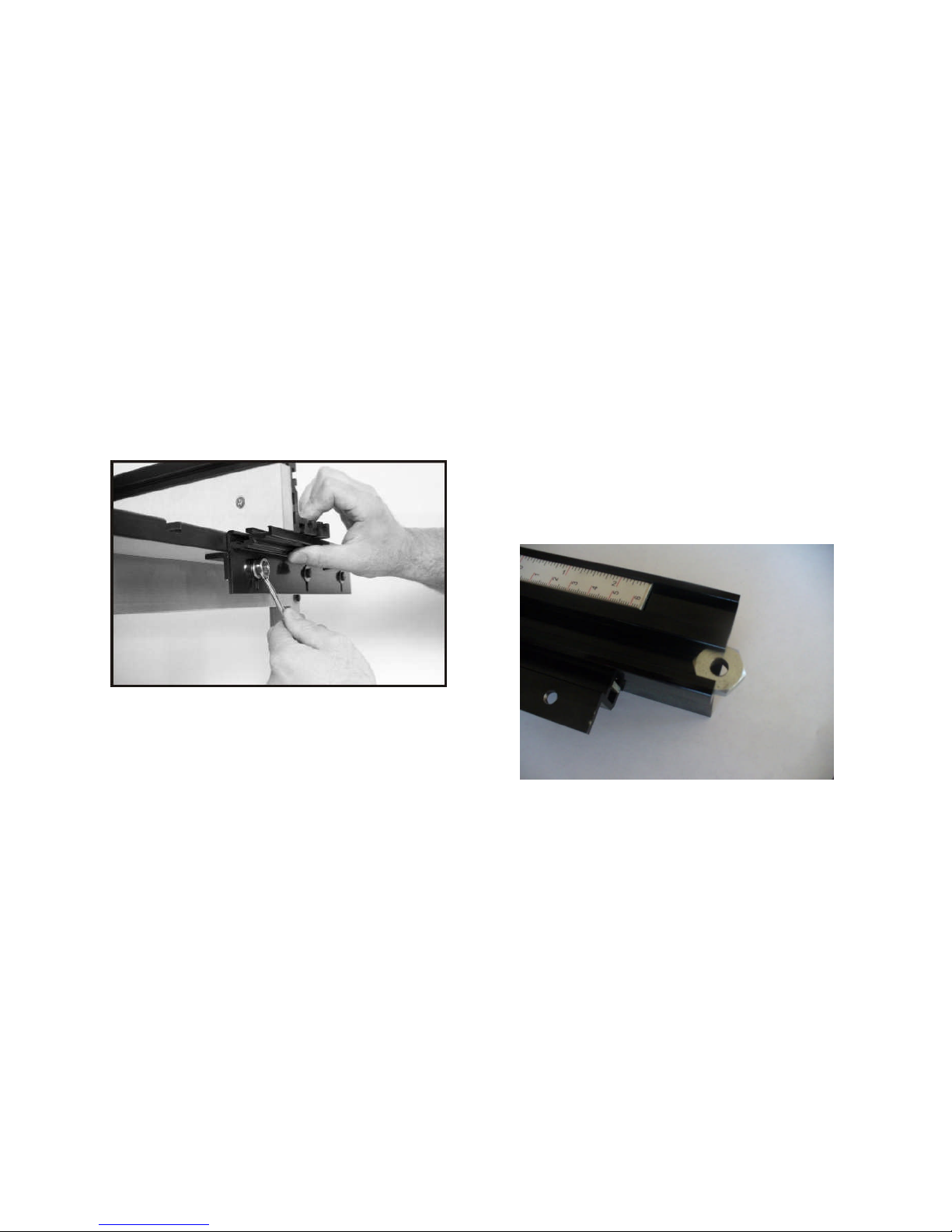
Fence model 04100 (Router Fence)
has a table mounting bracket but does
not have the T-
slot in the bracket as
Model 04010.
Mount the table bracket
directly to the fence track using 6mm
hex bolts
and flat washers (Fig. 2)
not tighten this assembly at this stage.
Tools Required for Assembly
10 mm wrench or socket
*Note: This is required if you are not mounting to a Je
ssEm table top.
the Fence Tracks
There are two different types of fence
tracks depending upon which model
fence you have purchased.
Fence model 04010 (Master Fence)
has a table mounting bracket provided
nut slot for mounting
the
. When
assembling the table mounting bracket
to the fence track use a 6mm hex bolt
with a flat washer and insert the bolt
into the lower slots on the fence track.
nuts onto the bolts. Slide
slot on the table
mounting bracket. Do not tighten this
Fence model 04100 (Router Fence)
has a table mounting bracket but does
slot in the bracket as
Mount the table bracket
directly to the fence track using 6mm
and flat washers (Fig. 2)
. Do
not tighten this assembly at this stage.
Figure 1
Figure 2

Figure 3
Figure 5
Note: If you are mounting the fence to a
JessEm table top proceed to the next
page section “For JessEm table”.
Measure the distance from the front edge of your
table to the center of the bit hole in the table top.
Transfer a mark the same distanced on both the
left and right edges of the table top. Then drawa
center line across
the top of the table from one
Take one of the fence track assemblies and
line it up with the mark you made in figure 4.
Make a mark on the underside of the table
top to locate the same position on the bottom
of the table (Fig. 5).
Mounting the Fence Tracks to the Table
Figure 4
Figure 6
From the center line you drew, come three
inchestoward thefront ofthe tableand mark a
small line on both the left and right sides of
the table (Fig. 4).
Flip the table top over and position the fence
bracket upside down and line up the frontedge
withthemarkyou made instep5.Using a
pencil or a 3/16” diameter drill bit mark the 4
holes for mounting the fence bracket. Pre-drill
the holes using a 1/16” diameter drill bit and
be sure you don’t drill through the table top
surface (Fig. 6). Using the #6 x ¾” wood
screws secure the fence track assembly to the
table. Repeat all steps for the second fence
bracket.
For JessEm Table Top
Leveling the Fence Track
If you are mounting the fence to aJessEm
table top the top is already pre- drilled for
the fence mounting angle brackets. With
the table upside down position the left and
right fence track assemblies andattach to
the table with the 6mm x45mmsocket head
cap screws for phenolic tablesand 4.8mm x
25mm wood screws forMDFtables and
proceed to the next step.
Figure 7
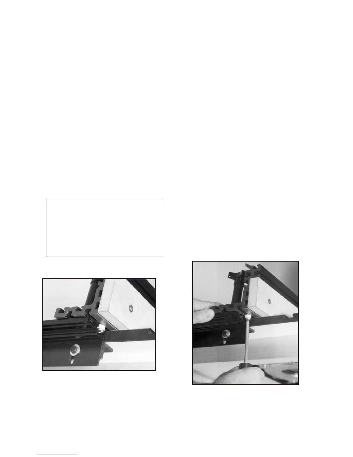
Move the fence back and use it to position the
rear end of the bracket in the same way and
tighten the rear bolt. Then tighten the center bolt
to complete the leveling of the fence track.
Repeat this process for the fence track on the
other side of the table.
When tightening the fence track mounting bolt on
Model 04010, the T-nut will tighten in the T-track
and hold the fence track securely. When
tightening the fence track mounting bolt on Model
04100 you will need a 10mm wrench to hold the
hex nut while tightening the hex bolt securely.
Mounting the Fence to the Tracks
Figure 8
Place the fence on the table top in its upright
position and allowittohang overthetable
edgeandlieacrossthefront endofthefence
track. Raise the fence track assembly sothat
it is positioned flush to the bottom of the fence
as it rests on the table top. With a 10mm
wrench or socket tighten the front bolt of the
fence assembly (Fig. 7).
Slide the ¾” hex T-nut for the extension
knob into the T- slot next to the scales on
the fence track (Fig. 8). The extension
knobs will thread into these nuts to hold the
fence in position. To do so, position the end
of the fence over the track and look directly
down through the open slot in the base of
the fence frame and visually line up the hole
in the rectangular T-nut.

Then insert the threaded tip of the
extension knob through theslot fence and
into the threaded hole inthe T- nut (Fig. 9).
Twisting the lock-down knob clockwise will
fasten the fence to the tracks andhold the
fence firmly in position.
Figure 9
The scales on the fence tracks are
adjustableforaddedversatility in
positioningthe fence. Toadjust the
scales loosen the knurled nut
underneath the fence track adjust the
scale and re-tighten the nut (Fig. 10).
You can use the scales as a zero
referencepoint byadjusting thescales to
“0”once your fence is set up in your
desiredposition relevant to the router
bit you are using. Please note that
fence scales are only available on
Model 04010. Fence scales are not
available for Model 04100.
Figure 10
Adjusting the Fence Track Scales
Figure 11
TheMast-R-Fenceoffersauniquemeans
of keeping the fence centered on the
table with a nylon bushing. Take the
6mm x 15mm bolt and insert into the
1/2”nylonspacerandthreadononeof the
square 6mm nuts. Do not thread the
square nut on all the way. Slide the
squarenut into the front T-slot under the
left end of the fence (Fig. 11). Leave
theassembly loose andapproximately 1”
in from the end of the fence.
Figure 12
Slide the fence with the nylon spacer
attached into the T-slot on the left
fence track (Fig. 12). Thenylon
spacershould be slightly loose to
allow for some movement.
Nowslide thefenceback andcenter the
fence left to right with the center of the
bit opening. Make sure it is parallel
with the front edge of the table or miter
track.
Note: Fence Model 04100 does not
come with the nylon bushing for
centering. Model 04010 is the only
fence equipped with this feature.
Now slide the fence, keeping it
square (use the scales on the fence
track to ensure you are square) to
thefront of the table, just until the
nylon spacer comes out of the
track. Then tighten the bolt on the
spacer being very careful not to
changeitsposition (Fig. 13).
Centering the Fence to the Table
Figure 13

Installing the Sub-
Fences
Locate the sub-fences in the
packaging. Place the sub-
fence
against the front of the fence
extrusion (Fig. 14). Align the holes in
the sub-
fence with the slots in the
fence
extrusion. Insert the 6mm x
45
mm screws through the hole in the
front of the sub-
fences (Fig. 15).
Place the 6mm washer over the sub
fence bo
lt. Screw the black knob
onto the sub-
fence bolt (Fig. 16).
Repeat these steps for the remaining
two holes. Repeat these for the other
sub-fence.
Slidethefencebacktothecenterofthe
table. Re-
check to see if the fence is
centeredonthe table.Ifnot repeatuntil
you
achieve your desired result.
Figure 14
Fences
fence
extrusion (Fig. 14). Align the holes in
fence with the slots in the
extrusion. Insert the 6mm x
mm screws through the hole in the
fences (Fig. 15).
Place the 6mm washer over the sub
-
lt. Screw the black knob
fence bolt (Fig. 16).
Repeat these steps for the remaining
two holes. Repeat these for the other
Slidethefencebacktothecenterofthe
check to see if the fence is
centeredonthe table.Ifnot repeatuntil
achieve your desired result.
Figure 14
Figure 15
Figure 16
Figure 17

Installing Sub-
Fence Offset Track
Fence Model 04010 and Model 04100 are both
equipped with sub-fence offse
t tracks. These
offset tracks are designed to be installed two
allow for a 1/32” or 1/16” offset of the sub
Notice the
female profile of the extrusion, you will
see that one side of the profile is deeper than the
other side. The small side is 1/32” and the
deeper side is 1/16”.
The sub-
fence offset tracks are located on the
backside of the fence in a specially designed
storage location (Fig. 17).
Remove one side of the fence sub-
fences by
unscrewing the black knob and removing the
sub-fence bolts (Fig. 18)
. Once the sub
has been removed, notice the end of the fence
extrusion. The fence extrusion is designed with
ma
ting male profiles designed to accept the
offset tracks (Fig. 19
). Side the offset tracks
onto the fence extrusion take care that you install
both o
ffsets on the same side (Fig. 20
offsets should always be installed on the same
side to insure the sub-
fence is offset the same
distance at the top and bottom of the sub
Once the offset tracks are securely in place,
reinstall the sub-fence with the sub
-
washer , and black locking knob.
Fence Offset Track
Fence Model 04010 and Model 04100 are both
t tracks. These
offset tracks are designed to be installed two
allow for a 1/32” or 1/16” offset of the sub
-fence.
female profile of the extrusion, you will
see that one side of the profile is deeper than the
other side. The small side is 1/32” and the
fence offset tracks are located on the
backside of the fence in a specially designed
fences by
unscrewing the black knob and removing the
. Once the sub
-fence
has been removed, notice the end of the fence
extrusion. The fence extrusion is designed with
ting male profiles designed to accept the
). Side the offset tracks
onto the fence extrusion take care that you install
ffsets on the same side (Fig. 20
). Both
offsets should always be installed on the same
fence is offset the same
distance at the top and bottom of the sub
-fence.
Once the offset tracks are securely in place,
-
fence bolt,
Figure 18
Figure 19
Figure 20

Attaching the Router Bit Guard
Take the clear polycarbonate guard
and two of the black knurled
knobs
andtwo1/4”squarenuts
. Insert each
knob through each
slot intheguard
andthread a square nut
onto each bolt
end.
Lineupthe nutontheguard assembly
slide each nut into the T-
slot starting from
the end of the fence (Fig. 21). Then
the guard to the center of the fence and
adjust the guard slightly higher than
abovetherouterbit.Besuretheguard
cle
ars the bit. Adjust and tighten securely
before each use and after all bit changes.
Attaching the Router Bit Guard
Take the clear polycarbonate guard
knobs
. Insert each
slot intheguard
onto each bolt
Lineupthe nutontheguard assembly
and
slot starting from
the end of the fence (Fig. 21). Then
slide
the guard to the center of the fence and
adjust the guard slightly higher than
and
abovetherouterbit.Besuretheguard
ars the bit. Adjust and tighten securely
before each use and after all bit changes.
Tools That Make A Difference!
Figure 21
Tools That Make A Difference!

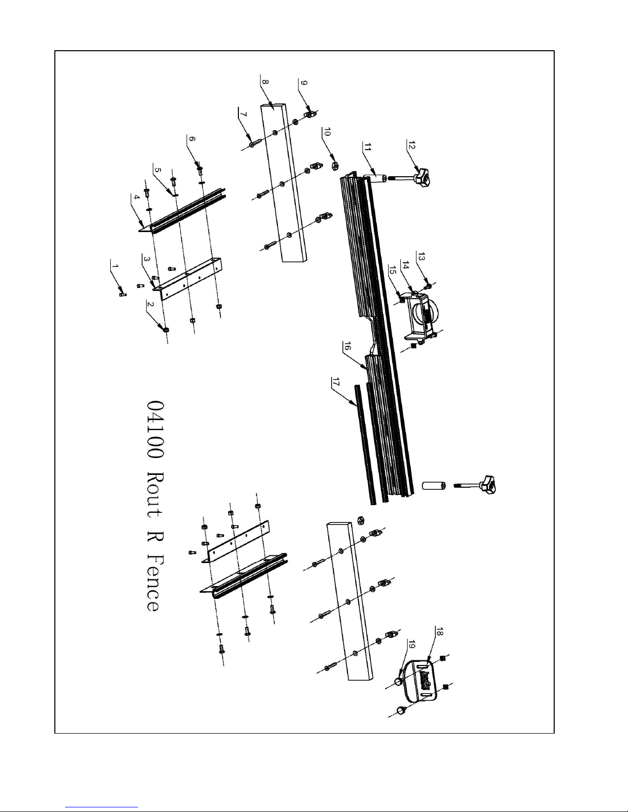
04100 Rout-R-Fence Parts List
Item No. Part No. Description Qty Part Specification
1 04100-001 Fence Track Mtg Angle Wood Screw 8 4.8MX25M
2 04100-002 Fence Track Mtg Nut 6 M6
3 04100-003 Fence Track Mtg Angle 2
4 04100-004 Fence Miter Track 2
5 04100-005 Fence Track Mtg Washer 6 6.5MX14.5MX1.2M
6 04100-006 Fence Track Mtg Bolt 6 M6X16
7 04100-007 Fence Face Mtg Bolt 6 M6X45
8 04100-008 Fence Face 2
9 04100-009 Fence Clamping Knob 2
10 04100-010 Fence Clamping Nut 2 M8
11 04100-011 Knob Extension 2
12 04100-012 Clamping Knob 6
13 04100-013 Vacuum Port Mtg Screw 2 M6X20
14 04100-014 Vacuum Port/Dust Chute 1
15 04100-015 Vacuum Port Square Nut 4 M6
16 04100-016 Fence Extrusion 1
17 04100-017 Fence Shimming Bar 2
18 04100-018 Fence Guard 1
19 04100-019 Fence Guard Locking Knob 2

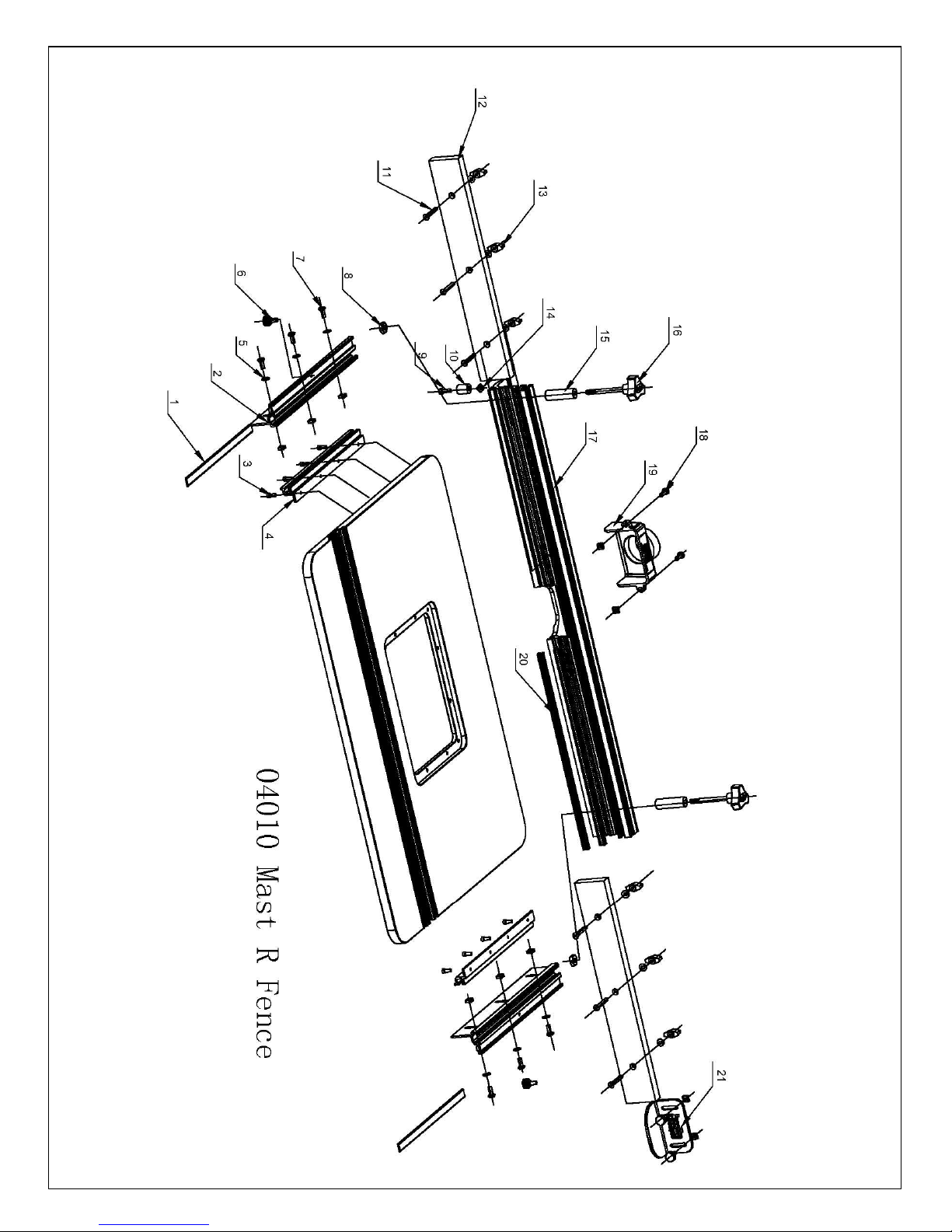
04010 Mast-R-Fence II Parts List
Item No. Part No. Description Qty Specification
1 04010-001 Scale Mounting Bar and Scale 2
2 04010-002 Fence Track 2
3 04010-003 Fence Bracket Mtg Track Screw 8 M5X12
4 04010-004 Track Mounting Angle 2
5 04010-005 Flat Washer 12 6.5X14.5X1.2
6 04010-006 Fence Track Scale Locking Knob 4
7 04010-007 Fence Track Mtg bolt 6 M6X16
8 04100-010 Fence Clamping Nut 2 M8
9 04010-009 Centering bushing bolt 1 M6X15
10 04010-010 1/2" Nylon Spacer 1
11 04100-007 Fence Face Bolt 6 M6X45
12 04010-012 Fence Face 2
13 04100-012 Clamping Knob 6
14 04100-015 Centering bushing nut 11 M6
15 04100-011 Knob Extension 2
16 04100-009 Fence Clamping Knob 2 M8
17 04010-017 Fence Extrusion 1
18 04100-013 Vacuum Port/Dust Chute Screw 2 M6X20
19 04100-014 Vacuum Port/Dust Chute 1
20 04010-020 Fence Shimming Bar 2
21 04100-018 Fence Guard 1
04100-015 Vacuum Port/Dust Chute nut 2
04010-023 Fence Scale 1
This manual suits for next models
1
Table of contents
Other JessEm Tool Power Tools manuals

JessEm Tool
JessEm Tool Mast-R-Lift 02101 User manual

JessEm Tool
JessEm Tool MITE-R-SLIDE II User manual

JessEm Tool
JessEm Tool CLEAR CUT-TS User manual

JessEm Tool
JessEm Tool mast-r-lift II User manual

JessEm Tool
JessEm Tool Mite R Slide User manual

JessEm Tool
JessEm Tool TA FENCE User manual

JessEm Tool
JessEm Tool Rout R Lift PRESTIGE 02322 User manual
Popular Power Tools manuals by other brands


IKH
IKH 6021 instruction manual

Clarke
Clarke Strong-Arm CSA50FPB Operation & maintenance instructions

Opus
Opus Goldpress Plus OPERATING, MAINTENANCE AND SAFE USAGE

Beveler USA
Beveler USA B15 Operation manual

Matatakitoyo Torque Tools
Matatakitoyo Torque Tools MOT2 Operation manual

HART
HART HPIF50 Operator's manual