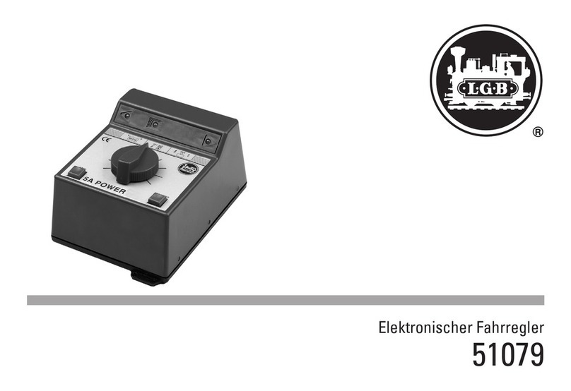
Märklin 55015 User manual

Universalhandy
55015
125963_55015_Universalhandy_A5.indd 1 25.04.2013 13:16:58

2
Inhaltsverzeichnis:
Seite
1. Universal-Handy 3
2. Betrieb mit dem Mehrzugsystem 3
3. Doppeltraktion 4
4. Schalten 5
5. Identifikationsnummer einstellen 5
6.
Reaktionszeit der Pfeiltasten programmieren
6
7. Programmieren der Decoder 6
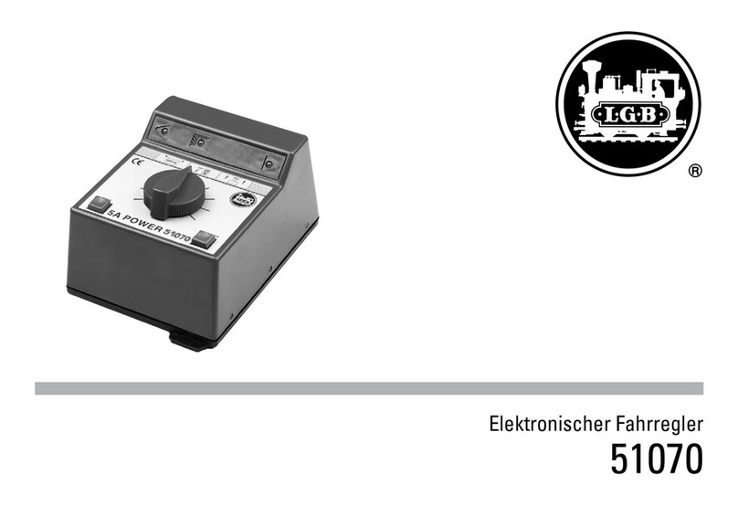
8. Betrieb mit dem Analogfahrregler 51070 7
Table of Contents:
Page
1. Universal Hand Controller 8
2.
Operation with the Multi-Train Control System 8
3. Multiple Unit Locomotive Operation 9
4. Controlling Accessories 10
5. Setting Identification Numbers 10
6. Programming the Reaction Time for the
Arrow Buttons 11
7. Programming Decoders 11
8. Operation with the 51070 Analog
Locomotive Controller 12
Sommaire :
Page
1. Unversal Handy 13
2. Exploitation avec le système multitrain (SMT) 13
3. Double traction 14
4. Commutation 15
5. Définir un numéro d’identification 16
6. Programmer le temps de réaction des
touches de direction 16
7. Programmeation des décodeurs 16
8. Exploitation avec le régulateur
analogique 51070 17
Inhoudsopgave:
Pagina
1. Universele handy 18
2. Bedrijf met het meertreinen-systeem MZS 18
3. Dubbeltractie 19
4. Schakelen 20
5. Identificatienummer instellen 20
6. Reactietijd van de pijltoetsen programmeren 21
7. Programmeren van de decoder 21
8. Bedrijf met de analoge rijregelaar 51070 21
Índice
Página
1. Móvil universal 22
2. Funcionamiento con el sistema multitren 22
3. Doble tracción 23
4. Conmutación 24
5. Configuración del número de identificación 25
6. Programación del tiempo de reacción de las
teclas de flecha 25
7. Programación de los decoders 25
8. Funcionamiento con el regulador de marcha
analógico 51070 26
Elenco del contenuto:
Pagina
1. Comando da palmo universale (Handy) 27
2. Esercizio con il sistema per numerosi treni 27
3. Doppia trazione 28
4. Commutazione 29
5. Impostazione del numero identificativo 30
6. Programmazione del tempo di reazione dei
tasti a freccia 30
7. Programmazione del Decoder 30
8. Esercizio con il regolatore di marcia
analogico 51070 31
125963_55015_Universalhandy_A5.indd 2 25.04.2013 13:16:58

3
1. Universal-Handy
1.1 Funktionen
Folgende Funktionen können Sie vom Universal-
Handy aus steuern:
In Verbindung mit der Mehrzugsteuerung:
• Fahrtrichtung und Geschwindigkeit
• Serielles oder paralleles Auslösen der Zusatz-
funktionen und des Lichts bei entsprechenden
Lokomotiven.
• Programmieren der Lokadressen 00 – 22
• Schalten von MZS-Zubehördecodern (1-128)
• Stellen und Programmieren von bis zu 10 Fahr-
straßen
• Steuern und Programmieren von bis zu 10
Doppeltraktionen
• Programmieren von MZS-Lokdecoder und
MZS-Weichendecoder (55024 und 55025)
• Wahlweise mit LGB 55050/55055 ausbaubar zur
Funkfernsteuerung
In Verbindung mit dem analogen Fahrregler 51070:
• Fahrtrichtung und Geschwindigkeit mit einstell-
barem Regelbereich
!Betriebsbereit nur in Verbindung mit der
LGB-Funkfernsteuerung 55050/55055.
1.2 Anschluss an die Mehrzugsteuerung
An dem Universal-Handy befindet sich ein
Anschlusskabel mit einem viereckigen Western-
stecker am Kabelende. Diesen Westernstecker
schließen Sie an der MZS-Zentrale an die mit
LGB-Bus markierte Buchse.
Das Batteriefach wird nur für den Funk-Betrieb
mit 55050/55055 benötigt.
2. Betrieb mit dem Mehrzugsystem
Den Tasten Ihres Universal-Handys ist eine Zahl,
Buchstaben und/oder ein Symbol zugeordnet.
Jedes dieser Symbole entspricht einer Funktion.
Um eine der Funktionen anzusteuern , drücken Sie
die Taste F. Die gelbe Kontrollleuchte über der
Taste Fzeigt an, dass Sie im Funktionswechsel
sind. Drücken Sie dann eine der Tasten, die der ge-
wünschten Funktion (Tasten 1- 9) zugeordnet ist.
2.1 Wählen der Lokadresse
• Taste Fdanach die Taste 2drücken, es wer-
den die zuletzt verwendete Adresse
L x x
,
die Fahrtrichtung (
xx
vorwärts,
xx
rück-
wärts) sowie die zuletzt verwendete Fahrstufe
angezeigt.
• Zum Wechseln der Adresse Taste 0drücken.
Anzeige zeigt
L - -
• Lokadresse zweistellig eingeben (00 – 22).
• Neue Lokadresse erscheint auf der Anzeige,
z.B.
L 3
• Falls die gewählte Lokadresse von einem ande-
ren Regelgerät benutzt wird, leuchtet die obere
Kontrollleuchte nicht (gilt nicht für Funkbetrieb).
Eine solche Lok kann erst dann gesteuert wer-
den, wenn sie freigegeben wurde. Dazu muss
der andere Fahrregler mit dieser Lok ca. 4 sec.
auf Null stehen.
• Wenn eine ungültige Adresse eingegeben wird,
schaltet die Anzeige selbstständig wieder auf
L - -
2.2 Fahrtrichtung und Geschwindigkeit
• Über die Pfeiltasten im unteren Bedienfeld
werden Fahrtrichtung und Geschwindigkeit
gesteuert. Pfeiltaste vorwärts/schneller,
Pfeiltaste rückwärts/langsamer, Taste
Halt (Lok).
• Erneutes drücken der Taste ändert die Fahrt-
richtung und damit die Lokbeleuchtung, ohne
dass die Lok anfährt.
• Mit jedem Drücken auf eine Pfeiltaste erhö-
hen oder verringern Sie die Geschwindigkeit
um eine Fahrstufe. Halten Sie die Pfeiltasten
STOP
1 2 3 4
5 6 7 8
9F0
ID#
55015 p
Display
Kontrollleuchte
Taste
Symbol
Nothalt
Vorwärts,
Weiche
abzweig,
Signal grün
Halt Lok,
Fahrtrich-
tung ändern
Rückwärts,
Weiche
gerade,
Signal rot
Umschalten
fahren / Zu-
behör
Kontrollleuchte
125963_55015_Universalhandy_A5.indd 3 25.04.2013 13:17:01

4
länger gedrückt, beschleunigt oder bremst
die Lok kontinuierlich (siehe Reaktionszeit der
Pfeiltasten programmieren). Nachdem die Lok
angehalten hat , muss die Pfeiltaste kurz losge-
lassen werden, bevor die Lok in der entgegen-
gesetzten Fahrtrichtung anfahren kann.
2.3 Nothalt
Mit Ihrem Universal-Handy können Sie über
die Taste
STOP
einen Nothalt oder eine Pause
auslösen. Die Stromversorgung der Anlage ist
dann sofort unterbrochen, die Stellvorgänge
werden angehalten. Dies wird durch das Blinken
der oberen Kontrollleuchte am Universal-Handy
signalisiert (nicht mit Fernbedienung).
Ein weiterer Druck auf die Taste
STOP
(mindes-
tens 4 Sekunden Pause) hebt diese Unterbre-
chung wieder auf, alle Lokomotiven fahren mit
den zuletzt eingestellten Befehlen weiter, die
Stellvorgänge werden neu gestartet. Drücken
Sie nicht mehrmals auf die Taste
STOP
, um einen
Nothalt aufzuheben.
Sie können während des Nothaltes oder Pause
vom Universal-Handy die Fahrbefehle einzelner
Lokomotiven ändern, diese werden beim Wie-
dereinschalten unmittelbar ausgeführt. Drücken
Sie während des Nothaltes auf die Taste „Reset“
Ihrer Zentrale, werden alle Fahrbefehle gelöscht,
es bleiben alle Lokomotiven stehen und müssen
einzeln aktiviert werden.
2.4 Lokbeleuchtung
Über die Taste 9können Sie die Beleuchtung
Ihrer Lok ein- und auch wieder ausschalten. Vor-
raussetzung ist, dass Ihre Lok digitalisiert ist und
dabei das Licht auf den richtigen Schaltausgang
installiert wurde.
2.5 Sonderfunktionen
Über die Tasten 1bis 8können Sie die Sonder-
funktionen Ihrer Loks aufrufen. Vorraussetzung
ist, dass Ihre Lok digitalisiert ist und Sonderfunk-
tionen hat.
2.6 Parallele Funktionsauslösung
Viele LGB-Lokomotiven mit Decoder onboard
können die Befehle für Lokfunktionen 1 – 8 direkt
(oder „parallel“) empfangen. Andere empfangen
die Funktionsbefehle „seriell“ als Aneinander-
reihung von „1“-Befehlen (z.B. „3“ = „1+1+1“).
Die parallele Datenübertragung ist natürlich
schneller, sie ist aber nur dann möglich, wenn alle
MZS-Komponenten auf „p“ umgestellt sind.
Um am Universal-Handy die Datenübertragung
für die eingestellte Lok auf „parallel“ umzustellen,
drücken Sie die Tasten Fund 9. Bei Verwen-
dung von mehreren Handys muss dies bei jedem
Handy entsprechend eingestellt werden. Drücken
Sie die Tasten Fund 9nochmals, um für die
eingestellte Lok wieder auf „seriell“ umzustellen.
Die Einstellung „parallel“ oder „seriell“ bleibt für
die jeweilige Loknummer gespeichert, auch wenn
das Universal-Handy abgeschaltet wird. Wenn die
Loknummer einer anderen Lokomotive zugeteilt
wird, muss dies eventuell neu eingestellt werden.
3. Doppeltraktion
3.1 Doppeltraktion ansteuern
Beim Zusammenstellen einer Doppeltraktion
müssen beide Lokomotiven in der programmier-
ten Richtung auf dem Gleis stehen, da sie sonst
gegeneinander fahren.
• Drücken Sie die Tasten Fund 4. In der Anzei-
ge erscheint d - .
• Geben Sie die Nummer der Doppeltraktion ein
(0 - 9).
Die Doppeltraktion muss zuvor angelegt sein
(siehe Doppeltraktion erstellen Punkt 3.2).
• Bei Eingabe einer nicht programmierten
Doppeltraktion springt das Universal-Handy auf
d - zurück.
Nach gültiger Eingabe einer Doppeltraktion
können Sie diese als eine Lokomotive steuern.
Dabei werden Lokfunktionen und Licht an beiden
Lokomotiven gleichzeitig ausgelöst.
3.2 Doppeltraktion erstellen (programmieren)
Es können bis zu 10 Doppeltraktionen mit je zwei
Lokomotiven erstellt werden.
!Achten Sie darauf, dass die beiden Lokomoti-
ven annähernd die gleiche Fahreigenschaften
(Bescheunigung / Geschwindigkeit) haben, da es
sonst zu Getriebeschäden führen kann.
• Drücken Sie die Tasten Fund 8, die Anzeige
zeigt
P -
.
• Geben Sie die gewünschte Nummer der
Doppeltraktion ein (0 - 9), die Anzeige zeigt nun
P - - .
• Geben Sie jetzt die Adresse der ersten Lokomo-
tive ein (00 - 22). Die Anzeige zeigt erneut
P - -
.
• Geben Sie jetzt die Adresse der zweiten Loko-
motive ein (00 - 22). Die Anzeige zeigt nun
P -
.
• Jetzt können Sie die Fahrtrichtung der Lokomo-
tiven korrigieren:
0 = Beide Lokomotiven fahren in normaler
Fahrtrichtung
1 = Die erste Lokomotive fährt in umgekehrter
Fahrtrichtung
125963_55015_Universalhandy_A5.indd 4 25.04.2013 13:17:03

5
2 = Die zweite Lokomotive fährt in umgekehrter
Fahrtrichtung.
3 = Beide Lokomotiven fahren in umgekehrter
Fahrtrichtung.
Diese Einstellung wird erst nach einem
Reset der Zentrale wirksam.
Das Erstellen der Doppeltraktion ist jetzt abge-
schlossen. Sie können jetzt die Doppeltraktion
wie eine Lokomotive steuern (siehe Punkt 3).
4. Schalten
4.1 Zubehörartikel schalten
• Drücken Sie die Tasten Fund 1. In der Anzei-
ge erscheint
-
.
• Geben Sie die Adresse (1 - 128, ein- bis drei-
stellig) ein, um den entsprechenden Weichen-
decoder-Ausgang anzuwählen.
• Über die Pfeiltaste oder schalten Sie das
angeschlossene Zubehör.
• Um ein weiteres Zubehör zu schalten, geben
Sie die neue Adresse (1 - 128) ein und drücken
die entsprechende Pfeiltaste oder . Falls
Sie sich bei der Eingabe vertippt haben, geben
Sie eine zu hohe Zubehöradresse (außerhalb
des zulässigen Adressbereichs >128) ein. Dann
springt die Anzeige auf - und Sie können die
Zubehöradresse neu angeben.
4.2 Fahrstraßen schalten
Fahrstraßen sind eine Reihe von Magnetartikeln
(Weichen, Signale), die zusammen geschaltet
werden. Somit können Sie mit einem Knopfdruck
den Fahrweg des Zuges durch einen Bahnhof mit
einem Befehl stellen. Die Fahrstraßen müssen
zuvor einmal über die Tasten Fund 7program-
miert werden (siehe Fahrstraßen erstellen Punkt
4.3).
• Um eine Fahrstraße zu schalten, drücken Sie
die Tasten Fund 3. In der Anzeige erscheint
F -
.
• Geben Sie die Nummer der zu schaltenden
Fahrstraße ein (0 - 9).
• Das Universal-Handy springt bei Eingabe einer
nicht programmierten Fahrstraßen-Nummer in
die zuvor gewählte Funktion zurück.
Das Universal-Handy führt dann alle zu dieser
Fahrstraße gehörenden Stellbefehle durch. Diese
werden einzeln abgearbeitet, so dass es etwas
dauern kann, bis die gesamte Fahrstraße gestellt
worden ist. Dabei zeigt die Anzeige die Zubehörad-
resse und die Stellrichtung.
Wenn während des Stellvorganges ein Nothalt
ausgelöst wird, wird der Stellvorgang unterbro-
chen. Nach Deaktivierung des Nothalts wird der
Stellvorgang neu gestartet.
!Wechseln Sie nicht in einen anderen Modus,
während eine Fahrstraße gestellt wird. Der Stell-
vorgang wird abgebrochen.
4.3 Fahrstraßen erstellen (programmieren)
Sie können bis zu 10 Fahrstraßen erstellen (pro-
grammieren) mit bis zu 15 Elementen (Weichen/
Signale etc.).
So erstellen Sie eine Fahrstraße (programmieren):
• Drücken Sie die Tasten Fund 4, in der Anzeige
erscheint
P -
.
• Geben Sie die gewünschte Nummer der
Fahrstraße ein (0 - 9). Die Anzeige zeigt kurz die
Anzahl der zur Zeit programmierten Elemente
dieser Fahrstraße und wechselt dann wieder
auf
P -
.
•
Über die Taste können Sie die einzelnen
Elemente der Fahrstraße mit der Stellrichtung
anzeigen, mit der Taste können Sie zum
nächsten Element springen. Haben Sie alle
Elemente angesehen, springt die Anzeige auf
P -
. Sofern die Fahrstraße keine Elemente
anzeigt, können Sie mit dem Erstellen sofort
beginnen.
• Geben Sie die Nummer des ersten Elements ein
(1 - 128). Drücken Sie eine der Pfeiltasten für
die Stellrichtung (entsprechend dem Aufdruck
auf dem Bedienfeld des Universal-Handys und
richtiger Montage des Zubehörs).
= Linksweiche abzweigen, Rechtsweiche
gerade, Signal rot
= Linksweiche gerade, Rechtsweiche abzwei
gend, Signal grün
Die Anzeige zeigt wieder P - .
• Fügen Sie nun das nächste Element der Fahr-
straße hinzu.
• Wollen sie der Fahrstraße kein Element mehr
hinzufügen, beenden Sie das Erstellen über die
Taste Fund eine der Tasten 1bis 9in einen
anderen Modus. Nach dem Erstellen von 15
Elementen wechselt das Universal-Handy auto-
matisch in den zuletzt verwendeten Modus.
5. Identifikationsnummer einstellen
Die ID-Nr. ist werkseitig auf ID 1 eingestellt. Diese
Nummer sollte in den meisten Fällen nicht geän-
dert werden. Viele an den LGB-Bus angeschlosse-
ne Geräte verfügen über eine ID-Nr., von ID 1 bis
ID 7. (Die MZS-Zentrale ruft von ID 1 und ID 2 öfter
Befehle ab als von höheren ID-Nummer.
125963_55015_Universalhandy_A5.indd 5 25.04.2013 13:17:05

6
den Einsatz vorsichtig heraus.
• Setzen Sie den Programmiereinsatz ein.
• Am Programmiereinsatz benden sich vier
farbige Kabel:
- Verbinden Sie das braune und weiße Kabel
direkt mit dem MZS-Weichendocoder oder mit
einem Programmiergleis, auf das die Lokomoti-
ve oder der Wagen mit dem zu programmieren-
den Decoder gestellt wird.
- Verbinden Sie das gelbe und grüne Kabel mit
dem Transformator (min. 18V/2A).
• Verbinden Sie nun den Trafo mit dem Hausnetz.
7.2 Programmieren durchführen
Die Programmierung aller Decoder erfolgt nach
demselben Schema. In der Bedienungsanleitung
des jeweiligen Decoders finden Sie die CVs (Con-
figuration Variables), über die Sie Einstellungen
des Decoders programmieren können.
Beispielsweise wird die Decoderadresse bei allen
Decodern über CV1 programmiert:
• Die Anzeige zeigt --
• Geben Sie die Nummer des zu programmieren-
den CV ein: z.B. 01. Die Anzeige zeigt nun
d -
.
• Geben Sie die gewünschte Adresse oder den
Wenn die ID-Nummern aller MZS-Artikel im
Ausgangszustand belassen werden, braucht die
ID-Nr. nicht eingestellt zu werden.
• Um die ID-Nr. einzustellen, drücken Sie die Tas-
ten Fund 5. Dann wird die derzeit eingestellte
ID-Nr. angezeigt, z.B.
P 1
. Um ein versehentli-
ches Verstellen der ID-Nr. zu vermeiden, muss
die Programmierfunktion erst durch Drücken
der Taste freigegeben werden.
In der Anzeige erscheint dann P - . Geben Sie
nun die gewünschte ID-Nr. ein. Das Universal-
Handy wechselt dann automatisch in den zuvor
gewählten Modus.
Wenn das Universal-Handy Stellbefehle für Wei-
chendecoder nicht ausführt, ist wahrscheinlich
die ID-Nummer versehentlich verstellt worden.
Stellen Sie die ID-Nr. wieder auf „1“.
6. Reaktionszeit der Pfeiltasten pro-
grammieren
Wenn Sie die Pfeiltasten im Lokfahr-Modus
länger gedrückt halten, beschleunigt oder bremst
die Lok kontinuierlich. Sie können programmie-
ren, wie schnell dabei die einzelnen Fahrstufen
angesteuert werden, d.h. wie schnell die Lok
beschleunigt oder abbremst.
• Drücken Sie die Tasten
F
und 6, um die Reak-
tionszeit der Pfeiltasten zu programmieren. Die
Anzeige zeigt den programmierten Wert an.
• Um ein versehentliches Verstellen der Reak-
tionszeit zu vermeiden, muss die Program-
mierfunktion erst durch Drücken der Taste
freigegeben werden. In der Anzeige erscheint
dann P - .
• Geben Sie die gewünschte Reaktionzeit ein,
zwischen 1 (schnell = 0,3 Sekunden Pause
zwischen den Fahrstufen) und 7 (langsam = 1,2
Sekunden Pause zwischen den Fahrstufen).
• Das Universal-Handy wechselt dann automa-
tisch in den vorherigen Modus.
7. Programmieren der Decoder
7.1 Einbau des Programmiermoduls
Mit dem Universal-Handy können Sie alle
MZS-Lokdecoder und MZS-Weichendecoder
programmieren. Dazu müssen Sie das Modul mit
dem schwarzen Kabel gegen das beiliegende
Programmiermodul tauschen.
• Drücken Sie auf die beiden geriffelten Laschen
am Kopfteil des Universal-Handys und ziehen
125963_55015_Universalhandy_A5.indd 6 25.04.2013 13:17:06

7
Funktionswert ein, z.B. Lokdresse 05. Die Anzei-
ge zeigt jetzt d - .
• Speichern Sie die Programmierung mit der
Taste .
Mit der Taste können Sie die Programmie-
rung abbrechen.
• Wenn Sie alle Einstellungen der Program-
mierung auf Werkseinstellung zurücksetzen,
müssen Sie zuerst den Programmiermodus von
„C“ auf „P“ umstellen.
• Drücken Sie die Taste . In der Anzeige er-
scheint P - .
Bitte folgen Sie dann den Angaben in der Bedie-
nungsanleitung der jeweiligen Artikel.
Der MZS-Decoder 55020 kann nur im Program-
miermodus „P“ programmiert werden.
Nach dem Beenden aller Programmierungen
lösen Sie die Kabel von Transformator und De-
coder bzw. Programmiergleis. Entfernen Sie den
Programmiereinsatz und setzen das vorherige
Kopfteil wieder ein.
8. Betrieb mit dem Analogfahrregler
51070
Um das Universal-Handy hier einsetzen zu
können, benötigen Sie zwingend die LGB-Funk-
fernsteuerung 55050/55055. Siehe Bedienungsan-
leitung dieser Umrüstmodule.
125963_55015_Universalhandy_A5.indd 7 25.04.2013 13:17:06

8
1. Universal Hand Controller
1.1 Functions
The following functions can be controlled with the
Universal Hand Controller:
In conjunction with the multi-train control:
• Direction and speed
• Serial or parallel activation of auxiliary func-
tions and lights on appropriate locomotives.
• Programming of locomotive addresses 00 – 22
• Controlling MTS accessory decoders (1-128)
• Setting and programing of up to 10 routes
• Control and programming of up to 10 multiple
unit locomotive combinations
• Programming of MTS locomotive decoders and
MTS turnout decoders (55024 and 55025)
• Option to expand to radio remote control with
LGB 55050/55055
In conjunction with the 51070 analog locomotive
controller:
• Direction and speed with adjustable control
range
!Ready for operation only in conjunction with the
55050/55055 LGB radio remote control.
STOP
1 2 3 4
5 6 7 8
9F0
ID#
55015 p
Display
Monitor Light
Button
Symbol
Emergency
Stop
Forward,
Turnout
Branch,
Signal Green
Stop Locomo-
tive, Change
Direction
Reverse,
Turnout
Straight,
Signal Red
Switching
between
Locomotive /
Accessories
Monitor Light
1.2 Connections to the Multi-Train Control
System
The Universal Hand Controller has a connecting
cable with a rectangular Western Electric plug on
the end. Plug this Western Electric plug into the
socket on the MTS central unit marked LGB-Bus.
The battery holder is only required for radio ope-
ration with item numbers 55050/55055.
2. Operation with the Multi-Train
Control System
A number, letter, and/or a symbol is assigned to
the buttons on your Universal Hand Controller.
Each of these symbols corresponds to a function.
Press the button Fin order to control a function.
The yellow monitor light above the button Fin-
dicates that you are changing the function. Then
press one of the buttons assigned to the desired
function (Buttons 1- 9).
2.1 Selecting a Locomotive Address
• First, press Button Fand then Button 2. The
last address [L x x] used, the direction ( xx
forward, xx reverse), and the last speed level
used will be displayed.
• Press Button 0to change the address. The
display will show
L - -
.
• Enter a locomotive address as a two-digit
number (00 – 22).
• The new locomotive address will appear on the
display, example: L 3 .
• If another controller is using the locomotive
address selected, the upper monitor light will
not light up (does not apply to radio control).
Such a locomotive cannot be controlled until
it is released. The other controller must be at
Zero with this locomotive for about 4 seconds.
• If an invalid address is entered, the display will
switch on its own to L - - .
2.2 Direction and Speed
• Direction and speed are controlled using the
arrow buttons in the lower control field. Arrow
button forwards/faster, arrow button
reverse/slower, stop button (locomotive).
• Pressing the button repeatedly changes the
direction and the locomotive lights along with it
without the locomotive starting to move.
• Each time you press an arrow button, you
increase or decrease the speed by one speed
level. If you hold the arrow buttons down for
longer periods, the locomotive will continue
to accelerate or brake (see Programming the
125963_55015_Universalhandy_A5.indd 8 25.04.2013 13:17:08

9
Reaction Time for Arrow Buttons). After the
locomotive has stopped, you must release the
arrow button for a short time before the loco-
motive can start up in the opposite direction.
2.3 Emergency Stop
You can activate an emergency stop or a pause
with your Universal Hand Controller by using
the STOP button. This will immediately turn off the
current to the layout and the control procedures
will be stopped. The blinking of the upper monitor
light on the Universal Hand Controller will indicate
this (not with radio control).
Pressing on the
STOP
button again (at least 4
seconds pause) turns this emergency stop off
again. All of the locomotives will run again with
the last commands given to them, and the control
procedures are started again. Do not press on the
STOP
button several times to turn the emergency
stop off.
You can change the operating commands for indi-
vidual locomotives on the Universal Hand Control-
ler during an emergency stop or pause. When the
power to the layout is restore, these commands
will carried out immediately. If you press on the
“Reset” button during an emergency stop, all of
the operating commands will be deleted. All of
the locomotives will remain stopped and must be
activated individually.
2.4 Locomotive Lights
You can turn the lights on a locomotive on and off
using Button 9. Your locomotive must already
have a digital decoder and the lights must be
connected to the correct output on the decoder.
2.5 Special Functions
You can call up special functions on your locomo-
tive using Buttons 1through 8. Your locomotive
must already have a digital decoder and special
functions.
2.6 Parallel Function Activation
Many LGB locomotives with a decoder onboard
can receive commands for locomotive functions
1 – 8 directly (or “parallel”). Other locomotives
receive the function commands “serially” in a
one-after-the-other sequence of “1” commands
(example: “3” = “1+1+1”).
Parallel data transmission is naturally faster, but it
is only possible when all of the MTS components
are set to “p”.
Press Buttons Fand 9) in order to switch the
data transmission to “parallel” for the locomotive
to be set. If you are using several hand control-
lers, this must be set accordingly for each hand
controller. Press Buttons Fand 9again in order
to switch the locomotive to be set back to “seri-
al”. The setting “parallel” or “serial” remains in
memory for each locomotive number in question,
even when the Universal Hand Controller has
been turned off. If the locomotive number is assi-
gned to another locomotive, the latter may have
to be set again.
3. Multiple Unit Locomotive Opera-
tion
3.1 Controlling Multiple Unit Locomotive
Operation
When you put locomotives together for multiple
unit locomotive operation, both locomotives must
be standing on the track in the programmed
direction, since otherwise they would run against
each other.
• Press Buttons Fand 4.
d -
will appear in the
display.
• Enter the number for the multiple unit locomoti-
ve combination (0 - 9).
The multiple unit locomotive combination must
rst be set up (See Generating Multiple Unit
Locomotive Operation Section 3.2).
• If you enter a multiple unit locomotive combina-
tion that is not programmed, the Universal Hand
Controller will jump back to d - .
After you have entered a valid multiple unit loco-
motive combination you can control it as a single
locomotive. Locomotive functions and the lights
will now be activated simultaneously.
3.2 Creating Multiple Unit Locomotive Ope-
ration (Programming)
Up to 10 multiple unit locomotive combinations
can be created, each with two locomotives.
!Make sure that both locomotives in a combina-
tion have approximately the same running cha-
racteristics (acceleration / speed), since otherwi-
se you may experience gear drive damage.
• Press Buttons Fand 8; the display will show
P -
.
• Enter the desired number for the multiple unit
locomotive combination (0 - 9); the display will
now show P - - .
• Now, enter the address for the rst locomotive
(00 - 22). The display will again show P - - .
• Now, enter the address for the second locomo-
tive (00 - 22). The display will now show P - .
• Now, you can correct the direction for the
locomotives:
125963_55015_Universalhandy_A5.indd 9 25.04.2013 13:17:10

10
0 = both locomotives run in the normal direction.
1 = the first locomotive runs in the opposite
direction.
2 = the second locomotive runs in the opposite
direction.
3 = both locomotives run in the opposite
direction.
This setting does not take effect until the central
unit has been reset.
The process of creating a multiple unit locomotive
combination is now finished. You can now control
the multiple unit locomotive combination as a
single locomotive (See Section 3).
4. Controlling Accessories
4.1 Switching Accessories
• Press Buttons Fand 1. - will appear in the
display.
• Enter the address (1 - 128, one to three-digit
addresses), in order to select the correspon-
ding turnout decoder output.
• You can control the accessory connected to
this output using the arrow buttons or .
• Enter a new address (1 - 128) in order to control
another accessory and press the appropriate
arrow button or . In the event you misty-
ped when doing the entry, or you have entered
too high an accessory address (outside of the
permissible address range >128), the display
will jump to - and you can reenter the acces-
sory address.
4.2 Switching Routes
Routes are a sequence of solenoid accessories
(turnout, signals) that are switched or controlled
together. This allows you to set the path of a train
through a station area at the press of a button
with one command. The routes must first be pro-
grammed using Buttons Fand 7(See Creating
Routes Section 4.3).
• Press Buttons Fand 3to switch or control a
route.
F -
will appear in the display.
• Enter the number for the route to be switched
(0 - 9).
• When a route number that has not been
programmed is entered, the Universal Hand
Controller jumps back to the function that had
been selected before.
The Universal Hand Controller then carries out
all of the set commands belonging to this route.
These commands are processed individually so
that it takes a bit of time before the entire route
has been set. In the process, the display shows
the accessory address and the position for which
it has been set.
The setting process is interrupted if an emergen-
cy stop is activated during the process. The set-
ting process is started again after the emergency
stop has been deactivated.
!Do not change to another mode while the
route is being set. The setting procedure will be
canceled.
4.3 Creating Routes (Programming)
You can create (program) up to 10 routes with up
to 15 elements (turnouts/signals, etc.) per route.
This is how you create (program) a route:
• Press Buttons Fand 4.
P -
will appear in the
display.
• Enter the desired number for the route (0 - 9).
The display will briefly show the number of ele-
ments for this route that are being programmed
and then will change back to
P -
.
• Using the button, you can show the indi-
vidual elements for the route with their set
positions; with the button, you can jump to
the next element. If you have looked at all of the
elements, the display will jump to
P -
. You can
begin creating a route immediately as long as
the route is not showing elements.
• Enter the number for the rst element (1 - 128).
Press one of the arrow buttons for the set
position (corresponds to pressing on the opera-
tion field of the Universal Hand Controller and
correct installation of the accessory).
= left hand turnout set for branch, right hand
turnout set for straight, signal set for red.
= left hand turnout set for straight, right hand
turnout set for branch, signal set for green.
The display will show
P -
again.
• Now, add the next element for the route.
• If you do not want to add any more elements
to the route, end creation of the route by using
Button Fand one of the buttons 1through
9to go into another mode. After 15 elements
have been created for a route, the Universal
Hand Controller automatically changes to the
last mode used.
5. Setting Identification Numbers
The ID number is set at the factory to ID 1. In
most cases, this number should not be changed.
Many controllers and other devices connected
to the LGB bus have an ID number, from ID 1 to
125963_55015_Universalhandy_A5.indd 10 25.04.2013 13:17:13

11
the module with the black cable and replace it
with the programming module included with the
Universal Hand Controller.
• Press on the two grooved tabs at the top of the
Universal Hand Controller and carefully pull the
insert out.
• Insert the programming module.
• There are four colored wires on the program-
ming module:
- Connect the brown and the white wire
directly to the MTS turnout decoder or to a
programming track on which the locomotive
or the car with the decoder to be program-
med has been placed.
- Connect the yellow and the green wire to a
transformer (min. 18 volts / 2 amps).
• Now, plug the transformer into the house cur-
rent.
7.2 Carrying Out Programming
All of the decoders are programmed in the same
manner. In the instructions for each decoder,
you will find the CVs (Configuration Variables)
which you can use to program the settings for the
decoder. For example, the decoder address on all
ID 7. (The MTS central unit calls up commands
more often from ID 1 and ID 2 than from higher ID
numbers).
If the ID numbers for all MTS items are left in
their original state, then the ID number does not
have to be set.
• Press Buttons Fand 5in order to set the ID
number. Then, the ID number currently set,
example: P 1 , will be shown. The programming
function must first be released by pressing the
button in order to avoid accidentally chan-
ging the ID number.
P -
will then appear in the display. Now enter
the desired ID number. The Universal Hand
Controller will then change automatically to the
mode previously selected.
If the Universal Hand Controller does not carry
out set commands for turnout decoders, then
the ID number has been changed accidentally.
Set the ID number back to “1”.
6. Programming the Reaction Time
for the Arrow Buttons
If you hold down the arrow buttons in the locomo-
tive operation mode, the locomotive will continue
to accelerate or brake. You can program how fast
the individual speed levels are controlled in the
process, i.e. how fast the locomotive accelerates
or brakes.
• Press Buttons Fand 6in order to program the
reaction time for the arrow buttons.
The display will show the programmed value.
• The programming function must rst be
released by pressing the button in order to
avoid accidentally changing the reaction time.
P -
will then show in the display.
• Enter the desired reaction time, between 1 (fast
= 0.3 seconds pause between the speed levels)
and 7 (slow = 1.2 seconds pause between the
speed levels).
• The Universal Hand Controller will then change
automatically to the previous mode.
7. Programming Decoders
7.1 Installing the Programming Module
You can program all MTS locomotive decoders
and MTS turnout decoders with the Universal
Hand Controller. To do this you must remove
125963_55015_Universalhandy_A5.indd 11 25.04.2013 13:17:14

12
decoders is programmed using CV1:
• The display shows
--
.
• Enter the number of the CV to be programmed:
example: 01. The display now shows d - .
• Enter the desired address or function value,
example: locomotive address 05. The display
now shows d - ..
• Store the programing with the button.
You can cancel the programming with the
button.
• If you have to reset all of the settings in the
programming to the factory default settings,
you must first change the programming mode
from “C” to “P”.
• Press the button. P - will appear in the
display.
Then please follow the information given in the
instructions for the item in question.
The 55020 MTS decoder can only be programmed
in the “P” programming mode.
After you are finished with all of the programming,
undo the cable or wire from the transformer and
the decoder or programming track. Remove the
programming module and put the original top part
back into the Universal Hand Controller.
8. Operation with the 51070 Analog
Locomotive Controller
You absolutely have to have the 55050/55055 LGB
radio control in order to use the Universal Hand
Controller here. See the instructions for these
conversion modules.
125963_55015_Universalhandy_A5.indd 12 25.04.2013 13:17:16

13
1. Universal-Handy
1.1 Fonctions
Le Universal-Handy permet de commander les
fonctions suivantes:
En combinaison avec la commande multitrain:
• Sens de marche et vitesse
• Déclenchement en série ou en parallèle des
fonctions supplémentaires et de l’éclairage
pour les locomotives concernées.
• Programmation des adresses de loco 00 à 22
• Commutation de décodeurs d’accessoires SMT
(1 à 128)
• Déclenchement et programmation de jusqu’à
10 itinéraires
• Commande et programmation de jusqu’à 10
doubles tractions
• Programmation de décodeurs de locos SMT et
de décodeurs d’aiguilles SMT (55024 et 55025)
• Utilisation combinée possible avec LGB
55050/55055 pour la radiotélécommande
En combinaison avec le régulateur de marche
analogique 51070 :
• Sens de marche et vitesse avec dénition
possible de l’étendue de régulation
!Possible uniquement en combinaison avec la
radiotélécommande LGB 55050/55055.
STOP
1 2 3 4
5 6 7 8
9F0
ID#
55015 p
Écran
d’affichage
Témoin
lumineux
Touche
Symbole
Arrêt
d’urgence
En avant, ai-
guille déviée,
signal vert
Arrêt loco, in-
version du sens
de marche
En arrière,
aiguille droite,
signal rouge
Commutation
conduite/ac-
cessoires
Témoin
lumineux
1.2 Raccordement à la commande multitrain
Le Universal-Handy présente un câble de
raccordement dont l’extrémité est pourvue d’un
connecteur western rectangulaire. Enfichez ce
connecteur dans la prise de la centrale SMT
marquée Bus LGB.
Le compartiment à piles sert uniquement pour
l’exploitation radio avec 55050/55055.
2. Exploitation avec le système
multitrain
Aux différentes touches de votre Universal-Handy
sont affectés un nombre, des lettres et/ou un
symbole.
Chacun de ces symboles correspond à une
fonction.
Pour déclencher l’une de ces fonctions, appuyez
sur la touche F. Le témoin lumineux jaune situé
au-dessus de la touche Findique que vous
passez en mode fonction. Appuyez alors sur la
touche affectée à la fonction souhaitée (touches
1 à 9 ).
2.1 Sélection de l’adresse loco
• Pour afcher la dernière adresse utilisée L x x ,
le sens de marche (
xx
en avant,
xx
en arri-
ère) ainsi que le dernier cran de marche utilisé,
appuyez sur la touche F, puis sur la touche 2.
• Pour changer d’adresse, appuyez sur la touche
0. L’écran affiche
L - -
• Entrez l’adresse de la loco à deux positions (00
à 22).
• La nouvelle adresse loco apparaît à l’écran, par
ex.
L 3
• Si l’adresse de loco sélectionnée est déjà
utilisée par un autre régulateur de marche, le
témoin lumineux supérieur ne s’allume pas (non
valide pour l’exploitation radio).
Une telle loco peut être commandée unique-
ment si elle a préalablement été débloquée.
A cet effet, l’autre régulateur de marche
commandant cette loco doit rester environ 4
secondes sur zéro.
• Dans le cas d’une entrée non valide, l’afchage
se réinitialise automatiquement et indique à
nouveau L - -
2.2 Sens de marche et vitesse
• Les touches de direction (èches) situées dans
la partie inférieure de l’interface Utilisateur
permettent de définir le sens de marche et la
vitesse. Flèche vers l’avant/plus vite, èche
vers l’arrière/moins vite, touche Arrêt (loco).
125963_55015_Universalhandy_A5.indd 13 25.04.2013 13:17:17

14
• Pour inverser le sens de marche et ainsi
l’éclairage de la loco, appuyez à nouveau sur la
touche .
• A chaque fois que vous enfoncez l’une des tou-
ches de direction, vous augmentez ou réduisez
la vitesse d’un cran de marche.
Si vous maintenez les touches de direction
enfoncées, la loco accélère ou freine de
manière continue (voir Programmer le temps
de réaction des touches de direction). Une fois
que la loco s’est arrêtée, relâchez brièvement
la touche de direction avant de faire rouler la
loco dans l’autre sens.
2.3 Arrêt d’urgence
La touche
STOP
de votre Universal-Handy vous
permet de déclencher un arrêt d’urgence ou une
pause. L’alimentation en courant de votre réseau
est alors immédiatement coupée et les processus
de commande sont stoppés. Cet état est signalé
par le clignotement du témoin lumineux situé en
haut du Universal-Handy (sauf avec la télécom-
mande).
Pour lever cet état d’urgence, appuyez à nouveau
sur la touche
STOP
(au moins 4 secondes de pau-
se). Toutes les locomotives repartent en fonction
des derniers ordres donnés et les processus
de commande sont relancés. N’appuyez pas
plusieurs fois sur la touche
STOP
pour lever un état
d’arrêt d’urgence.
Pendant l’arrêt d’urgence ou la pause du
Univesal-Handy, vous pouvez modifier les ordres
de conduite de différentes locomotives qui
répondront dès la levée de l’état d’urgence. Si
vous appuyez sur la touche «Reset» durant l’arrêt
d’urgence de votre centrale, tous les ordres de
conduite sont effacés ; les locomotives s’arrêtent
et doivent alors être activées une par une.
2.4 Eclairage de la loco
La touche 9permet d’activer ou de désactiver
l’éclairage de votre loco à condition que votre
loco soit numérisée et que l’éclairage soit installé
sur la bonne sortie de commutation.
2.5 Fonctions spéciales
Les touches 1 à 8permettent de déclencher
les fonctions spéciales de vos locomotives à
condition que vos locomotives soient numérisées
et possèdent des fonctions spéciales.
2.6 Déclenchement de fonctions en parallèle
De nombreuses locomotives LGB avec décodeur
embarqué peuvent recevoir les ordres pour les
fonctions loco 1 à 8 directement (ou «en parallè-
le»). D’autres reçoivent les ordres de fonction «en
série» ou juxtaposition d’ordres «1»
(par ex. «3» = «1+1+1»).
La transmission parallèle de données est naturel-
lement plus rapide, mais elle n’est possible que si
tous les composants SMT sont en mode «p».
Pour commuter le Universal-Handy en mode de
transmission «parallèle» pour la locomotive enre-
gistrée, appuyez sur les touches Fet 9. Si vous
utilisez plusieurs Handys, renouvelez l’opération
sur chacun d’eux. Pour repasser en mode de
transmission «série» pour la loco enregistrée,
appuyez à nouveau sur les touches Fet 9.
Le mode «parallèle» ou «série» reste enregistré
pour le numéro de locomotive correspondant,
même si vous éteignez le Universal Handy. Si
ce numéro est affecté à une autre locomotive, il
faudra éventuellement procéder à un nouveau
paramétrage.
3. Double traction
3.1 Commander une double traction
Lors de la formation d’une double traction, les
deux locomotives doivent être positionnées sur la
voie dans le sens programmé, faute de quoi elles
circuleront en sens inverse.
• Appuyez sur les touches Fet 4. L’écran
indique d - .
• Entrez le numéro de la double traction (0 à 9).
La double traction doit avoir été créé aupara-
vant (voir Créer une double traction, paragra-
phe 3.2).
• Si vous entrez le numéro d’une double traction
qui n’est pas programmée, l’écran du Univer-
sal-Handy afche à nouveau
d -
.
Si vous entrez un numéro de double traction
valide, celle-ci peut alors être commandée
comme une simple locomotive. Les fonctions
et l’éclairage des deux locomotives sont alors
activés simultanément.
3.2 Créer une double traction (programmation)
Vous pouvez créer jusqu’à 10 doubles tractions
de deux locomotives chacune.
!Pour prévenir toute détérioration de du
mécanisme de transmission,, veillez à ce que
les deux locomotives possèdent approximative-
ment les mêmes qualités de roulement
(accélération / vitesse).
• Appuyez sur les touches Fet 8, l’écran
indique
P -
.
• Entrez le numéro de la double traction souhaitée
(0 à 9), l’écran indique alors
P - -
.
125963_55015_Universalhandy_A5.indd 14 25.04.2013 13:17:19

15
• Entrez maintenant l’adresse de la premi-
ère locomotive (00 à 22). L’écran indique à
nouveau P - - .
• Entrez maintenant l’adresse de la seconde
locomotive (00 à 22). L’écran indique à
alors P - .
• Vous pouvez maintenant corriger le sens
de marche des locomotives:
0 = Les deux locomotives roulent dans le
sens de marche normal
1 = La première locomotive roule dans le
sens inverse
2 = La seconde locomotive roule dans le
sens inverse
3 = Les deux locomotives roulent dans le
sens inverse
Ce paramétrage ne sera pris en compte
qu’après réinitialisation de la centrale.
La création de la double traction est termi-
née, vous pouvez à présent commander la
double traction comme une simple locomoti-
ve (voir paragraphe 3).
4. Commuter
4.1 Commuter des accessoires
• Appuyez sur les touches Fet 1. L’écran
indique - .
• Pour sélectionner la sortie du décodeur
d’aiguille correspondante, entrez l’adresse
(1 à 128, une à trois positions).
• Via les touches de direction ou ,
commutez l’accessoire connecté.
• Pour commuter un autre accessoire,
entrez la nouvelle adresse (1 à 128) et
appuyez sur la touche de direction cor-
respondante ou . Si vous vous êtes
trompé de touche lors de la saisie, entrez
une adresse trop élevée (en dehors de
l’étendue autorisée > 128). L’écran indique
alors à nouveau
-
et vous pouvez res-
saisir l’adresse de l’accessoire.
4.2 Déclencher un itinéraire
Un itinéraire est composé d’une série
d’articles électromagnétiques (aiguilles,
signaux) commutés simultanément. Vous
pouvez ainsi déclencher l’itinéraire du train
à travers une gare en appuyant sur un seul
bouton. Les itinéraires doivent avoir été
préalablement programmés via les touches
Fet 7(voir Créer un itinéraire, paragraphe
4.3)
• Pour déclencher un itinéraire, appuyez sur les
touches Fet 3. L’écran indique
F -
.
• Entrez le numéro de l’itinéraire à déclencher (0
à 9).
• Si vous entrez le numéro d’un itinéraire qui
n’est pas programmé, le Universal-Handy
revient automatiquement à la dernière fonction
sélectionnée.
Le Universal-Handy exécute alors tous les ordres
de commande concernant cet itinéraire. Ces
ordres étant traités un par un, le déclenchement
de l’itinéraire complet peut prendre un peu de
temps. L’écran indique l’adresse de l’accessoire
et sa position.
Un arrêt d’urgence déclenché pendant le proces-
sus de déclenchement interrompt le processus.
Le processus de déclenchement est relancé
après désactivation de l’arrêt d’urgence.
!Ne changez pas de mode pendant le déclen-
chement d’un itinéraire. Le processus serait
interrompu.
4.3 Créer un itinéraire (programmation)
Vous pouvez créer jusqu’à 10 itinéraires (pro-
grammation) pouvant comporter chacun jusqu’à
15 éléments (aiguilles/signaux etc.)
Pour créer un itinéraire (programmation):
• Appuyez sur les touches Fet 4, l’écran
indique P - .
• Entrez le numéro de l’itinéraire souhaité (0 à 9).
L’écran indique brièvement le nombre des élé-
ments de l’itinéraire programmés actuellement,
puis revient à
P -
.
• La touche permet d’afficher les différents
éléments de l’itinéraire ainsi que leur position,
la touche permet de passer à l’élément
suivant. Une fois que vous avez visionné tous
les éléments, l’écran afche à nouveau
P -
. Si l’itinéraire n’indique aucun élément, vous
pouvez immédiatement lancer la création.
• Entrez le numéro du premier élément (1 à 128).
Pour définir la position d’aiguille, appuyez sur
l’une des touches de direction (conformément
à ce qui est indiqué sur le Universal-Handy
et à condition que l’accessoire ait été monté
correctement).
= aiguillage à gauche en position déviée,
aiguillage à droite en position droite,
signal rouge
= aiguillage à gauche en position droite,
aiguillage à droite en position déviée,
signal vert.
L’écran afche à nouveau
P -
.
125963_55015_Universalhandy_A5.indd 15 25.04.2013 13:17:20

16
• Ajoutez alors le prochain élément de
l’itinéraire.
• Si vous ne souhaitez plus ajouter aucun élé-
ment, quittez le mode création en appuyant sur
la touche Fet sur l’une des touches 1 à 9.
Après la création de 15 éléments, le Univesral-
Handy repasse automatiquement dans le
dernier mode utilisé.
5. Définir un numéro d’identification
Au départ d’usine, le N° ID défini est ID 1. Dans la
plupart des cas, il est préférable de ne pas modi-
fier ce numéro. De nombreux appareils reliés au
bus LGB disposent d’un N° ID, de ID 1 à ID 7. (La
centrale SMT interroge plus souvent les ordres
de ID 1 et ID 2 que de numéros ID supérieurs).
Si les numéro ID de tous les articles SMT sont
laissés dans leur état d’origine, il est inutile
définir le numéro ID.
• Pour dénir le N°ID, appuyez sur les touches
Fet 5. L’écran affiche alors le N° ID actu-
ellement défini, par ex. P 1 . Pour éviter une
modification involontaire du N°ID, la fonction
de programmation doit d’abord être validée en
appuyant sur la touche .
L’écran affiche alors P - . Entrez le N°ID
souhaité. Le Universal-Handy revient alors
automatiquement au dernier mode sélectionné.
Si le Universal-Handy n’exécute pas les ordres de
commande pour décodeurs d’aiguille, le numéro
ID a probablement été involontairement modifié.
Redéfinissez le N°ID sur «1».
6. Programmer le temps de réaction
des touches de direction
Si vous maintenez les touches de direction
enfoncées en mode conduite, la locomotive
accélère ou ralentit de manière continue. Vous
pouvez programmer la vitesse de passage des
différents crans de marche, c’est-à-dire le rythme
d’accélération ou de freinage de la locomotive.
• Pour programmer le temps de réaction des
touches de direction, appuyez sur les touches
Fet 6. L’écran affiche la valeur programmée.
• our éviter une modication involontaire du
temps de réaction, la fonction de programmati-
on doit d’abord être validée en appuyant sur la
touche . L’écran affiche alors
P -
.
• Entrez le temps de réaction souhaité, entre
1 (rapide = 0,3 seconde de pause entre les
différents crans de marche) et 7 (lent = 1,2
secondes de pause entre les différents crans
de marche).
• Le Universal-Handy repasse alors automatique-
ment au mode précédent.
7. Programmation des décodeurs
7.1 Montage du module de programmation
Le Universal-Handy permet de programmer tous
les décodeurs de loco SMT et tous les décodeurs
d’aiguille SMT. A cet effet, vous devez échanger
le module muni du câble noir contre le module de
programmation fourni.
• Appuyez sur les deux pattes striées situées
sur la partie supérieure du Universal-Handy et
dégagez délicatement l’insert.
• Insérez le module de programmation.
• Ce module est muni de quatre câbles de couleur :
– Reliez les câbles marron et blanc directe-
ment au décodeur d’aiguille SMT ou à une
voie de programmation sur laquelle vous
placerez la locomotive ou le wagon doté(e)
du décodeur à programmer.
– Reliez les câbles jaune et vert au transfor-
mateur (min. 18V/2A).
• Raccordez alors le transformateur au secteur.
125963_55015_Universalhandy_A5.indd 16 25.04.2013 13:17:21

17
7.2 Appliquer la programmation
La programmation de tous les décodeurs se
fait selon le même schéma. Dans la notice
d’utilisation du décodeur concerné, vous trou-
verez les CV (variables de configuration) qui vous
permettront de configurer le décodeur.
Pour tous les décodeurs, la programmation de
l’adresse, par exemple, se fait via la CV1:
• L’écran afche
--
• Entrez le numéro de la CV à programmer : Par
ex. 01. L’écran affiche alors d - .
• Entrez l’adresse souhaitée ou la valeur de fon-
ction, par ex. adresse loco 05. L’écran affiche
alors
d -
.
• Enregistrez la programmation en appuyant sur
la touche .
La touche permet d’interrompre la program-
mation.
• Si vous réinitialisez tous les paramètres aux
valeurs d’usine, vous devez d’abord passer du
mode de programmation «C» au mode «P».
• Appuyez sur la touche . L’écran indique P - .
Suivez alors les instructions figurant sur la notice
d’utilisation de l’article correspondant.
Le décodeur SMT 55020 ne peut être programmé
qu’en mode de programmation «P».
Une fois toutes les programmations terminées,
débranchez les câbles du transformateur, du dé-
codeur ou de la voie de programmation. Retirez le
module de programmation et réinsérez le module
précédent.
8. Exploitation avec le régulateur
analogique 51070
Dans ce cas de figure, l’utilisation du Universal-
Handy nécessite impérativement la radiotélé-
commande LGB 55050/55055. Reportez-vous à la
notice d’utilisation de ce module complémentaire.
125963_55015_Universalhandy_A5.indd 17 25.04.2013 13:17:22

18
1. Universele handy
1.1 functies
De volgende functies kunt u met de universele
handy besturen:
In combinatie met het meertreinen-systeem MZS:
• Rijrichting en snelheid
• Serieel of parallel bedienen van de extra func-
ties en het licht bij de desbetreffende locomo-
tieven
• Programmeren van de locadressen 00-22
• Schakelen van de MZS toebehoren decoders
(1 -128)
• Schakelen en programmeren van max. 10 rijwe-
gen
• Besturen en programmeren van max. 10 dub-
beltracties
• Programmeren van MZS locdecoders en MZS
wisseldecoders (55024 en 55025)
• Naar keuze met LGB 55050/55055 uit te breiden
tot radiografische afstandsbesturing.
In combinatie met de analoge rijregelaar 51070:
• Rijrichting en snelheid met instelbaar regelbe-
reik.
!Gebruiksmogelijkheden alleen in combinatie
met de LGB radiograsche afstandsbesturing
55050/55055.
STOP
1 2 3 4
5 6 7 8
9F0
ID#
55015 p
Display
Controlelamp
Toets
Symbool
Noodstop
Vooruit,
wissel
gebogen,
sein groen
Stop loc,
rijrichting
veranderen
Achteruit,
wissel
recht,
sein rood
Omschakelen
rijden/toebe-
horen
Controlelamp
1.2 Aansluiten aan het meertreinen-systeem
Aan de universele handy bevindt zich een aans-
luitkabel met een vierkante westernstekker aan
het eind van de kabel. Deze westernstekker sluit
u op de MZS centrale aan op de met LGB-bus
gemarkeerde stekkerbus.
Het batterijvak wordt gebruikt voor het radiografi-
sche bedrijf met 55050/55055.
2. Het bedrijf met het meertreinen-
systeem MZS
De toetsen op uw universele handy zijn voorzien
van een cijfer, letter en/of symbool. Elk van deze
symbolen komt overeen met een functie. Om een
functie aan te sturen drukt u op de toets F. De
gele controlelamp boven de toets Fgeeft aan dat
u in de functiewissel bent. Hierna drukt u op de
toets die toegewezen is aan de gewenste functie
(toets 1 – 9).
2.1 Kiezen van het locadres
• Toets Fen dan toets 2indrukken, nu wordt
het laatst gebruikte adres L x x , de rijrichting
(
xx
vooruit, xx achteruit) en de laatst gebru-
ikte rijstap weergegeven.
• Om van adres te wisselen de toets 0indruk-
ken, het display toont L - - .
• Locadres met twee cijfers invoeren (00 – 22)
•
Het nieuwe locadres wordt weergegeven bijv.
L 3
• Indien het gekozen locadres door een andere
regelaar gebruikt wordt, licht de bovenste con-
trolelamp niet op (geldt niet bij radiografisch
bedrijf). Een dergelijke loc kan pas bestuurt
worden als deze vrijgegeven is. Hiervoor moet
op de andere rijregelaar deze loc ca. 4 sec op
nul staan.
• Als er een ongeldig adres ingevoerd wordt,
schakelt het display automatisch weer op
L - -
.
2.2 Rjrichting en snelheid
• Met de pijltoetsen in het onderste bedie-
ningsdeel wordt de rijrichting en de snelheid
bestuurd. Pijltoets vooruit/sneller, pijltoets
achteruit/langzamer, toets stop (loc).
• Opnieuw indrukken van de toets verandert
de rijrichting en daarmee de locverlichting
zonder dat de loc gaat rijden.
• Door kort op de pijltoetsen te drukken verhoogt
of verlaagt u de snelheid met een rijstap. Houdt
u de pijltoets langer ingedrukt dan versneld of
remt de loc voortdurend (zie de reactietijd van
de pijltoetsen programmeren). Nadat de loc
0
125963_55015_Universalhandy_A5.indd 18 25.04.2013 13:17:23

19
tot stilstand is gekomen, moet de pijltoets kort
losgelaten worden voordat de loc in tegenge-
stelde rijrichting kan gaan rijden.
2.3 Noodstop
Met uw universele handy kunt u met de toets STOP
een noodstop of een pauze bewerkstelligen. De
stroomvoorziening naar de baan wordt dan direct
onderbroken, het stellen van magneetartikelen
wordt gestopt. Dit wordt door het knipperen van
de bovenste controlelamp op de universele handy
weergegeven (niet bij radiografische besturing)
Nogmaals op de toets
STOP
drukken (minimaal 4
sec pauze) heft de onderbreking weer op, alle
locomotieven rijden met de als laatst ingestelde
opdrachten verder, het stellen van magneetartike-
len wordt opnieuw gestart. Druk niet vaker op de
toets
STOP
om een noodstop op te heffen.
U kunt tijdens een noodstop of pauze van uw
universele handy de rijopdrachten van individu-
ele locomotieven wijzigen, deze worden na het
opnieuw inschakelen direct uitgevoerd. Drukt
u gedurende de noodstop op de toets “reset”
van uw centrale, dan worden alle rijopdrachten
gewist en blijven alle locomotieven stilstaan en
moeten individueel weer geactiveerd worden.
2.4 Locverlichting
Met de toets 9kunt u de locverlichting in- en
ook weer uitschakelen. Hiervoor moet de loc wel
gedigitaliseerd zijn en de verlichting moet op de
juiste schakeluitgang geïnstalleerd zijn
2.5 Extra functies
Met de toetsen 1 t/m 8kunt u de extra functies
van uw locomotief besturen. Hiervoor moet de
loc wel gedigitaliseerd zijn en over extra functies
beschikken.
2.6 Parallelle functiebesturing
Veel LGB locomotieven met een decoder onboard
kunnen de opdrachten voor de locfuncties 1-8
direct (parallel) ontvangen. Anderen ontvangen
de functieopdrachten “serieel” als een rij van
“1” opdrachten (bijv. “3” = “1+1+1”). De paral-
lelle dataoverdracht is natuurlijk sneller maar is
alleen mogelijk als alle MZS componenten op “p”
ingesteld zijn.
Om op de universele handy de dataoverdracht
voor de ingestelde loc op “parallel”om te
zetten drukt u de toets Fen 9. Bij het gebruik
van meerdere handy’s dient dit op elke handy
overeenkomstig ingesteld te worden. Drukt u de
toetsen Fen 9nogmaals in om de ingestelde
loc weer op een seriële overdracht in te stellen.
De instelling “parallel” of “serieel” blijft opgesla-
gen voor het desbetreffende locnummer, ook als
de universele handy uitgeschakeld wordt. Als het
locnummer aan een andere loc wordt toege-
wezen moet dit eventueel opnieuw ingesteld
worden.
3. Dubbeltractie
3.1 Dubbeltractie aansturen
Bij het samenstellen van een dubbeltractie moe-
ten beide locomotieven in de geprogrammeerde
richting op de rails staan anders rijden ze tegen
elkaar in.
• Druk op de toets Fen 4. in het display ver-
schijnt d - .
• Voer het nummer van de dubbeltractie in (0-9).
De dubbeltractie moet voordien aangemaakt
zijn (zie punt 3.2 dubbeltractie aanmaken)
• Bij het invoeren van een niet aangemaakte
dubbeltractie springt het display van de univer-
sele handy naar d - terug.
Na het invoeren van de geldige dubbeltractie
kunt u deze als één locomotief besturen. Hierbij
worden locfunctie en licht in beide locomotieven
gelijktijdig geschakeld.
3.2 Dubbeltractie aanmaken
Er kunnen maximaal 10 dubbeltracties met elk
twee locomotieven worden aangemaakt.
!Let er op dat beide locomotieven vrijwel gelijke
rijeigenschappen (optrekken/afremmen) hebben
omdat er anders schade kan ontstaan.
• Druk op de toetsen Fen 8, het display toont
P - .
• Voer het gewenste nummer voor deze dubbelt-
ractie in (0 – 9). Het display toont opnieuw P - - .
• Voer nu het adres van de eerste locomotief in
(00 – 22). Het display toont opnieuw
P - -
.
• Voer nu het adres van de tweede locomotief in
(00 – 22). Het display toont nu
P -
.
• Nu kunt u de rijrichting van de locomotieven
corrigeren.
0 = beide locomotieven rijden in normale
rijrichting
1 = de eerste locomotief rijdt in de omgekeerde
rijrichting
2 = de tweede locomotief rijdt in de omgekeer-
de rijrichting
3 = beide locomotieven rijden in de omgekeer-
de rijrichting. Deze instelling wordt pas na
het resetten van de centrale van kracht.
Het aanmaken van de dubbeltractie is nu afgeslo-
125963_55015_Universalhandy_A5.indd 19 25.04.2013 13:17:24

20
ten. U kunt nu de dubbeltractie als één locomotief
besturen (zie punt 3).
4. Schakelen
4.1 Toebehoren schakelen
• Druk op de toetsen Fen 1. In het display
verschijnt - .
• Voer het adres (1 – 128, één t/m drie cijfers) in
om de desbetreffende decoderuitgang te kiezen.
• Met de pijltoets of schakelt u het aanges-
loten artikel.
• Om een volgend artikel te schakelen voert u
het nieuwe adres ( 1 – 128) in en drukt op de
desbetreffende pijltoets of . Mocht u met
het invoeren zich vertypt hebben, voer dan een
te hoog adres (buiten het toegestane adressen-
bereik > 128) in. Het display springt dan terug
naar - en u kunt het toebehorenadres weer
opnieuw invoeren.
4.2 Rijwegen schakelen
Een rijweg is een rij van magneetartikelen (wis-
sels, seinen) die gezamenlijk geschakeld worden.
Zodoende kunt u met één druk op de knop de
rijweg voor een trein door het station met één op-
dracht instellen. Een rijweg moet daarvoor eerst
met de toetsen Fen 7geprogrammeerd worden
(zie rijwegen aanmaken punt 4.3).
• Om een rijweg te schakelen drukt u op de
toetsen Fen 3. In het display verschijnt
F -
.
• Voer het nummer van de rijweg in die gescha-
keld moet worden ( 0-9)
•
Het display van de universele handy springt, bij
het invoeren van een niet geprogrammeerd rijweg
nummer, terug naar de daarvoor gekozen functie.
De universele handy voert dan alle tot deze rijweg
behorende schakelopdrachten uit. Deze worden
één voor één verwerkt, waardoor het even kan
duren voordat de hele rijweg is ingesteld. Hierbij
toont het display het adres van het magneetartikel
en de schakelstand.
Als tijdens het stellen de noodstop wordt
geactiveerd, wordt het stellen van de magneet-
artikelen onderbroken. Na het deactiveren van
de noodstop wordt het stellen opnieuw vanaf het
begin gestart.
!Schakel niet om naar een andere modus tijdens
het stellen van een rijweg. Het stellen wordt dan
afgebroken.
4.3 Rijwegen aanmaken (programmeren)
U kunt maximaal 10 rijwegen aanmaken (program-
meren) met elk 15 elementen (wissels, seinen e.d.).
Zo maakt u een rijweg aan (programmeren)
• Druk de toetsen Fen 4. In het display ver-
schijnt P - .
• Voer het gewenste nummer van de rijweg in
(0 -9). Het display toont kort het aantal van de
tot op dat moment geprogrammeerde elemen-
ten in deze rijweg en toont daarna weer
P -
.
• Via de toets kunt u de verschillende elemen-
ten van de rijweg met de stelstand weergeven,
met de toets kunt u naar het volgende
element springen. Zijn alle elementen weer-
gegeven dan springt het display weer op
P -
Voorzover het display geen elementen weerge-
eft kunt u direct met het aanmaken beginnen.
• Voer het nummer van het eerste element in
(1 -128). Druk op één van de pijltoetsen voor de
stelstand (overeenkomstig de opdruk op het
bedieningsveld van de universele handy en de
juiste montage van het element).
= linkse wissel afgebogen, rechtse wissel
rechtdoor, sein rood.
= rechtse wissel afgebogen, linkse wissel
rechtdoor, sein groen.
Het display toont weer P - .
• Voeg nu het volgende element toe aan de rijweg.
• Wilt u geen element meer toevoegen aan de
rijweg, dan beëindigd u het aanmaken met de
toets Fen één van de toetsen 1 t/m 9naar
een andere modus. Na het aanmaken van 15
elementen schakelt het display automatisch
naar de als laatste gebruikte modus.
5. Identificatienummer instellen
Het ID-nr. is af fabriek op ID 1 ingesteld. Dit num-
mer hoeft in de meeste gevallen niet gewijzigd te
worden. Veel van de op de LGB bus aangesloten
apparaten beschikken over een ID-nr., van ID 1
t/m ID 7. ( De MZS central vraagt van ID 1 en ID
2 vaker opdrachten aan dan van de hogere ID
nummers)
Als de ID-nummers van alle MZS artikelen in de
uitlevertoestand blijven staan, hoeft het ID-nr.
niet ingesteld te worden.
• Om het ID-nr. in te stellen drukt u op de toetsen
Fen 5. dan wordt het huidig ingestelde ID-nr.
getoond bijv. P 1 . Om het onbedoeld wijzigen
van het ID-nr te voorkomen, moet de program-
meerfunctie eerst vrijgegeven worden door het
indrukken van de toets . In het display ver-
schijnt dan P - . Voer nu het gewenste ID-nr. in.
De universele handy keert daarna weer terug in
de daarvoor gebruikte modus.
125963_55015_Universalhandy_A5.indd 20 25.04.2013 13:17:25
Table of contents
Languages:
Other Märklin Controllers manuals