Busch-Jaeger Busch-Welcome H8304-03 User manual

2TMD042300D0005 │10.02.2023
Product manual
Busch-Welcome®IP
H8304-03 IP actuator

Table of contents
Product manual
2TMD042300D0005
│
2
Table of c ontents
1Notes on the instruction manual............................................................................................................4
2Safety ..................................................................................................................................................4
3Intended use ........................................................................................................................................4
4Environment.........................................................................................................................................5
4.1 Busch-Jaeger devices................................................................................................................5
5Product description...............................................................................................................................6
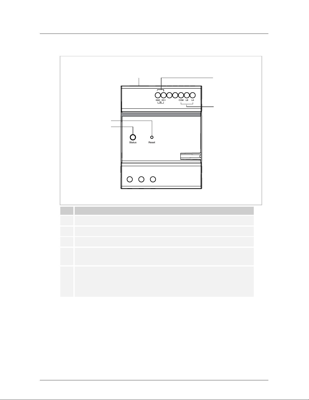
5.1 Device type ...............................................................................................................................6
5.2 Terminal description...................................................................................................................7
6Technical data......................................................................................................................................8
7Mounting/Installation.............................................................................................................................9
7.1 Requirement for the electrician...................................................................................................9
7.2 Mounting .................................................................................................................................10
8Commissioning...................................................................................................................................11
8.1 Topology .................................................................................................................................11
8.2 Adding devices ........................................................................................................................13
8.3 Accessing the setting screen....................................................................................................15
8.4 Basic information .....................................................................................................................16
8.5 Configure mode.......................................................................................................................17
8.5.1 Pre-configuration mode......................................................................................................... 18
8.5.2 Semi-automatic configuration mode....................................................................................... 22
8.5.3 Manual mode ....................................................................................................................... 27
8.5.4 Editing the existing configuration ........................................................................................... 31
8.6 Parameter settings...................................................................................................................32
8.6.1 Relay status for authorization ................................................................................................ 32
8.6.2 Authorization time out ........................................................................................................... 33
8.6.3 Relay hold time for calling elevator ........................................................................................ 34
8.7 Updating the firmware..............................................................................................................35
8.7.1 Updating the firmware via local PC........................................................................................ 35
8.7.2 Updating the firmware via website ......................................................................................... 37
8.8 Commissioning multiple devices in batches ..............................................................................38
9Cyber security ....................................................................................................................................40
9.1 Disclaimer ...............................................................................................................................40
9.2 Performance and service .........................................................................................................40
9.3 Deployment guideline...............................................................................................................41
9.4 Upgrading................................................................................................................................41
9.5 Backup/restore ........................................................................................................................41
9.6 Malware prevention solution.....................................................................................................41
9.7 Password rule..........................................................................................................................41
10 Notice ................................................................................................................................................42

Table of contents
Product manual
2TMD042300D0005
│
3

Notes on the instruction manual
Product manual
2TMD042300D0005
│
4
1Notes on the instruction manual
Please read through this manual carefully and observe the information it contains. This will
assist you in preventing injuries and damage to property and ensure both reliable operation and
a long service life for the device.
Please keep this manual in a safe place. If you pass the device on, also pass on this manual
along with it. Busch-Jaeger accepts no liability for any failure to observe the instructions in this
manual.
2Safety
Warning
Electric voltage!
Dangerous currents flow through the body when coming into direct or indirect
contact with live components.
This can result in electric shock, burns or even death.
– Disconnect the mains power supply prior to installation and/or disassembly!
– Permit work on the 100-240 V supply system to be performed only by
specialist staff!
3Intended use
As a part of the Busch-Welcome®IP system, this device can only be used with accessories from
the system.

Environment
Product manual
2TMD042300D0005
│
5
4Environment
Consider the protection of the environment!
Used electric and electronic devices must not be disposed of with household
waste.
– The device contains valuable raw materials that can be recycled. Therefore,
dispose of the device at the appropriate collecting facility.
4.1 Busch-Jaeger devices
All packaging materials and devices from Busch-Jaeger bear the markings and test seals for
proper disposal. Always dispose of the packing materials and electric devices and their
components via an authorized collection facility or disposal company.
Busch-Jaeger products meet the legal requirements, in particular the laws governing electronic
and electrical devices and the REACH ordinance.
(EU-Directive 2012/19/EU WEEE and 2011/65/EU RoHS)
(EU-REACH ordinance and law for the implementation of the ordinance (EG) No.1907/2006)

Product description
Product manual
2TMD042300D0005
│
6
5Product description
5.1 Device type
Article
number Product ID Product name Colour Size (DxHxW)
Unit: mm
H8308-03 2TMA130160W0042 IP Elevator controller Grey 90 x 72 x 65

Product description
Product manual
2TMD042300D0005
│
7
5.2 Terminal description
No. Function
1System power supply connector
2RS485 connector
3LAN (PoE)
4
Reset button
Press and hold this button for 10 seconds at any time to restore the device to the factory
defaults. The status indicator will go off for 3 seconds then start to flash slowly.
5
Status indicator
■On: the device is working normally
■Off: the device is not powered on
■Flashing quickly: the device is working abnormally (e.g. IP conflict, no MAC address)
■Flashing slowly: the device has not obtained the signature
1
2
3
4
5

Technical data
Product manual
2TMD042300D0005
│
8
6Technical data
Designation Value
Rating voltage 24 V
⎓
Operating voltage range 20-27 V
⎓
Rating current 24 V
⎓
, 60 mA
Operating temperature -20 °C…+55 °C
Storage temperature -20 °C…+70 °C
PoE standard IEEE802.3 af

Mounting/Installation
Product manual
2TMD042300D0005
│
9
7Mounting/Installation
Warning
Electric voltage!
Dangerous currents flow through the body when coming into direct or indirect
contact with live components.
This can result in electric shock, burns or even death.
– Disconnect the mains power supply prior to installation and/or disassembly!
– Permit work on the 100-240 V supply system to be performed only by
specialist staff!
7.1 Requirement for the electrician
Warning
Electric voltage!
Install the device only if you have the necessary electrical engineering
knowledge and experience.
– Incorrect installation endangers your life and that of the user of the electrical
system.
– Incorrect installation can cause serious damage to property, e.g. due to fire.
The minimum necessary expert knowledge and requirements for the installation
are as follows:
– Apply the "five safety rules" (DIN VDE 0105, EN 50110):
1. Disconnect
2. Secure against being re-connected
3. Ensure there is no voltage
4. Connect to earth and short-circuit
5. Cover or barricade adjacent live parts.
– Use suitable personal protective clothing.
– Use only suitable tools and measuring devices.
– Check the type of supply network (TN system, IT system, TT system) to
secure the following power supply conditions (classic connection to ground,
protective grounding, necessary additional measures, etc.).

Mounting/Installation
Product manual
2TMD042300D0005
│
10
7.2 Mounting

Commissioning
Product manual
2TMD042300D0005
│
11
8Commissioning
8.1 Topology
Outdoor station
Outdoor station type Support "Elevator control" or not?
IP touch 5 outdoor station Yes, but its firmware version should be V1.32 or higher
IP keypad outdoor station Yes, but its firmware version should be V1.32 or higher
IP pushbutton outdoor station Yes, but its firmware version should be V1.32 or higher
Mini outdoor station No
Indoor station
Indoor station type Support "Elevator control" or not?
IP touch 7 Yes, but its firmware version should be V2.34 or higher
IP touch 10 Yes, but its firmware version should be V2.27 or higher
Audio IP No
Smart Access Control
Smart Access Control type Support "Elevator control" or not?
Smart Access Control Pro Yes, but its firmware version should be V6.23 or higher

Commissioning
Product manual
2TMD042300D0005
│
12
Capacity
One block supports a maximum of 4 IP elevator controllers.
One IP elevator controller supports a maximum of 16 relay modules.
One relay module supports a maximum of 16 channels.

Commissioning
Product manual
2TMD042300D0005
│
13
8.2 Adding devices
Precondition
■All the devices to be added manually must be powered on.
■None of the devices to be added manually should be signed by another "Smart Access
Point". If the devices have been signed by another "Smart Access Point", you need to clear
the signature e.g. resetting the device to the factory defaults.
Adding the devices manually
Please follow the steps below:
[1] On the configuration screen, click "Door entry system" to access the corresponding screen.

Commissioning
Product manual
2TMD042300D0005
│
14
[2] On the "Door Entry System" screen, click "Add device".
[3] Select "Elevator Controller" from the drop-down list.
[4] Enter the block number.
[5] Enter the device number.
[6] Enter the serial number.
[7] Click "Save".
Note
If the device has already been signed by another "Smart Access Point", it will not
be signed.

Commissioning
Product manual
2TMD042300D0005
│
15
8.3 Accessing the setting screen
Please follow the steps below:
[1] On the "Door Entry System" screen, click "Elevator Controller".
[2] Click the designated elevator controller to access the corresponding screen.
[3] Click "Settings" to access the settings screen.
[4] If you have already saved a configuration, click "Saved Configuration" to edit the existing
settings directly.

C
ommissioning
Product manual
2TMD042300D0005
│
16
8.4 Basic information
On the "Settings" screen:
No. Description
1 Display the physical address of the device (block no. & device no.).
2Display the serial no. of the device.
3 Display the firmware version and MCU version of the device.

Commissioning
Product manual
2TMD042300D0005
│
17
8.5 Configure mode
There are 3 optional configuration modes.
Pre-configuration
mode
Semi-automatic
configuration mode Manual mode
Lowest floor level
below ground -3 -3 -7
Highest floor level
above ground 18 32 63
Maximum number of
elevators supported 1according to actual
requirement
according to actual
requirement
Maximum number of
outdoor stations
supported
64 64 64
Call elevator according
to the room number No No Yes

Commissioning
Product manual
2TMD042300D0005
│
18
8.5.1 Pre-configuration mode
This mode is usually used for a simple project, e.g. a building which has not more than 18 floors
above the ground floor.
This mode can guide you through completion of all configuration work step by step.
User case 1
Question Answer
Which floors need to support the
elevator control? -1, 1, 2, 3, 4, 5, 6
Where are the outdoor stations
installed?
Outdoor station 1 is installed on floor 1
Outdoor station 2 is installed on floor -1
Is the "call elevator from indoor
station" function needed? Yes
The following steps below are based on the user case 1, please adjust the settings according to
the actual case:
[1] On the "Settings" screen, select "Preconfigured" from the drop-down list.

Commissioning
Product manual
2TMD042300D0005
│
19
[2] On the "Floors Selection" screen:
■Select the designated floors needed to support the "elevator control" function.
– When a floor is pressed, the selection will be visual.
– Click "Select all" to select all floors
– Click "Inverse" to invert the selection of existing floors.
Note
Please note that the first floor above the ground will be indicated with the
number 1, and the one right below, with the number -1.
■Click "Next".

Commissioning
Product manual
2TMD042300D0005
│
20
[3] On the "OS Setup" screen:
■Select the floor for each outdoor station to be installed
– Click "Add an outdoor station", then set the device no. and the floor no .for the outdoor
station installed.
– Click " " to remove the existing outdoor station.
■Click "Next".
[4] On the "IS Setup" screen:
■Select "Enable" to allow the Indoor Station to call the elevator from the apartment. This will
allow the resident to request the elevator even when no external calls have been triggered.
■Click "Next".
Table of contents
Other Busch-Jaeger Controllers manuals