M-system PATLABOR IT50SRE User manual

5-2-55, Minamitsumori, Nishinari-ku, Osaka 557-0063 JAPAN
Phone: +81(6)6659-8201 Fax: +81(6)6659-8510 E-mail: info@m-system.co.jp
EM-2379 Rev.3 P. 1 / 6
INSTRUCTION MANUAL
PATLABOR™
BEFORE USE ....
Thank you for choosing M-System. Before use, please check
contents of the package you received as outlined below.
If you have any problems or questions with the product,
please contact M-System’s Sales Office or representatives.
■PACKAGE INCLUDES:
Tower Light .........................................................................(1)
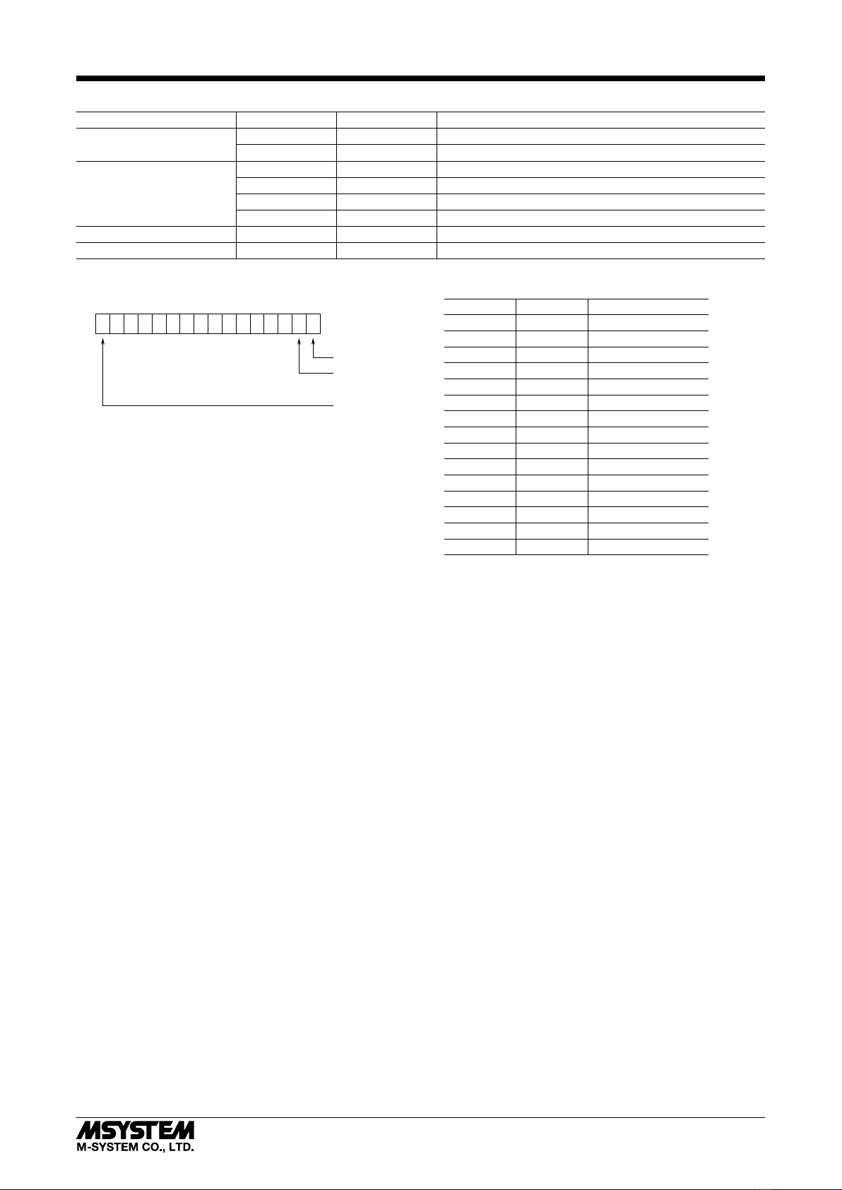
■MODEL NO.
Confirm Model No. marking on the product to be exactly
what you ordered.
■INSTRUCTION MANUAL
This manual describes necessary points of caution when
you use this product, including installation, connection and
basic maintenance procedures.
POINTS OF CAUTION
■CONFORMITY WITH EU DIRECTIVES
•This equipment is suitable for Pollution Degree 3 and
Installation Category III (24V DC power model), or Pol-
lution Degree 2 and Installation Category II (100 – 240V
AC power model). Reinforced insulation (network to
power: 300V) is maintained. Prior to installation, check
that the insulation class of this unit satisfies the system
requirements.
•Altitude up to 2000 meters.
•The equipment must be installed such that appropriate
clearance and creepage distances are maintained to con-
form to CE requirements. Failure to observe these re-
quirements may invalidate the CE conformance.
•The actual installation environments such as panel con-
figurations, connected devices, connected wires, may af-
fect the protection level of this unit when it is integrated
in a panel system. The user may have to review the CE
requirements in regard to the whole system and employ
additional protective measures to ensure the CE conform-
ity.
•The equipment is intended to be installed in a industrial
environment defined by EN 60947-5-1.
■POWER INPUT RATING & OPERATIONAL RANGE
•Locate the power input rating marked on the product and
confirm its operational range as indicated below:
100 – 240 V AC rating: 85 – 264 V, 47 – 66 Hz,
approx. 5.5 VA at 100 V
approx. 7 VA at 200 V
approx. 8 VA at 240 V
24 V DC rating: 24 V ±10 %, approx. 3 W
■GENERAL PRECAUTIONS
•Before you remove the unit or mount it, turn off the power
supply and input signal for safety.
•The unit must not be subjected to external force.
•Do not rub the unit with organic solvent like paint thin-
ner.
■ENVIRONMENT
•Indoor use.
•Do not install the unit where it is subjected to continuous
vibration. Do not subject the unit to physical impact.
•Environmental temperature must be within -10 to +55°C
(14 to 131°F) with relative humidity within 30 to 90% RH
in order to ensure adequate life span and operation.
•Mount the unit on a flat and robust plate.
•Lamps are omnidirectional.
•The buzzer sound is directional in front of the unit.
■INGRESS PROTECTION (IP65)
•The IP code is conformable when the unit is mounted ver-
tically, and the control panel cover is locked. The com-
partment, where connectors are located, is not protected.
•When opening the control panel cover, avoid humidity
and dust penetration. Dry and clean it if condensation is
formed, and close the cover locking tightly.
•In order to protect ingress of water or dust into the bot-
tom compartment, mount the unit on the flat plane, and
be sure that the gasket does not roll back or dust is not
on the gasket.
■WIRING
•Do not install cables close to noise sources (relay drive
cable, high frequency line, etc.).
•Do not bind these cables together with those in which
noises are present. Do not install them in the same duct.
■AND ....
•The unit is designed to function as soon as power is sup-
plied, however, a warm up for 10 minutes is required for
satisfying complete performance described in the data
sheet.
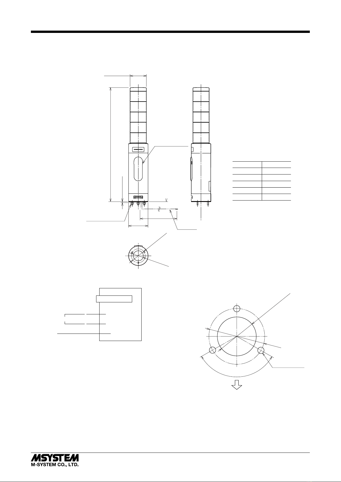
ETHERNET TOWER LIGHT
(small size, 50 mm dia., Modbus/TCP, 1 - 5 layers) MODEL IT50SRE

IT50SRE
5-2-55, Minamitsumori, Nishinari-ku, Osaka 557-0063 JAPAN
Phone: +81(6)6659-8201 Fax: +81(6)6659-8510 E-mail: info@m-system.co.jp
EM-2379 Rev.3 P. 2 / 6
COMPONENT IDENTIFICATION
5
4
3
2
2
1
0
9
8
7
6
5
4
3
1
0
9
8
7
6
5
4
3
2
1
0
9
8
7
6
Power
Run
Link COL
Link100
Power Link COL
Run Link100
Mode Ethernet
Modular Jack
IP Address Reset
Lamp 1
■BOTTOM VIEW
Lamp 2
Lamp 3
Lamp 4
Buzzer Aperture
Status Indicator LED
DIP SW
■FRONT VIEW (with the cover open)
FRONT
Gasket
Lamp 5
■STATUS INDICATOR
ID COLOR FUNCTION
Power Green Turns on when the power is sup-
plied normally.
Run Green Turns on in normal communications
conditions.
Link Green Turns on in Link status.
Link100 Green Blinks when the module is
transmitting/receiving. *1
COL Green Blinks in case of collisions.
*1. Used only in 100BASE link. Dark in 10BASE link.
■OPERATING MODE
(*) Factory setting
• Lamp Blinking Frequency: Mode-1
Mode-1 LAMP BLINKING FREQUENCY
OFF Approx. 2 Hz (*)
ON Approx. 10 Hz
• Buzzer Intermittent Frequency: Mode-2
Mode-2 BUZZER INTERMITTENT FREQUENCY
OFF Approx. 2 Hz (*)
ON Approx. 10 Hz
• Buzzer Volume: Mode-3, Mode-4
Mode-3 Mode-4 BUZZER VOLUME
OFF OFF Quiet (*)
OFF ON Middle
ON OFF Loud
ON ON Maximum
• Output at the Loss of Communication: Mode-6
Mode-6 OUTPUT AT THE LOSS OF COMMUNICATION
OFF Reset the output (turned off) (*)
ON Hold the output (maintains the last data
received normally)
Note: Be sure to set unused Mode-5 and 7 through 8 to OFF.
■IP ADDRESS RESET
IP RESET SW IP ADDRESS RESET
OFF Operating (*)
ON IP address returns to factory default
(after restarting the unit)
(*) Factory setting
Note: Other network settings are also reset to default.
■CONFIGURATOR SETTING
Some network settings are available using the PC Configu-
rator Software.
Factory default IP address is 192.168.0.1. IP address is
configurable using the ITCFG on a PC. In case that the
changed IP address is not able for establishing a connection,
reset the IP address to default and try to connect again.
Note: Refer to the ITCFG users manual for its instructions.

IT50SRE
5-2-55, Minamitsumori, Nishinari-ku, Osaka 557-0063 JAPAN
Phone: +81(6)6659-8201 Fax: +81(6)6659-8510 E-mail: info@m-system.co.jp
EM-2379 Rev.3 P. 3 / 6
TERMINAL CONNECTIONS
Connect the unit as in the diagram below.
■EXTERNAL DIMENSIONS unit: mm
43±1.5 dia.
(30 dia.)
Lead wires
A±4
Approx.1500
Lamp Layers
1
2
3
4
5
A
224
256
288
320
352
1 – 6 lengths*
3 Bolts and Nuts (M4)
Control Panel Cover
*1. Consult M-System for other bolt length.
60±1.5 dia.
50±1.5dia.
■CONNECTION DIAGRAM
V(−)
FE1
POWER Black
U(+)
Gray
RJ-45JACK
Modbus/TCP (Ethernet)
Green/Yellow
FE
■MOUNTING REQUIREMENTS unit: mm
120°
43 dia.
3 Holes (5 dia.)
Front
Wiring Hole 30 dia.*
*Protect wires to prevent scratching them at the edge of the
compartment.

IT50SRE
5-2-55, Minamitsumori, Nishinari-ku, Osaka 557-0063 JAPAN
Phone: +81(6)6659-8201 Fax: +81(6)6659-8510 E-mail: info@m-system.co.jp
EM-2379 Rev.3 P. 4 / 6
CHECKING ETHERNET CONNECTION
■IP ADDRESS
This Tower Light does not support BootP Table Software. The IP Address and Subnet Mask can be configured using the
ITCFG Configurator Software.
The Modbus/TCP Port No. is fixed at 502.
■CHECK WIRING
Connect an Ethernet cable to the RJ-45 connector.
■CHECK INDICATOR
When wiring is correct, Link is turned on.
■CHECK TOWER LIGHT CONNECTION
Enter “ping command” on the Windows MS-DOS as follows:
C:¥WINDOWS>ping ***.***.***.***
(***.***.***.***: Enter IP address in decimal.)
ping ***.***.***.*** with 32 bytes of data:
Reply from ***.***.***.*** : bytes = 32 time < 10ms TTL = 64
Ping statistics for ***.***.***.***
Packets: Sent = 4, Received = 4, Lost = 0 (0% loss)
Replies in case of normal connection are as shown above. If the connection cannot be established normally due to e.g. wrong
IP address, other replies such as ‘timeout’ will be received.
■CHECK CONNECTION TO THE APPLICATION SOFTWARE
Check Point 1: Link indicators
When normal connection is established, the front Link is turned on regardless of data sending/receiving status. Check the
network in case that the indicator is not on.
Check Point 2: Run indicator
A green light turns on at the Run indicator in normal data sending/receiving.
Check Point 3: Link100 indicator
A green light blinks at the Link100 indicator in normal data sending/receiving for 100BASE link.

IT50SRE
5-2-55, Minamitsumori, Nishinari-ku, Osaka 557-0063 JAPAN
Phone: +81(6)6659-8201 Fax: +81(6)6659-8510 E-mail: info@m-system.co.jp
EM-2379 Rev.3 P. 5 / 6
MODBUS FUNCTION CODES & SUPPORTED CODES
■Data and Control Functions
CODE NAME
01 Read Coil Status X Digital output from the slave (read/write)
02 Read Input Status X Status of digital inputs to the slave (read only)
03 Read Holding Registers General purpose register within the slave (read/write)
04 Read Input Registers X Collected data from the field by the slave (read only)
05 Force Single Coil X Digital output from the slave (read/write)
06 Preset Single Registers X General purpose register within the slave (read/write)
07 Read Exception Status
08 Diagnostics
09 Program 484
10 Poll 484
11 Fetch Comm. Event Counter Fetch a status word and an event counter
12 Fetch Comm. Event Log A status word, an event counter, a message count and a field
of event bytes
13 Program Controller
14 Poll Controller
15 Force Multiple Coils X Digital output from the slave (read/write)
16 Preset Multiple Registers General purpose register within the slave (read/write)
17 Report Slave ID Slave type / ‘RUN’ status
18 Program 884/M84
19 Reset Comm. Link
20 Read General Reference
21 Write General Reference
22 Mask Write 4X Register
23 Read/Write 4X Register
24 Read FIFO Queue
■Exception Codes
CODE NAME
01 Illegal Function X Function code is not allowable for the slave
02 Illegal Data Address X Address is not available within the slave
03 Illegal Data Value X Data is not valid for the function
04 Slave Device Failure
05 Acknowledge
06 Slave Device Busy
07 Negative Acknowledge
08 Memory Parity Error

IT50SRE
5-2-55, Minamitsumori, Nishinari-ku, Osaka 557-0063 JAPAN
Phone: +81(6)6659-8201 Fax: +81(6)6659-8510 E-mail: info@m-system.co.jp
EM-2379 Rev.3 P. 6 / 6
MODBUS I/O ASSIGNMENTS
ADDRESS DATA TYPE DATA
Coils (0X) 1 – 16 Digital Output (lamp, buzzer)
17 – 32 Reserved (unused)
Inputs (1X) 1 – 16 Reserved (unused)
17 – 32 Reserved (unused)
33 – 48 Reserved (unused)
49 – 64 Reserved (unused)
Input Registers (3X) 1 – 48 ---- Reserved (unused)
Holding Registers (4X) 1 – 48 ---- Reserved (unused)
■ OUTPUT DATA
Output 0
Output 1
Output 2
Output 3
Output 4
Output 5
Output 6
Output 7
Output 8
Output 9
Output 10
Output 11
Output 12
Output 13
Output 14
Output 15
Lamp 1
Lamp 2
Lamp 3
Lamp 4
Lamp 5
Buzzer
Lamp 1
Lamp 2
Lamp 3
Lamp 4
Lamp 5
Buzzer
0: Off, 1: On
0: Off, 1: On
0: Off, 1: On
0: Off, 1: On
0: Off, 1: On
0: Off, 1: Continuous
0: Off, 1: Blinking
0: Off, 1: Blinking
0: Off, 1: Blinking
0: Off, 1: Blinking
0: Off, 1: Blinking
0: Off, 1: Intermittent
0
15
Output 0
Note: If “On” (Continuous) and “Blinking” (Intermittent)
are set simultaneously for a single lamp (buzzer),
“Blinking” (Intermittent) is disabled.
Output 1
:
:
Output 15
Table of contents
Other M-system Lighting Equipment manuals
Popular Lighting Equipment manuals by other brands

Endless Pools
Endless Pools FastLane owner's manual

Home Accents Holiday
Home Accents Holiday C7-5L-STA1-M Use and care guide

Emergi-Lite
Emergi-Lite Lux-Ray LED manual

Vision & Control
Vision & Control LDLF60x540-R633/UDC Instructions for use

Angler
Angler Quick-Open Deep Parabolic Softbox V2 instructions

Chauvet
Chauvet Quad-9 user manual