Endless Pools FastLane User manual

FASTLANE®
By Endless Pools
OWNER’S MANUAL

F a s t l a n e®Swi Unit Installation
1
Section 1 GENERAL OVERVIEW OF AN ENDLESS POOL FASTLANE
The Fastlane®swimming machine by Endless Pools is a hydraulically-powered system that creates a
smooth, adjustable-speed swim current in a conventional pool. The Fastlane has been fabricated with the
finest, most durable materials and designed to meet the most stringent safety standards including VGB
2008. The swim current produced is wider than your body and deeper than your stroke — far superior to
currents created by one or more jets. Two 3/8" (9,5mm) hydraulic hoses carrying a non-food grade,
biodegradable vegetable oil run between the hydraulic Power Unit and the Fastlane Swim Unit, thus
eliminating the need for electricity poolside. When pumped at high pressure, this hydraulic fluid creates a
swim current by turning the shaft of a submerged stainless steel hydraulic motor in the Fastlane Swim
Unit, which in turn rotates a 16" (40,6cm) diameter propeller. The Power Unit is activated using a 3-button
radio frequency remote control that can turn the unit on and off and adjust the speed. It is best if the Power
Unit is within 25' (7,6m) of the Swim Unit to minimize pressure loss. An optional 6" (15,2cm) LED swim
pace display is available to monitor your speed. Also, customers often place our swim mirror on the
bottom of the pool to observe their swim stroke.
Note: all of the 316L stainless steel screws provided for the assembly of this unit should be tightened to
the recommended 25 in-lbs of torque.
= Wall Mount Fastlane = Deck Mount Fastlane
The Fastlane can be mounted one of two wa s:
The Wall Mount Fastlane fastens to the wall of the pool using the bracket provided. Two 1 1/2" (38mm)
PVC pipe which serve as conduits for the hydraulic hoses run under the pool deck to a
remotely located, 5-horsepower, hydraulic Power Unit, as shown in Figure 1.1.
The Deck Mount Fastlane fastens to the pool deck using the hanger bracket provided. The two hydraulic
lines then run back to the remotely located, 5-horspower, hydraulic Power Unit. The hydraulic hoses can
be run through a conduit or run aboveground, as shown in Figure 1.2.
D
W
Fig 1.1
Fig 1.2
W
D

F a s t l a n e®Swi Unit Installation
2
Section 2 CHOOSING A LOCATION FOR YOUR FASTLANE
The Fastlane can fit in virtually any swimming pool. For optimal water flow, we recommend that you allow
at least 12 feet (3,7m) between the wall on which the Fastlane is installed and the opposing wall in line with
the Swim Unit. The Fastlane has more than 9 square feet (.83m2) of water intake to eliminate any entrapment
hazards. The water depth where the Fastlane is installed must be at least 35" (89cm) deep. In addition, the
Fastlane must be installed no closer than 24" (61cm) from any adjacent wall as shown in Figure 2.1, Mini-
mum Clearance Guidelines.
When choosing a location for your Fastlane, you should also consider the route for the hydrualic hoses to
run back to the Power Unit. The Power Unit needs to sit on a solid, level surface, preferably not on wet
ground, and requires a 30-amp, 220-volt GFCI electric service. For U and international electrical require-
ments, please refer to Section 11. The optional Outdoor Power Unit with Weather Guard may be located
outside, but should not be subject to driving rain. Typically, the Power Unit is located with the other pool
equipment and, if possible, long hydraulic runs should be avoided because of pressure loss. If you wish to
have a run greater than 25' (7,6m), you must transition from 3/8" (9,5mm) hydraulic hoses to 1/2"
(12,7mm) run hoses with the addition of a junction box as reviewed in Section 5.
Section 3 RECEIVING YOUR FASTLANE
The Endless Pools Fastlane is comprised of a minimum of five (5) parcels. Additional parcels may be
shipped as appropriate. All items will be shipped via UPS Ground.
Items shipped UPS
Parcel 1: Fastlane Swim Unit – propulsion housing
Parcel 2: Fastlane Swim Unit – base with pre-installed,
25 feet (7,7m) of hydraulic hoses, grab bar
Parcel 3: 5-hp Power Unit with 2 Wireless Remote Controls and Antenna located inside the controller
(Heavy Box) Note: If the Outdoor Power Unit was purchased as an option, the Weather Guard
will come pre-assembled to the Power Unit.
Parcel 4: Five (5) Gallons of Hydraulic Fluid (19L) (Non-Food Grade Vegetable Oil)
Parcel 5: Accessories it (Wall Mount or Deck Mount)
Wall Mount Accessories Kit
- 2 8 JIC Female x 6 JIC Male Adapter
- 14 Screw, #10 x 3/4" (19mm), SMS, Blunt Tip, Phil Truss Head,
Type B Point, Type A Thread, Passivated 316SS
- 16 Screw, #10 x 1" (25mm), SMS, Blunt Tip, Phil Truss Head,
Type B Point, Type A Thread, Passivated 316SS
- 1 Zinc Sacrificial Anode
- 2 Protective Hat Channels
- 1 Top Lid, Acrylic Pool Propulsion Housing
- 16 Screw, 316 SS, M/S, Type 1 Phillips Truss Head, 10-32 x 1" (25mm)
- 6 Nut, 316 SS, Lock, Hex, with nylon insert, 10-32
Fig 2.1
Mini u Clearance Guidelines
WD
WD
W

F a s t l a n e®Swim Unit Installation
3
Deck Mount Accessories Kit
- 1 Top Lid, Sapphire, Acrylic Pool Propulsion Housing
- 2 Protective Hat Channels
- 1 Deck Plate Hanging Bracket
- 1 Deck Plate Cover
- 1 Deck Plate Bottom
- 1 Bonding Lug, 3/16" (4,8mm) Stud Size
- 1 Screw, 316 SS, M/S, Phillips, Truss, 10-32 x 3/8" (9,5mm)
- 2 8 J C Female x 6 J C Male Adapter
- 8 Masonry Screws, 3/16 x 2-1/4" (4,7mm x 57mm), Phillips Flat Head, Blue Coated Steel
- 4 Hose Clip
- 1 Bit, Masonary, 5/32" (4mm)
- 18 Screw, #10 x 3/4" (19mm), SMS, Blunt Tip, Phil Truss Head,
Type B Point, Type A Thread, Passivated 316SS
- 8 Screw, 316L SS, M/S, Phillips Truss 10-32 x 1/2" (12,7mm)
- 16 Screw, #10 x 1" (25mm), SMS, Blunt Tip, Phil Truss Head,
Type B Point, Type A Thread, Passivated 316SS
- 1 Zinc Sacrificial Anode
- 16 Screw, 316 SS, M/S, Type 1 Phillips Truss Head, 10-32 x 1" (25mm)
- 6 Nut, 316 SS, Lock, Hex, with nylon insert, 10-32
he Following two packages will be included ONLY if a Wall Mount Fastlane was purchased:
Parcel 6: Wall Mount Bracket Assembly
Optional Equipment
• Outdoor Power Unit with Weather Guard
• Floor Mirror
• Swim Pace Display
Section 4 WALL MOU T BRACKET
NO E: Please read instructions fully before beginning bracket installation.
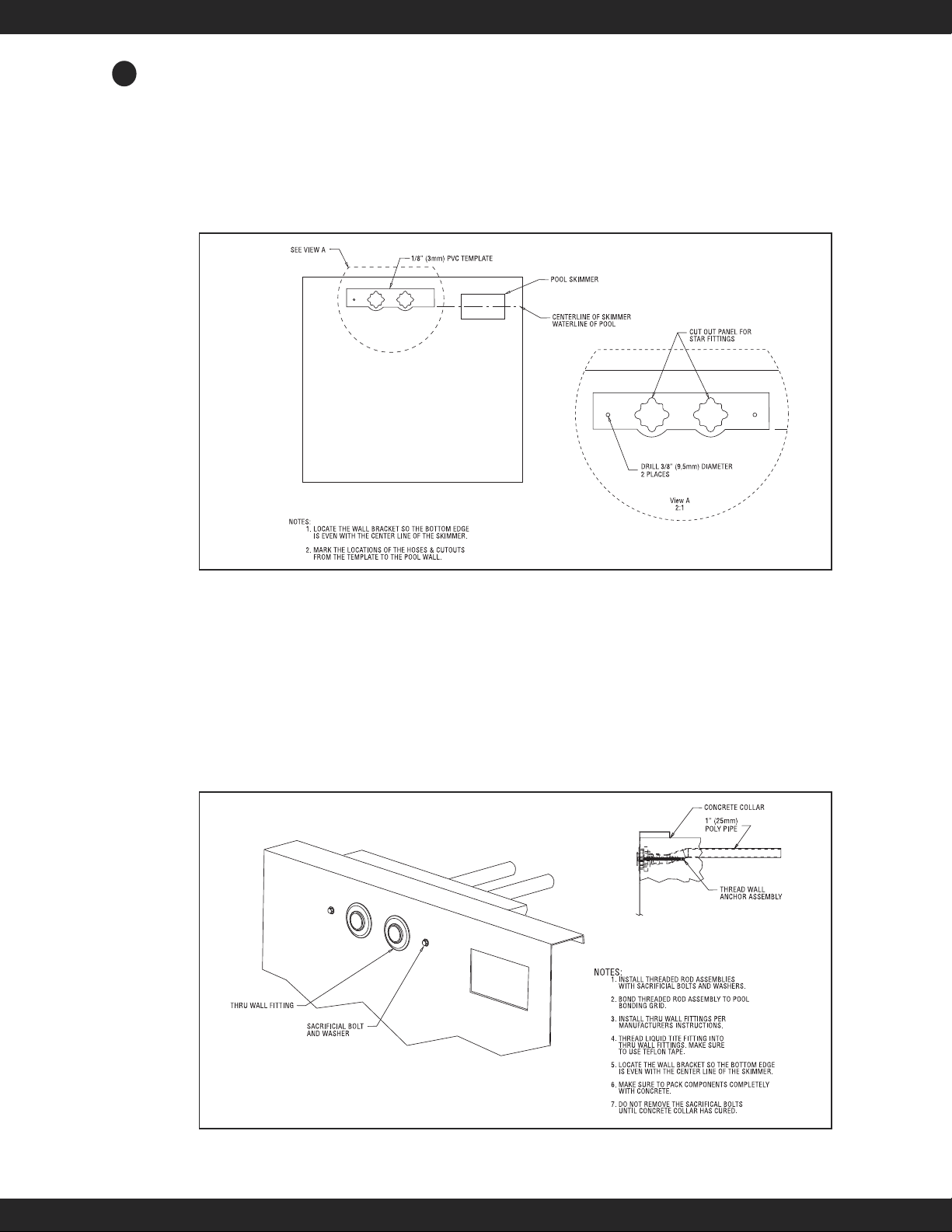
4.A. Gunite/Concrete Pool
f the pool being constructed is gunite or concrete, please follow the instructions below.
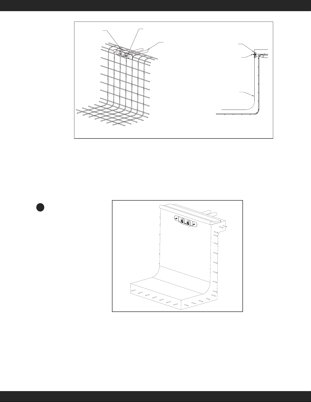
Parcel 6 includes the Wall Mount Fastlane bracket for concrete or gunite pools. (refer to Photo 4.A.1)
- 1 Gunite/Fiberglass Wall Bracket PVC Plate
- 1 Screw, 316L SS, M/S, Phillips Truss 10-32 x 1-1/2" (38mm)
- 1 Bonding Lug, 3/16" (4,8mm) Stud Size
- 1 Washer, Flat, #10 x 7/16OD x .062 Thick, 316 SS
- 1 Nut, Jam, 10-32, 316SS
- 1 Nut, 316 SS, Lock, Hex, w/ Nylon nsert, 10-32
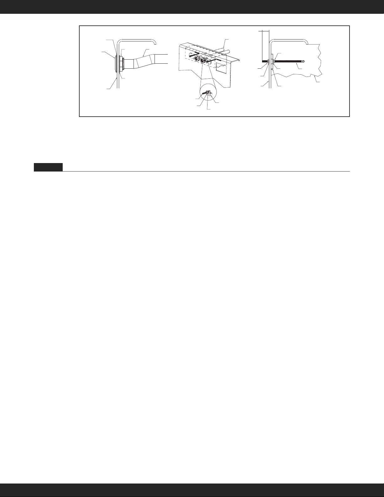
- 2 Threaded Rod, 3/8-16, 316 SS, 10.25 in long (26cm)
- 6 Nut, Jam, 3/8-16, 316SS
- 6 Washer, 316 SS, Flat, 3/8" x 7/8" (9,5mm x 22mm)
- 2 Washer, 316 SS, Lock, Medium Split, 3/8" (9,5mm)
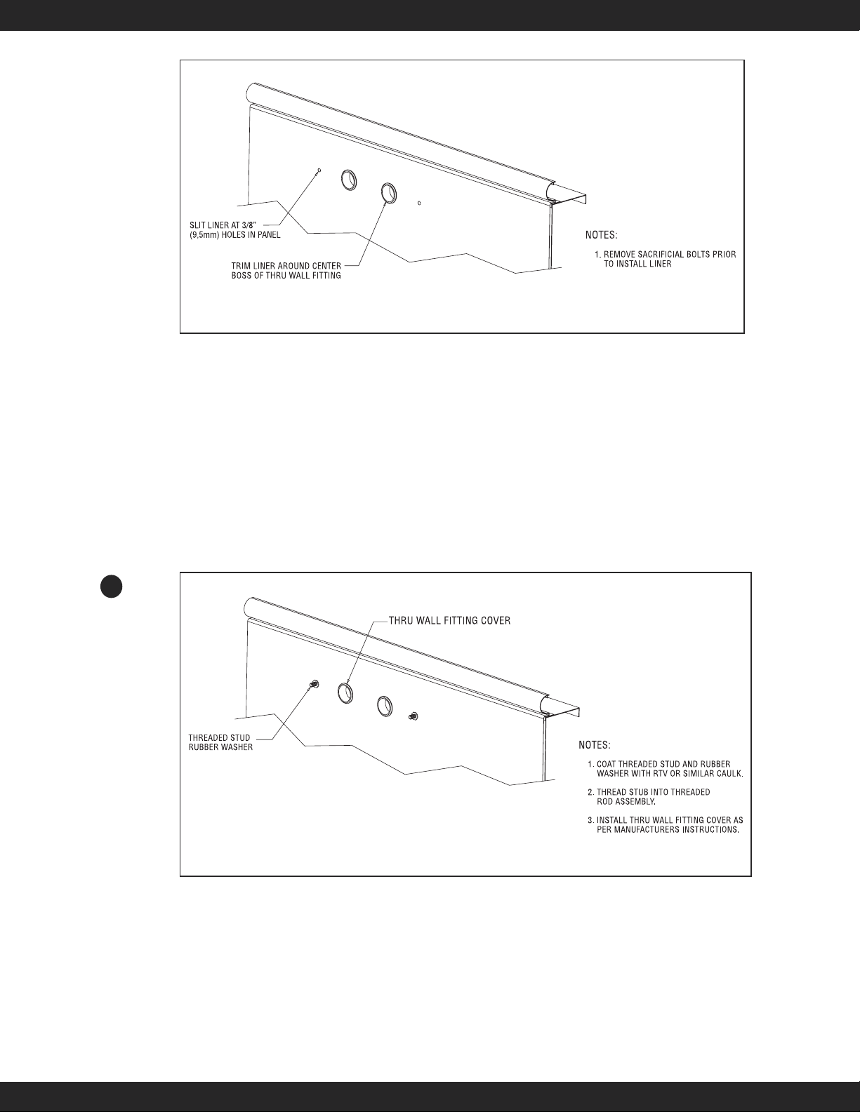
- 2 Thruwall Fitting, PVC, Schedule 40, Round Cutout, 1-1/2" (38mm) FSlip
- 2 Bushing, PVC, Reducer, 1-1/2" (38mm) MPT x 1" (25,4mm) FPT
- 2 Cord Grip Liquid Tite Fitting, PVC, 1" (25,4mm) NPT, fitting only
D
WD
W
W

F a s t l a n e®Swim Unit Installation
4
Secure the thru-wall fittings to the bracket as shown in Fig 4.1. The rubber gasket should be between the
thru-wall and the bracket on the poolside of the bracket and the cork gasket should be between the bracket
and the locknut on the outside. Tighten the lock nut with a pair of channel locks or strap wrench.
Using PVC cleaner and PCV cement, glue the conduit into the backside of the thru-wall assemblies.
Make sure that the threaded rod is protruding from the front of the bracket approximately 1-1/4" - 1-1/2"
(31,8mm x 38mm). There should be a washer and jam nut on both sides of the threaded rod, securing it to
the bracket.
Verify the bonding lug is attached to the backside of the bracket using the 10-32 machine screw. On the
front side of the bracket, a 10-32 washer and jam nut should be threaded onto the 10-32 bonding screw.
The bracket is to be installed into the pool wall as shown in Figure 4.2 so that the two mounting rods are
1-1/2" (38mm) above the intended waterline for the pool, which is typically halfway up the skimmer. (The
bottom edge of the Wall Mount Bracket will sit along the pool’s intended waterline.) The rods penetrate
1-1/4" to 1- 1/2" (31,8mm x 38mm) into the finished pool and will be used to hang the Wall Mount Fast-
lane. These rods must be tied back to the rebar of the bond beam in the pool and, once encased in concrete,
will serve as a suitable hanger. Additionally, a #8 or larger, solid copper bonding wire must be connected
from the pool bonding grid to the bonding lug located on back of the wall mount bracket.
Fig. 4.1
Thru-Wall Fitting
Cork Gasket
3/8" (9,5mm) Stainless Steel
Threaded Mounting Rod
(firmly secure rod to rebar grid)
Thru-Wall Fitting
1-1/2" (38mm) MPT x 1" (25mm) FPT
Bushing Reducer
1" (25mm)
Liquid Tight Fitting
3/8" (9,5mm) Stainless
Steel Jam Nut
3/8" (9,5mm) Stainless
Steel Jam Nut
3/8" (9,5mm) Stainless
Steel Washer
3/8" (9,5mm) Stainless
Steel Washer
3/8" (9,5mm) Stainless
Steel Washer
3/8" (9,5mm) Stainless Steel
Lock Washer
3/8" (9,5mm) Stainless
Steel Nut
10-32 Machine Screw
Bonding Lug
10-32 Washer
10-32 Jam Nut
10-32 Lock Nut
Bracket Plate
1-1/2" 38mm) Flexible PVC
(supplied by others)
Thru-Wall Fitting
Locknut
Thru-Wall Fitting
Rubber Gasket
(2nd rubber gasket is
not used)
W

F a s t l a n e®Swim Unit Installation
5
Level and position the bracket so that the PVC surface of the bracket plate will be flush with the finished
surface of the pool wall as shown in Figures 4.2 and 4.3. The area below the bracket plate should be no
more than 5 degrees less than vertical down to at least 35" (89cm) below the waterline. The Fastlane is
21" (53,3cm) wide. Consequently, the 21" (53,3cm) section of wall where the bracket is located should
be straight or near straight. Any variations from this requirement should be discussed with your design
representative. Additionally, it is imperative that the Fastlane not be installed less than 24" (61cm) from
an adjacent wall to allow for proper water flow. Please refer back to Figure 2.1, Minimum Clearance
Guidelines, for clarification.
Unroll the flexible PVC from the wall mount bracket back to the Power Unit. Each length of flex PVC
must be no longer than 21 feet (6,4m) and should exit the ground near the Power Unit.
f the distance between the wall mount bracket and the Power Unit is greater than 25 feet (7,6m) then a
junction box and additional flex pipe must be employed. n this case, the flex pipe between the wall mount
bracket and the junction box must be 24 feet 6 inches 7,5m). This will allow the hydraulic hose attached to
the Fastlane terminate just inside the junction box. See section 5 for additional information.
Prior to shooting gunite, it is critical that the opening of the each thru-wall, the bonding screw, and the
threaded rod covered. No gunite can be embedded in these areas.
WIRE THREADED
ROD TO REBAR
FLEXIBLE PIPE TO
ABOVE GROUND
AT POWER UNIT
BOND FROM POOL GRID
TO BACKSIDE OF PLATE
CENTERLINE OF BRACKET
1 1/2" ABOVE CENTER
LINE OF SKIMMER
FINISHED WALL
OF POOL
WALL PLATE EVEN
WITH POOL WALL
Fig. 4.2
Fig. 4.3
W

F a s t l a n e®Swim Unit Installation
6
4.B. Steel/Polymer Panel Pool with a Vinyl Liner
f the pool being constructed is steel/polymer panel with a vinyl liner, please follow the instructions below.
Remove the star thru-wall fittings and threaded rod pieces with hex coupling nut attachments from the 1/8"
(3mm) -thick, grey PVC template. Position the PVC template where the Fastlane will attach to the pool
wall and align the bottom of the template with the expected water level in the pool (which will typically be
located at the centerline of the skimmer) as shown in Figure 4.4. Use duct tape, perhaps wrapped over the
top flange, to temporarily adhere the PVC template to the pool wall. Be certain that the PVC template is
level in the pool. Trace the outline of the star thru-wall fittings and threaded rod hole penetrations that are
cut in the PVC template onto the pool wall. Remove the duct-taped PVC template from the pool wall.
Cut (or punch) the openings for the star thru-wall fittings and threaded rod holes. nstall the star thru-wall fit-
tings with the holes for the cover at 12, 3, 6 and 9 (clock positions). Apply Teflon thread sealant to the threads
of the 1-1/2" (38mm) MPT x female slip adapters and thread them into the backside of the star thru-wall fit-
ting. Glue the flex PVC conduit into the adapter and run the pipe back to the Power Unit. Refer to Section 5
for additional information. Refer to Section 5 for length of 1-1/2" (38mm) PVC flex pipe. The threaded rod
with hex coupling assembly must now be tightened against the backside of the pool wall. The 3/8" (9,5mm)
jam nuts should be fastened on the threaded rod so that half of the hex coupling is threaded onto the rod and
the other half facing the poolside remains empty. Use the sacrificial 3/8" (9,5mm) bolts and washers to thread
into the hex coupling from the inside of the pool through the hole that was previously drilled in the wall as
shown in Figure 4.5. Tighten the bolts to secure the assembly to the rear of the pool wall.
Fig. 4.4
Fig. 4.5
W

F a s t l a n e®Swim Unit Installation
7
f using rebar in the pool’s collar, tie and bond the bent pieces of threaded rod into the bonded rebar grid.
f no rebar is being used, be sure to bond the threaded rod to the pool’s bonding grid.
Pour the concrete collar around the top flange of the pool securely encasing the threaded rod assemblies
and conduit adapters in place. Even if a bond beam is not being poured for the pool, it is essential for the
operation of the Fastlane that this assembly be securely anchored in concrete. After the concrete has cured,
remove the 3/8" (9,5mm) bolts and install the pool liner. Note: Before beginning the liner installation, be
sure to note the orientation of the star thru-wall holes at 12, 3, 6 and 9 (clock positions) as they will be hid-
den once the liner is hung. (Refer to Figure 4.6.) Make sure there is some water in the bottom of the pool,
giving weight to the liner and pulling it tight, before the holes for the star thru-wall fittings and threaded
rod pieces are cut. When the liner is tight enough, cut the holes. Note: Keep the holes for the threaded rod
as small as possible. Attach the faceplate to the star thru-wall fittings, coat the threaded stud and rubber
washer with RTV or similar caulk, and thread the stub into the threaded rod assembly. (Refer to Figure 4.7.)
4.C. Fiberglass Pool Installation
f the pool being installed is fiberglass, then follow the instructions below:
Remove the thru-wall fittings, bonding lug assembly, and stainless steel hardware from the PVC bracket.
n this application the bracket were serve primarily as a template. Position the bracket on the pool wall
where the Fastlane will be placed. Align the etched mark on the bracket with the expected water line (typi-
cally 1/2 way up the skimmer opening) and make sure that it is level. Temporarily adhere the bracket
(using duct tape or the like) to the pool wall. Trace the outlines of the thru-wall, bonding lug, and threaded
rod openings on to the pool wall.
Fig. 4.6
Fig. 4.7
W

F a s t l a n e®Swim Unit Installation
8
Once the openings are marked, the bracket can be removed from the pool wall. Use a 2-1/2" (63,5mm)
hole saw to drill the thru-wall holes. Use a 3/8" (9,5mm) drill bit for the threaded rod holes. Use a 3/16"
(4,8mm) drill bit for the bonding lug hole.
Cut the center portion out of the bracket using the etched marks in the brackets as a guide. The two end
portions will be used as a washer on the backside of the pool wall.
nsert the threaded rod back into each PVC washer so that the rod will extend into the pool approximately
1-1/2"(38mm). A 3/8" (9,5mm) washer and jam nut should be on inside of the pool and on the backside of
the PVC bracket on the outside of the pool (see Fig 4.10).
The backside of the thru-wall holes may need to be sanded flat so that a proper seal can be made. Place one
of the rubber gaskets onto the thru-wall fitting (the other rubber gasket will not be used in this application.
nsert it into the hole and place the cork gasket onto the fitting on the backside of the pool. Thread the lock
nut onto the fitting onto the thru-wall. The lock nut should be tightened with a pair of channel locks or
strap wrench.
Using PVC cleaner and PCV cement, glue the conduit into the backside of the thru-wall assemblies. Run
the conduit back to the junction box or hydraulic power unit.
Place the bonding lug onto the bonding screw and insert it into the hole in the pool wall so that the threads
of the screw are on the inside of the pool. Place the 10-32 washer and jam nut onto the screw. The bonding
lug must be tied into the pool-bonding grid with a #8 AWG bare copper wire.
FIBERGLASS WALL MOUNT INSTALLATION
Initial Release
Part Name:
LOCATING WALL TEMPLATE
Sheet Number:
Drawing Number:
Part#-Rev
Drawing Not ToScale
Description:
Drawing Name:
Date:
05-25-07
Revision:
A
Dwg By:
KGK
+/- tolerance, +/- tolerance°
Tolerance:(unless otherwise specified) NOT APPLICABLE
Material:
1
200 East Dutton Mill Road., Aston PA 19014
Website:http://www.endlesspools.com
NOTES:
1. LOCATE THE WALL BRACKET SO THE BOTTOM EDGE
IS EVEN WITH THE CENTER LINE OF THE SKIMMER.
2. MARK THE LOCATIONS OF THE HOLES FROM THE TEMPLATE
TO THE POOL WALL.
View A
2:1
CENTERLINE OF SKIMMER
WATERLINE OF POOL
SEE VIEW A
3/8" (9,5mm) PVC TEMPLATE
POOL SKIMMER
SCRIBE HOLES OF TEMPLATE ONTO SHELL.
THEN DRILL A 2-1/2" (63,5mm) Ø HOLE AT THE
CENTERMARK OF EACH SCRIBED HOLE
DRILL 3/16"(4,8mm) DIAMETER
DRILL 3/8" (9,5mm) DIAMETER
2 PLACES
Fig. 4.8
CUT BRACKET BETWEEN NOTCHES
DISCARD MIDDLE SECTION
Fig. 4.9
W

F a s t l a n e®Swim Unit Installation
9
When all of these connections on the outside of the pool are complete, a concrete collar should be pour
around the threaded rod and conduit; this encasement will help secure the Fastlane.
Section 5 JU CTIO BOX A D 1/2" RU HOSES (OPTIO AL)
The wall mount bracket must be attached on the pool wall as explained in the installation instructions in
Section 4. Attached to this bracket are two (2) lengths of 1-1/2" (38mm) PVC flex pipe that run back under
the deck and carry two (2) hydraulic hoses.
f the hydraulic hose runs back to the Power Unit are less than 25' (7,6m), it is not necessary to step up to
1/2" run hose to reduce pressure loss. nstead, the 3/8" (9,5mm) hydraulic hose can run directly to the
Power Unit in the protective conduit.
f the hydraulic hose runs are greater than 25' (7,6m), in order to reduce pressure loss and potential reduction
in speed, a junction box must be used. t is at the junction box where a step up to 1/2" run hose occurs. The
hydraulic hose from the Fastlane Swim Unit to the junction box is 3/8" (9,5mm) and the run hose from the
junction box to the Power Unit is 1/2".
Junction Box Kit (optional) includes:
• One (1) junction box with feet • Two (2) 1-1/2" (38mm) liquid-tite fittings
• Four (4) 1-1/2" (38mm) NPT male/slip female PVC fittings • Six (6) 1-1/2" (38mm) locknuts
• Roll of anti-corrosion tape
• The 1-1/2" (38mm) PVC flex pipe will need to be cut to 24' 6" (7,5mm) from the wall mount bracket to
the junction box.
• Glue the 1-1/2" (38mm) NPT male/slip female fittings on the end of the PVC flex pipe that will connect
to the junction box. Secure the fittings to the junction box with the provided lock nuts.
• To get from the junction box to the Power Unit, run 1-1/2" (38mm) PVC flex pipe.
• Unroll the two (2) lengths of PVC flex pipe from the junction box to the Power Unit. The PVC flex pipe
should exit the ground next to the Power Unit.
• Measure the length of PVC flex pipe. Your 1/2" (12,7mm) run hoses will need to be AT LEAST 4 feet
longer then the length of the PVC flex pipe. Order your 1/2" (12,7mm) run hoses at this time by calling
our Customer Service Department at 800-910-2714.
• Adapters to connect the 1/2" (12,7mm) run hoses to the 3/8" (9,5mm) hoses attached to the Fastlane have
been provided. They can be found in the 1/2" (12,7mm) run hose box and will be attached at a later step
(see section 7).
• f desired, the junction box can be anchored by attaching the feet included with the kit.
Fig. 4.10
(without Thru-Wall Fittings and Conduit)
(without Threaded Rod and Hardware)
Cross Section View
Cross Section View
Fiberglass Shell
Approx 1-1/2"
10-32 Machine Screw
10-32 Flat Washer
10-32 Jam Nut
Bonding Lug
(on the outside of the pool)
Threaded Rod
PVC Washer
(Cut from bracket)
3/8" Jam Nut
3/8" Jam Nut 3/8" Washer
3/8" Washer
Threaded rod embedded
in concrete
Fiberglass Shell
1-1/2" Flex PVC conduit
back to the junction box
or hydraulic power unit
Lock Nut
Cork Gasket
Rubber Gasket
(other gasket unused)
Thru-Wall Fitting 1-1/2" FLex PVC Conduit

F a s t l a n e®Swim Unit Installation
1 0
Section 6 ASSEMBLY OF THE FASTLA E SWIM U IT
6.1 Carefully unpack the swim unit from its boxes. Make sure to remove any hardware packs from the boxes
as well. The packaging can be collapsed and used as a protective surface upon which to assemble the
Fastlane. The foam packing material can be used to wedge under the base to prevent it from tipping over.
6.2 Take care when handling or working with any of the stainless steel components of the swim unit. The
ends can be sharp. The first step is to remove the two circular end caps from each side of the cylindrical
base. There are 3 arced cover strips around the perimeter of the end cap. Unthread the nine screws that
secure the cover strips (3 screws per cover strip). There will be a stainless steel wire connecting the end
cap to the base. The wire can be disconnected to make assembly of the unit easier. f disconnected, the
wire must be re-attached when assembled. Repeat this step for the other side of the stainless steel base.
Carefully set each end cap aside (Fig 6.1).
6.3 Uncoil the two lengths of hydraulic hose that are attached to the cylindrical base. Make sure that the
hoses are seated into their respective notches in the backside of the base (Fig 6.2).
Fig. 6.1
Fig. 6.2
W

F a s t l a n e®Swim Unit Installation
1 1
6.4 Remove the throat from the upper housing. There are two screws on each side of the throat. Pull the
throat off of the housing and set it aside. Pull the vertical water-conditioning grill up and out of the
housing. Pull the horizontal grill out of its track and remove from the housing. Make sure to remove
and discard the wood 2x4 spacer from the bottom of the housing before proceeding (Fig 6.3).
6.5 Carefully remove the protective film encasing the upper housing. Place the upper housing into the
opening of the cylindrical base (Fig 6.4A). The hydraulic hoses connected to the base should be aligned
with the back of the upper housing. Make sure that the stainless steel bonding wire attached to the
motor mount is positioned inside of the upper housing.
6.6 Use the provided stainless steel screws to attach the upper housing to the base. There will be 4 screws
per side (total of 8). On each side of the housing, there will be 3 screws securing the upper housing to
PVC motor mount support and 1 screw attaching the stainless steel reinforcing support to the housing
just above the 3 previous screws (Fig 6.4B).
Fig. 6.3
Fig. 6.4BFig. 6.4A
WD

F a s t l a n e®Swim Unit Installation
1 2
6.7 Carefully lay the Fastlane onto its front face. Run the hydraulic hoses up the back of the upper hous-
ing. The two hat channels will be placed over the hydraulic hoses. Make sure that the mounting hole in
the end of the hat channel is facing up and that the bottom of the hat channel has been inserted into the
notch in the cylindrical base. Use the provided 3/4" (19mm) stainless steel screws to attach the hat
channels to the upper housing. There will be eight screws per hat channel (Fig 6.5).
6.8 Pull any excess hose out of the hat channel.
6.8a) f the hydraulic hoses are to be run up and over the pool deck, then proceed to step 6.9 (Fig 6.6A).
6.8b) f the hydraulic hoses are to go through the pool wall, attach the two hoses to the top of the upper
housing. There are 2 green hose clamps attached to the top of the housing. The screws that
are securing the clamps to the housing will have to be removed in order to secure the hoses to
the clamps (Fig 6.6B).
Fig. 6.5
Fig. 6.6BFig. 6.6A
WD

F a s t l a n e®Swim Unit Installation
1 3
6.9 Slide the horizontal water-conditioning grill back into its track inside the housing. The horizontal grill is
the wider of the two grills (Fig 6.7).
6.10 nstall the stainless steel grab bar to the upper housing using the provided stainless steel screws and
lock nuts. Feed the stainless steel wire attached to the motor mount up through the horizontal grill.
Then feed the wire up between two of the turning vanes. Place the stainless steel wire (from the motor
mount in the base) around the bottom screw on the left side before tightening down on the nut. Place
the second stainless steel wire (that exits the top rear of the upper housing) around another screw be-
fore tightening down on the nut. On the opposite side of the grab bar, secure the provided sacrificial
anode under one of the grab bar mounting screws (Fig 6.8).
Fig. 6.7
Fig. 6.8
WD

F a s t l a n e®Swim Unit Installation
1 4
6.11 Reattach the throat (removed in step 4) to the upper housing. Again, there will be 2 screws on
either side of the throat (Fig 6.9).
6.12 Slide the vertical water-conditioning grill back down into the housing (Fig 6.10).
Fig. 6.9
Fig. 6.10
WD

F a s t l a n e®Swim Unit Installation
1 5
6.13 Re-install the circular end caps. Make sure that the “smooth” surface of the end caps are facing out. f
the stainless steel wire from the base to the end cap was removed, then it must be reattached at ths
time. Align the end caps to the internal PVC supports so that the holes in the internal supports are
aligned with holes in the end caps. Position the arced cover strips over the end caps, making sure to
align the hole in the arced cover strips with the holes in the stainless end caps and the internal PVC
supports. nstall the nine screws (3 per cover strip) that were removed in step 6.2. Repeat for the re-
maining end cap (Fig 6.11).
6.14 Once the Fastlane is installed in the pool, place the housing lid onto the housing and use the provided
screws to attach. There will be three screws per side, for a total of six (Fig 6.12).
Fig. 6.11
Fig. 6.12
WD

F a s t l a n e®Swim Unit Installation
1 6
Section 7 I STALLATIO OF YOUR WALL MOU T FASTLA E
Fill the pool up to operating level, which should be approximately 1-1/2" (38mm) below the mounting rods.
Apply Teflon sealant to the threads of each 1-1/2" (38mm) MPT x 1" (25mm) FPT bushing reducer and
thread them into the thru-wall fittings. Then apply Teflon thread sealant to the threads of the liquid tight
fittings and thread them into the bushing reducers.
Using two people, carefully lower the Fastlane into the pool. Align the holes in the protective hat channels
with the mounting rods and rest the Fastlane into place. The Fastlane will hang from these rods. Place the
3/8" (9,5mm) flat washer, lock washer, and nut onto each mounting rod and secure.
nsert the hoses into the conduits. The hoses should cross over themselves prior to inserting into the conduit
(i.e. the left hose will be inserted into the right conduit).
f a junction box is being employed, then attach the 3/8" (9,5mm)hose from the Fastlane to the 1/2"
(12,7mm) run hose from the hydraulic power unit. The adapters to connect these two different size hoses
will be found with the 1/2" (12,7mm) run hose. f there is no junction box, then attach the 3/8" (9,5mm)
hose from the Fastlane directly to the hydraulic power unit. The adapters for this connection can be found
in the accessories kit.
1" Liquid Tight
Fitting
1-1/2" MPT x 1" FPT
Bushing Reducer
Fig 7.1
3/8" (9,5mm)
Washer
3/8" (9,5mm)
Lock Washer
3/8" (9,5mm)Nut
Hydraulic Hose should cross
over themselves prior to inserting
into the conduit
Fig 7.1
W

F a s t l a n e®Swim Unit Installation
1 7
Section 8 DECK MOU T FASTLA E HOSE COVER TRAY I STALLATIO
8.1 Choose where the Fastlane is to be placed in the pool. The water depth must be 35" (89cm). There must
be a minimum of 24" (61cm) between the Fastlane and any adjacent wall or pool obstruction.
8.2 Position the hose cover tray onto the pool deck so that the vertical lip of the tray is seated firmly against
the coping. The tray will be centered to the Fastlane. f the pool has bullnose coping it is acceptable for
the hose cover tray to be slightly out of level as shown in figure 8.1.
8.3 Use the provided 5/32" (4mm) drill bit to drill a hole into the deck approximately 2" (50,8mm) deep
through the two holes in the rear of the tray. While these 2 screws are enough to secure the Fastlane to
the pool wall, extra anchor screws have been provided for additional anchor points if desired.
Fig. 8.1
Fig. 8.2
D

F a s t l a n e®Swim Unit Installation
1 8
Section 9 DECK MOU T FASTLA E I STALLATIO
9.1 Loosely secure the hanger bracket to the hose cover tray with one of the provided 1/2" (12,7mm) stain-
less steel screws. Measure down from the top of the hanger bracket to the water line (this measurement
is called freeboard). Once the measurement has been taken, remove the hanger bracket from the tray.
9.2 Carefully lay the assembled Fastlane down on its front face. There are six pre-drilled holes in the center
of the top housing (between the protective hat channels). Align the top set of holes in the rear of the
housing with appropriate number hole in the hanger bracket (if the freeboard is 6" (15,2cm) then align
the #6 holes with the top holes in the housing). When the hanger bracket is positioned on the housing,
use the provided 3/4" (19mm) screws to attach.
Fig. 9.1
Fig. 9.1
D

F a s t l a n e®Swim Unit Installation
1 9
9.3 This next step is best done with two people. Carefully lower the Fastlane into the pool. Align the holes
in the bracket with the holes in the hose cover tray. Use the provided 1/2" (12,7mm) screws to attach the
top screws first and then the vertical screws next (total of 8 screws) (Fig 9.2).
9.4 Run the hydraulic hoses up and out of the pool and into the hose cover tray. Place the hoses under the
hose clip that was previously secured to the tray. Pull any excess hose out of the pool and out of the
tray. Once the hoses are in the hose clip, tighten the hose clip screw.
9.5 Secure the stainless steel bond wire (that exits the top of the Fastlane) to the bond lug attached to the
hose cover tray. Attach a #8 AWG bare copper wire to the bonding lug (attached to the hose cover tray)
and then incorporate that wire into the pool’s bonding grid.
9.6 Place the Fastlane lid onto the top of the Fastlane and use the six 3/4" (19mm) stainless steel screws
that were provided (3 on each side) (See Fig 6.12).
9.7 Place the hose cover onto the hose tray and use the provided 1/2" (12,7mm) stainless steel screws to
attach the cover to the tray (Fig 9.3).
9.8 f the distance between the Fastlane and Power Unit is 25' (7,6m) or less, then the hoses attached to the
Fastlane will connect directly to the Power Unit (see section 12). f the distance between the Fastlane
and Power Unit is greater than 25' (7,6m), then additional run hoses will be required. Use the adapters
provided with the hydraulic run hose to connect the hoses attached to the Fastlane and the additional
run hose.
1/2’’ (12,7mm) Machine Screws x 8
Fig. 9.2
Fig. 9.3
D
Other manuals for FastLane
6
Table of contents
Other Endless Pools Lighting Equipment manuals
Popular Lighting Equipment manuals by other brands

Knightsbridge
Knightsbridge BLED5BW Installation & maintenance manual

NiteFlux
NiteFlux Red Zone Series product manual

IOTA
IOTA ILBLP CP07 HE SD BP instruction manual

RECA
RECA Ultra R-Star operating instructions

Qazqa
Qazqa Dazzle WL Long Grey instruction manual

Allmand
Allmand Night Lite Pro SE Power V Series owner's manual