M-TI FREEDOM LP3 User manual

i
UNITED STATES PATENT AND TRADEMARK OFFICE
__________________________
BEFORE THE PATENT TRIAL AND APPEAL BOARD
__________________________
VANGUARD PRODUCTS GROUP, INC., D/B/A VANGUARD PROTEX
GLOBAL
Petitioner
v.
INVUE SECURITY PRODUCTS, INC.
Patent Owner
__________________________
Case No.: IPR2020-00018
U.S. Patent No. 10,098,481
__________________________
EXHIBIT 2007
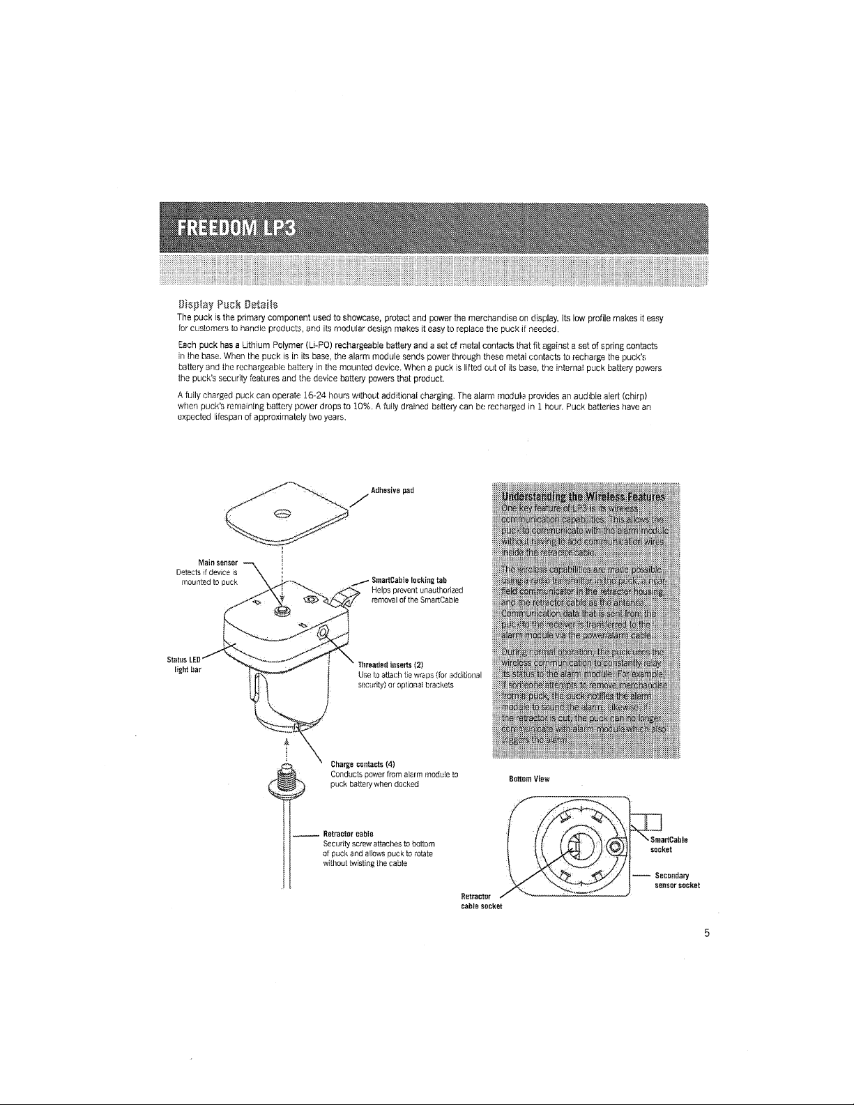
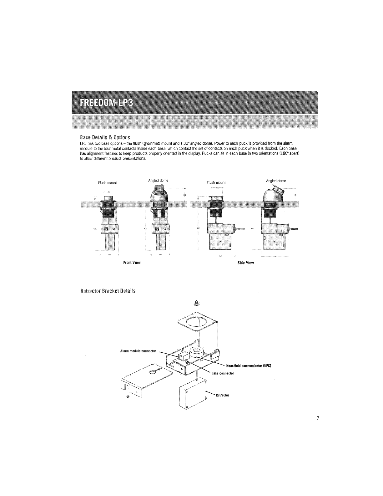
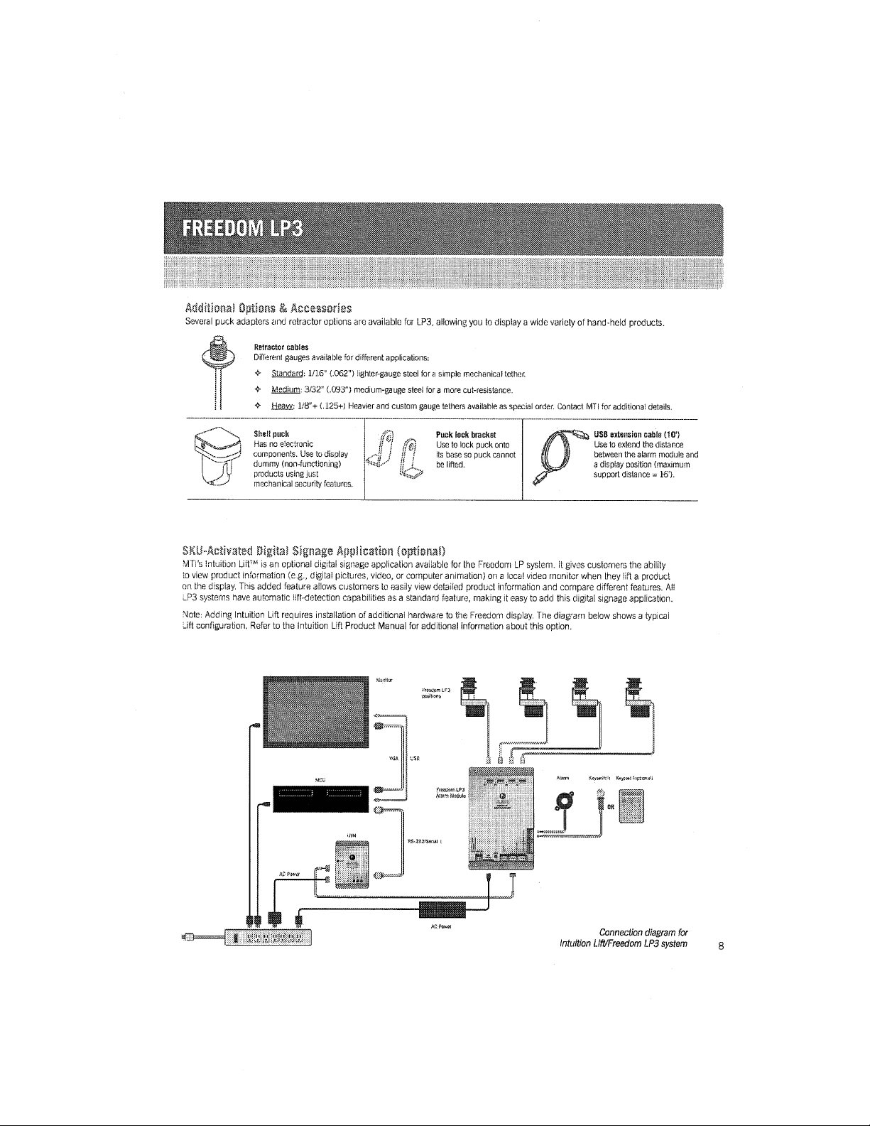
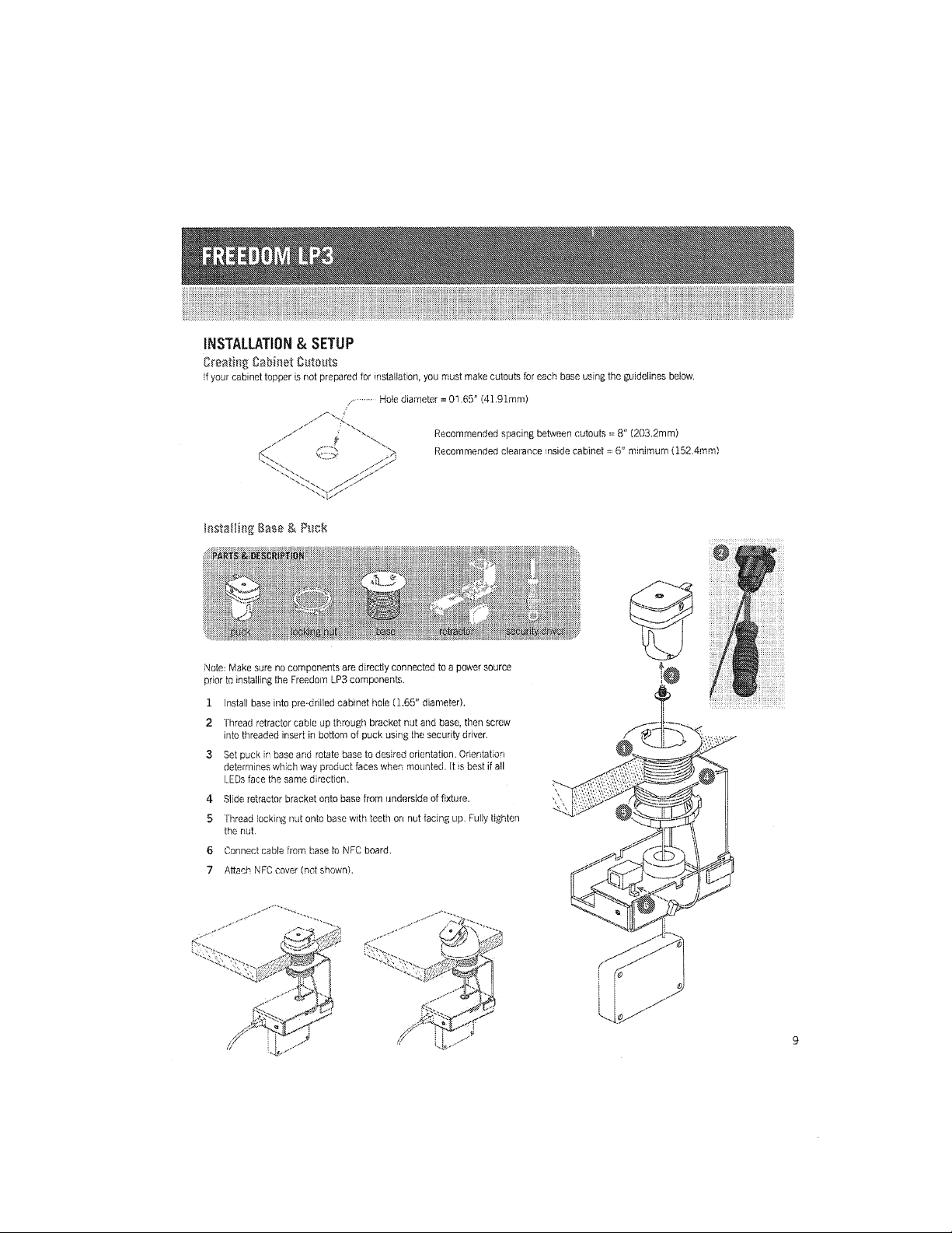
FREEDOM LP3 PRODUCT MANUAL

W3
T
M
FREEWM
PRODUCER"
MANUAL
.—00
Rev
A
:3!”
MT!
PIN
063-08
Ralaase
Date:
March
2010

CONTENTS
Overview
.....................................................
installation
3:
Setup
....................................
Operation
...................
Maintenance
...........................
Troubleshooting
..................
Features
&
Benefits.
System
at
a
Glance.
Display
Puck
Details
.......................................
Alarm
Module
Details
..................................
Base
Details
8:
Options
.
Retractor
Bracket
Details
.
Additional
Options
8:
Accessories
..
SKU-Activated
Digital
Signage
Application
(optionallu
Creating
Cabinet
Cutout
Installing
Base
84
Puck
...........
Con
nesting
System
Com
ponents......
installing
the
Battery
Backup
System
(optional)
.........................
installing
the
Power
Loss
Alarrn
Module
(optional)
...................
Configuring
the
Power
Boosters.....
Testing
the
System
.
.......
Mounting
Products
...............
Using
the
Puck
Lock
(optional)
.....
Removing
Products
...............
Arming
the
Display
Disarrning
the
Display
......
'Learn’
&
‘Auto
Learn‘
Functions.
LED
indicators,
Alarms
&
Alerts.
Solving
Alarm
Conditions
Performing
Routine
Maintenance
..................................
Limited
Warranty
..............................................

DVERVEW
Welcome
to
Freedom”
LPB
——
an
updated
version
of
MTI’S
exclusive
merchandising
system
for
small,
handheld
electronic
devrces.
This
advanced
system
allows
you
to
power,
SEECUH.
and
(
splay
merchandise
so
shoppers
can
demo
3
live,
fully
powered
device.
LP3
is
specifically
designed
for
low-profile,
low—power
handheld
consumer
electronic
devices,
such
as
mobile
phones,
MP3
players,
and
F‘DA’si
rostrum
&
§3CEzd§{\
3
offers
erai
i-iduqtiyleading
(ii
:1
ieatures
including
Wireless;
con'unninlcation
communes,
a
robust
non-powered
-th
r,
large
LED
light
bar,
and
extra-strong
adhesive
mounting
pad,
Taker:
together,
these
features
offer
better
reliability:
easier
operation,
and
the
highest
product
security
in
the
industry.
Universal
power
connector
Alarm
module
provides
DC
power
to
puck
when
puck
is
in
its
base;
Sma
rtCablem
then
delivers
correct
power
to
charge
device
batteries
Main
security
sensor
witch
triggers
alarm
if
product
is
removed
from
puck
High-band
adhesive
pad
Secures
product:
to
puck
\
x“
two
(I)
Secondary
security
sensor
"N
A
(optional-nor
sliuwnl
Provides
additional
protection
to
mod
‘:
r
or
accesso
'
s‘
such
as
a
battery
pack
(i
ameraa
.'
_‘
LED
light
bar
with
180“
View
angle
//P‘E
LED
shows
it
posit
n
is
armed
and
flashes
when
puck
is
In
state
of
alarm
Alarmed
ratractnr
cable
'
cable
security;
Retractable
display
punk
1
K
up
and
ntrol
messages
to
alarm
module
Powered
Base
Alarm
module
provides
power
.relazl
cortisol"
in
tiase,
which
hinge
e
puck
battery
.
battery
when
puck
is;
donned
Alignment
i-ealur
\"
keep
proddizls
properly
oriented
in
the
display.
Pucks
can
have
two
orientations
180°
apart.
Retractor
tracker
with
wireless
receiver
ti
eys
messages
"i
module
via
the
power/alarm
cable
46..
Am
kink
retractnr
linings
Allows
puck
to
swivel
360’
without
twisting
the
cabie,
extending
retractor
lifespan
Z9
reducing,
total
ownership
costs
Central
powerlalarm
module
lr-ot-zhrmnl
Provides
power
and
alarm
functions
for
all
products
on
display,
A
central
alarm
sounds
it
someone
attempts
to
remove
a
product
or
cut
the
retractor
cable.

Puck
Base
Mrweable
{mt
used
10
mourn
pmduct:
Plastic
hm;
ng
allar:hes
to
display
cabinet:
contains
a
wirezl
transmitter
to
has
sp
rm
alignment
features
to
orient
communicate
with
.
alarm
mudule
product
towards
from
of
d‘lSplay
Retractur
bracket
Has
receiver
to
receive
wlm‘
messages
from
puck
Retracrur
cable
Provides
rrrechanlcal
security
to
producl.
and
serves
as
arrlenna
for
wireless
transmitter
Alarm
suunder
External
alarm
(12Vdc
alarm
séren)
trlggered
if
a
product
ls
removed
from
puck
Gr
puck
ls
removed
frnm
display
Keyswitnh
Dl’
keypad
F
Tums
alarm
funcllons
on
and
elf;
also
used
to
perfcrm
the
'learn‘
functlon
Power/alarm
cabla
rrwldes
power
to
each
base/puck;
c0
nveys
belwrn
wireless
r
r&
alarm
module
w.
0R
il
ll
E
Alarm
module
Central
canteection
point
thel
pmvldes
power
and
alarm
funclluns
(see
page
6
for
alarm
medulla
details)
Power
supply
Provides
system
power
to
the
alarm
module
and
connected
devices

{Etotttas
t
task
Setottt‘t
The
puck
is
the
primary
component
used
to
showcase,
protect
and
power
the
merchandise
on
display.
Its low
profile
makes
it
easy
for
‘usttrners
to
handle
products,
and
its
rnod
Lilar
design
makes
it
easy
to
replace
the
puck
it
needed.
Each
puck
has
a
Lithium
Polymer
(Li—PO)
rechargeable
battery
and
a
set
of
metal
contacts
that
fit
against
a
set
of
spring
contacts
in
the
base,
When
the
puck
is
in
its
base,
the
alarm
modulo
sends
power
through
these
metai
czoi'itacts
to
recharge
the
truck’s;
battery
and
the
rechargeable
batteiy
in
the
mounted
device,
When
a
puck
is
litted
out
of
its
base.
the
internai
puck
battery
powers
the
puck's
security
features
and
the
device
battery
powers
that
product,
A
fully
charged
puck
can
operate:
16-24
hours
Without
addttional
charging
The
alarm
module
provides
an
audzbie
alert
(chirp)
when
puck’s
remaining
battery
power
drops
to
10%.
A
tuily
drained
battery
can
be
recharged
in
1
hour.
Puck
batteries
have an
expected
triespah
of
approximately
two
years.
Adhesiva
pad
Main
sensor
Detects
:I‘
device
is
mounted
to
puck
_/
Smartflabie
locking
tab
Helps
prevent
unauthorized
removal
of
the
SmartCable
Status
LED
light
bar
Iliraadext
insens
(2)
Use
to
attach
tie
wraps
(for
additional
,
1y)
ornpiionel.
i
Charge
mutant:
(4)
Conducts
power
from
alarm
module
to
”gift
puck
battery
when
docked
Bottom
View
W...
Retramor
came
!
l
i
t
Security
screw
attaches
to
bottom
SmartCahle
!
£5
l
s
i
at
puck
and
allows
puck
to
rotate
SODkEt
without
twisting
the
cable
----
Securidaw
sensor
socket
Retractur
cable
socket

Rig-wot
Nomi»
3mm
The
alarm
module
is
the
central
hub
oi
the
Freedom
LP
system.
Each
module
oral/toes
power
and
alarm
functions
for
Lip
to
eight
positions
and
you
can
connect
up
to
eight
modules
together
in
a
chain
to
share
a
common
alarm
and
Keyswttch.
This
module
is
not
compatible
with
earlier
LF‘
1.0
or
2.0
components.
The
alarm
module
is
powered
using
a
single
E‘RVdc
power
supply.
During
normal
operation,
the
module
supplies
SOVdc
(SEQ/dc
with
booster)
ol
power,
up
to
lOOOmA
to
each
position
via
a
USB
cable.
A
productspecil‘rc
Srnar’tCabie
delivers
the
correct
voltage
to
e
product
when
the
puck
Sits
in
its.
base.
The
alarm
module
has
an
optional
battery
‘iacimp
system
to
provioe
power
it
here
is
an
interruption
to
tno
main
power
supply,
allowing
the
module
to
continue
to
protect
the
products.
This
rechargeabie
battery
only
provrdes
power
to
keep
the
system
armed,
it
d
not
provide
any
power
to
operate
the
products.
Once
main
power
is
restored,
the
system
automatically
recharges
this
battery
so.
i
early
for
the
next
power
outage.
Position
jacks
(1-8)
Connects
to
each
retraotor;
ooveys
power
&
alarm
Signals
between
alarm
module
&
each
product
oosrtion
Main
alarm
&
keyswltoh
connectors
Connects
to
tocal
alarm
sounder
8.
keyswltch
Aux
alarm
84
keyswitch
connectors
Use
to
connect
other
alarm
modulus
il'l
a
daisy
chain,
allowing
them
to
share
a
remote
alarm
&
keyswrtcri
Power
booster
dip
switch
Use
to
bmst
power
to
positions
'7
&
‘loptionall
Aux
power
Use
to
connect
a
Power
Loss
Alarm
(optional)
l
L.
UtM
connectors
Use
to
add
optional
intuition
Lir‘t
digital
signage
application
Main
power
input
Provides;
mwer
to
alarm
rrior‘luisa
Battery
power
input
Optional
battery
pack
provides
Power
tan
temporary
power
to
alarm
module
Endicates
when
main
if
main
system
power
is
dasruoted
system
power
is
en

$33?
$3.
aim
a:
fimigns
LP3
has
two
base
options
—the
flush
(grommet)
mount
and
a
30"
angied
dome.
Power
to
each
puck
is
provided
from
the
alarm
module
in
this»
four
metal
contacts
inside
each
base,
which
contact
the
set
of
contacts
on
each
puck
when
it
is
docked.
Each
base
has
alignment
features
to
keep
products
properly
oriented
in
the
display.
Pucks
can
sit
in
each
base
in
two
orientations
(180“
apart)
to
3|ti
different
produci
presentations.
Angled
dome
Angled
come
Flush
mount
Flush
mount
Frunt
View
Side
View
2’?
£15
'1}!
5),;
:1"?
9k
133
mg
23::
"'4
Xv
(”a
7/
('22
N4!
4%
%
E.
73‘
Alarm
mudula
cunmmnr
Near-field
cammunlcaior
(NEE)
Basl
connscinr
Rmramnr

nooitionei
figit'éatiis
&
iéooefissiées
Several
puck
adapters
and
retractor
options
are
available
ior
LPS,
allowing
you
to
display
a
wide
variety
of
hand-held
products.
Ratrac’tor
cabies
Different
gauges;
available
ior
different
applications:
«5
Standard:
1/15“
(.062")
tighteregauge
sttzei
fora
simple
mechanical
tether.
¢
Medium:
3/32“
(093“)
medium-gauge
steei
for
a
more
cut-resistance.
9
Heaw:
1/‘8"+
(.t25+i
Heavier
and
custom
gauge
tethers
available
a
so
ntaci
Mil
for
additional
details.
<v-"'\\
Shell
puck
Puck
luck
bracket
Q
USB
extension
cable
(10')
if
vyax}:
H
m
electronic
Use
to
lock
puck
onto
Use
to
extend
the
distance
its
base
so
puck
cannot
be
titted.
between
the
alarm
module
and
a
display
oosition
(maximum
support
distance
2
15‘).
"[
dummy
(non-functioning)
J3
products
using
lust
\[Q—J—‘fi
components.
Use
to
display
11/
mechanical
security
features.
Mxviiuwimo
was
Signogo
itgsotimiion
iaieitioiiait
:‘il'ii’s
intuition
L
an
optional
tal
signage
application
av
bio
for
the
Freedom
LP
system.
it
gives
customers
the
ability
to
View
product
motion
(reg,
dig
ai
pictures,
video,
or
computerarximat’ion)
on
a
local
video
monitor
when
they
lift
a
product
on
the
display.
This
added
feature
allows
custoi‘ners
to
easily
View
deiaiied
product
in
formation
and
compare
different
features.
All
systems
have
automatic
iiiioisitectio
e.
pabiiities
as
a
stai'idard
feature,
making
it
easy
to
add
this
digital
signage
application.
3...»
Note:
Adding
intuition
Lift
requires
installation
ofadditionai
hardware
to
line
Freedom
display.
The
diagram
below
shows
a
typical
Lift
configuration.
Refer
to
the
intuition
Lift
Product
Manual
for
additional
information
about
this
option.
i'mwm
tr:
Mimi‘s
Kuvwiitfii
Kieyi-wl'nptmuii
want-mm
HRZBZISMM
i
AL:
Pam
Connection
diagram
for
intuition
Lift/Freedom
LPE
system
8

titer-sting;
Qtteiitet
{Meets
it
your
cabinet
topper
is
not
prepared
for
installation,
you
must
make
cutouts
for
each
base
u5irig
lhe
guidelines
below.
Nate:
Make
sure
no
components
are
directly
connected
to
a
power
source
prior
to
installing
the
Freedom
t.P3
components.
1
2
------
Hole
diameter:
01.65"
(4191mm)
‘\\
Recommended
spacing
betv
,isin
cutouts
‘3”
(2032mm)
t)
Recommended
clearance
inside
cabinet
2:
6"
minimum
(152.4mm)
(.xfi/
,
,z
/
install
base
into
prevclrilled
cabinet
hole
(1.65"
diameter).
Thread
relraclor
cable
up
through
bracket
nut
and
base,
then
screw
into
threaded
insert
in
bottom
of
puck
using
the
security
driver.
Set
puck
in
base
and
rotate
base
to
desired
orientation.
Orientation
determines.
which
way
product
taces
when
mounted.
it
is.
best
it
all
LEDs
lace
the
same
directicn.
Slide
retractnr
bracket
unto
base
from
underside
of
fixture.
thread
kicking
nut
ante
base
with
teeth
on
nut
lacing
up.
Fully
tighten
the
nut.
Connectceble
tram
base
to
NFC
board.
Attach
NFC
cover
(net
shown).
LO

u‘§§§§3§3$‘§£§§§§
$§S€$m
$ot€§gt§i§t¥t§t§
imnmta
i
Obsen/e
wire
polarity
when
can
netting
[hr
larm
and
keyswitcti.
The
red
Wires
must
connect
to
the
poalttvo
[+3
termlna
9
black
wires
must
connect
to
the
negative
(—i
terminals.
1
Use
four
screws
to
secure
alarm
modulets)
to
the
display
cabinet
or
other
mounting
location.
2
install
an
alarm
sounder;
then
connect
wires
from
alarm
to
the
ALARM
connectors
on
the
alarm
module,
Note:
install
alarm
sounder
outside
the
cabinet
whore
it
can
be
heard,
but
not
easily
seen
by
customers.
3
Install
koyswitch
or
Keypad;
then
connect
wires
to
the
KEY
connectors
on
the
alarm
modulo.
Connect
a
power/alarm
cable
between
each
retractor
and
the
Position
lacks
on
the
module.
immfianié
Connect
cables
in
sequence,
starting
With
pc-Sitlon
1.
For
example,
ifyou
are
using
four
display
positions,
connect
them
to
positions;
1,
2, 3,
4
on
the
alarm
module.
5
It
the
system
requires
more
than
one
alarm
module,
you
must
daisy
chain
the
modules
to
share
the
central
alarm
and
keyswltch.
To
daisy-chain
the
modules,
connect
a
4—cond
uctor
cable
(22awgi
between
the
KEY/ALARM
terminal
connections,
using
the
same
color
coding
(red,
black,
white
and
green)
on
each
module.
You
only
need
to
connect
one
of
the
moduies
to
the
Mini
and
Keysthch.
Plug
the
external
power
sup-ply
into
the
power
input
jack.
Connect
the
power
supply
to
a
suitable
AC
power
source
(pro
rabéy
a
power
strip
in
the
cabinet).

\\\\\\\\\
toststting
the
hurt
§§§§$§Sit§§
Systerr
{egsésssit
The
battery
backup
system
provides
temporary
power
to
keep
the
system
armed
when
the
main
power
supply
is
off.
This
is
useful
if
there
is
an
unexpected
interruption
to
the
main
power
supply
or
lithe
main
supply
is
turned
criiat
night
as
part
of
the
store’s
operation
The
battery
backup
system
does
not
sound
an
alarm
if
power
is
disrupted;
that
requires
installation
oithe
Power
Loss
Alarm
t‘vloduie
(see.
section
below).
reporters“
if
the
display
does
not
have
a
battery
backup
system
or
a
Power
Loss
Alarm
Modutizi
(described
below),
it
is
possible
tor
someone
to
disable
the
main
alarm
by
unplugging
or
cutting
the
main
system
power,
thus
making
merchandise
vulnerable
to
theft.
To
instali
the
battery
backup
system:
Turn
off
power
to
the
“
play.
1
2
install
battery
module
in
display
cabinet
where
terminals
will
not
be
shorted.
3
Plug
battery
cable‘s
73-pin
header
into
BATTERY
connector
on
alarm
module.
4
Connect
fast-on
terminals
to
battery
terminals
{red
wire
to
red
(+)
terminal;
black
wrre
to
black
(—l
termrnall.
Attach
a
multi—directional
tie
holder
to
module
to
create
strain
relief
tor
cable
connections.
battery
module
'
5
Connect
fork
terminals
to
battery
charger
screw
terminals
(red
wire
to
+
terminal;
black
wire
to
~
terminal).
6
Plug
battery
charger
into
power
str=p
and
restore
main
system
power,
Verify
that
one
of
the
charger
LEDS
Is
lit,
The
red
LED
lights
it
system
is
charging;
the
green
LED
lights
ii
system
is
charged.
Mitts
Power
i
has
Alarm
Module
(PLAM)
is
an
optional
security
feature
tor
the
LPB
<“stem,
This
module
automatically
triggers
the
alarm
ir‘
som
e
disrupts
the
system
power
anywhere
along
that
cult,
and
it
has
a
rechargeable
battery
that
powers
the
alarm
until
the
atar
condition
is
resolved
and
the
keyswitch
is
cycled,
nepotism
it
the
display
does
not
have
a
power
loss
module
or
a
battery
backup
system
(described
above),
someone
can
disable
the
main
alarm
by
unplugging
or
cutting
the
main
system
power,
thus
maliing
merchandise
vulnerable
to
theft.
To
install
the
RAM:
1
Set
system
koyswitoh
to
DISABLE
ALARM
and
turn
oil
power
to
the
display.
2
Remove
back
cover
oi
the
PLAM
and
install
the
rechargeable
battery
iprovidoo‘).
3
Mount
modLil'=
in
a
secur'=
location.
.
-.
.
-
.
“
3
”33333333
4
Connect
a
4»piri
keyswitch/alarm
cable
between
the
KEY/ALARM
input
on
the
power
loss
module
and
the
KEY/AtARti/i
connector
on
the
system‘s
alarm
module.
5
Connect
a
2.pin
power
cable
between
the
power
input
connector
on
the
power
loss
module
and
the
AUX
POWER
output
on
the
system's
alarm
modules
6
Turn
on
power
to
the
display
and
set
Mei/switch
to
ALARM
ON.
7
Verity
that
the
PLAM‘S
power
LED
is
on
and
the
battery
is
charging
(ClrlARGE
LED
is
on).
Note:
Refer
to
the
Freedom
Power
Loss
Alarm
Module
Product
Manual
(063-0588-00)
for
additional
details.

‘tmsté
;§§§‘§E‘§g
m
Fax-wt
SNWQ
ézsmiss‘zssfii
You
can
boost
power
to
two
product
posiitcms
i
.7
&
8)
if
you
are
mounting
devices
that
have
higher
pawer
requirements.
vtng
a
position
boosted
when
it,
does
not
require
a
booster
wiil
not
negativeiy
impact
the
devtce
or
the
pettermance
of
the
device.
H’
Ensum
that
SKUs/posttiai'is
requiring
the
Power
Booster
are
merchandise-d
on
aiarm
posttions
7
and
8.
1
caliy
boast
positions
7
and
S
2
Depress
dip
switch
#6.
Depre"
stiriulianeotisly.
g
the
(1:9
switch
into
tne
'oni
{mitten
w=ii
automsa
'
PDSR‘IGNS
REQUMRG
POWER
BBOST‘
DIPSWRCHL‘;
"
VGSFHDN
6
24,—»:
"re-w.
,0.
O
12

Turn
on
main
system
power.
Verify
that
Power
LED
on
alarm
moduleis)
is
on.
Cycle
keyswitch
(turn
from
DlSAB‘LE
ALARM
tc
ALARM
ON)
to
reset
system,
Verify
that
Status
LED
on
each
puck
is
flashing
twice
every
7
seconds.
This
indicates
puck
is
communicating
with
alarm
module.
l-told
down
trigger
switch
cn
top
of
puck
for
It
minute,
Verify
that
system
automatically
learns
and
arms
this
pceition
(LED
should
be
lit
solid
when
puck
is
docked and
flashing
once
even/3
seconds
when
lifted}.
Remcve
finger
from
trigger
switch.
Verify
that
puck
goes
into
an
alarm
state
(puck
LED
should
be
flashing
two
times
every
second
and
alarm
should
be
soundim).
Cycle
keyswitch.
Verify
that
alarm
sounder
goes
off
and
that
puck's
LED
is
flashing
twice
every
7
seconds
when
docked.
(Note:
alarm
may
re
:tivate
ir'
...
g
'
is
cycled
too
quickly.)
Repeat
steps
476l13r
all
positions.
Hold
down
trigger
gwitch
on
puck
and
cycle
keyswrl‘ch.
Disconnect
retractor
cable
from
puck
bottom.
Verify
that
puck
goes
into
an
alarm
state
(puck
LED
should
be
flashing
two
times
every
second
ant:
aiafrn
should
be
sounding).
Note:
Be
very
careful
not
to
éet
go
of
the
cable
as
this
coule
damage
the
ircuit
boards,
A
loose
knot
may
he
tied
in
the
_
actorcableifyou
want
to
heeptt‘e
Nb!
from
pulling
through
the
..
10
Cycle
Keys-Witch
and
reconnect
retractor
cable.
11
Repeat
steps
9-10
for
all
positions.
12
Cycle
Keyswitch
to
reset
the
system
when
finished.

trioortting
theorists
1
Set
alarrn
keyswltch
to
DlSABLE
ALARM.
2
Clean
top
of
display
puck
anti
back
of
device
with
alcohol
wipe.
Allow
both
to
dry.
Attach
VHB
pad
to
top
of
puck.
3
Plug
SmartCahle
(mini-U88
end
with
retaining
tabs)
into
hack
of
truck.
imminent?
You
must
plug
the
SmartCablo
into
the
puck
before
mounting
the
device.
if
you
skip
this
step,
you
will
need
to
remove
the
device
in
order
to
connect
the
Smai‘tCable.
4
if
device
has
removable
battery
door,
use
small
squares
of
double-sided
tape
to
secure
the
battery
door
to
the
inside
of
the
device.
Malta
sure
you
place
the
tape
to
a
flat,
mm;
mmgxatttefliflace
inside
the
battery
compartment
that
will
make
contact
with
the
battery
door
when
it
is
shot.
5
Review
the
Mounting
Recommendations
below
belore
proceeding.
Remove
backing
on
the
VHS
pad
and
attach
deVice.
Press
firmly
to
ensure
full
adhesion
ofthe
VHB
pad.
Plug
other
end
of
SmartCa
is
into
device‘s power
port.
If
your
kit
includes
a
secondary
security
sensor,
conne-c
'i
to
the
puck.
Attach
the.
sensor
head
to
the
device.
it
is
good
practice
to
always
use
a
secondary
sensor,
even
it it
is
not
included
in
the
kit.
8
Thread
one
zip
tie
through
channel
in
puch
and
wrap
around
dew/ice
Use
.
other
tie
t
cure
the
economy
sensor
head
to
the
on
for
at
least
12
hours
so
adhesive
bond
can
gain
full
strength.
9
Turn
on
(lei/ice
to
verify
it
powers
on.
Once
you
verify
power,
rcset
the
alarm
kcyswitch
to
ALARM
0N.
Verify
that
the
puck
light
bar
is
on
and
not
flashing.
Mounting
Recommendations
9
“Button’
on
top
of
puck
is
the
primary
sensor
trigger.
it
must
be
depressed
fully
to
ensure
product
security
and
avoid
false
alarms.
(r
it
possible,
attach
puck
over
both
the
body
and
removable
=cattery
door.
Be
sure
to
attach
the
puck
to
as
much
of
the
body
as
possible.
<>
Offset
the
puck
slightiyto
one
side
in
order
to
help
hide
the
secondary
sensor.
¢
A
secondary
sensor
is
only
required
it
included
in
kit.
¢
Attach
secondary
sensor
to
a
flail,
non—removable,
nun—mov—
ing
surface
on
device
where
it
Will
not
interfere
with
device's
operations.
0
it
is
best
to
mount
the
secondary
sensor
to
track.
of
device.
if
sensor
will
not
fit
on
back.
or
it
the
entire
back
is
removable,
place
sensor
on
face
of
device.
The
mounting
area
should
be
large
enough
to
prevent
the
sensor
from
rocklng.
9.
llow
for
motion
if
device
flips
open
or
slides.
.0
Try
not
to
cover
camera
lenses
With
the
puck
or
secondary
sensor.
The
flash
can
be
covered
if
necessary.
\\
\
\
‘
‘
.EQSSIBLE
DEVlUES,
_.
Actual
devices,
cables;
sensors,
may
vary.
UFFSET
BUCK
SlnglNG
PHONES
FLIP
"roves
, .
lbrrraa
ssconr/anr
Altair
'0!
(vi!
movement
Allow
'orv
1‘in
increment
sensor
harm
grin:

tisisg
first
first:
magi
{pptémsai}
You
can
secure
a
puck
to
its
base
usmg
the
puck
lock
bracket
This
provides
additional
product
security
by
preventing
access
to
the
reti'actor
cable
To
use
this
option:
1
Lift
puck
and
insert
puck
luck
brackets
into
the
base.
2
Return
puck
to
base;
then
insert
two
security
screws
through
bracket
into
threaded
inserts
on
puck.
wwiiig
Pi;
Ems
1
Set
keyswltch
to
DiSABLE
ALARM.
2
Remnve
Sman‘Cahle,
zip
ties.
and
secondary
sensor
(if
present)
from
puck.
3
Use
puck
removal
tool
to
twist
the
puck
hack
and
forth
until
the
pad
separates.
The
pad
should
split
in
half,
leaving
adhesive
tape
on
both
product
and
puck
4
Reprieve
adhesive
from
product
and
puck
usmg
your
thumb
to
roll
tape
off
the
surface
Use
rubbing
alcohoi
to
clean
top
pi
puck
and
back
of
product.
6
Turn
keyswitch
to
ALARM
ON
when
finished
to
rearm
system
iii}?
Thfi
adhesive
pad
is
very
strong".
it
you
have
ail"
ulty
twisting
the
uni
.
use
a
flat-A
Gad
screw
or
other
tool
ti)
first
score
the:
(
'iter
at
til-3
part
on all
lciur
sides.

UPERATiON
in;
“
oi:
Discharge
yourself
or’
any
static
electricity
buitdup
before
touching
any
sensitive
electronic
components
in
the
display.
You
can
do
this
by
placing
your
hand
on
any
adjacent
metal
oountortop
or
shelf
unit.
firming
tho
oisotoy
1
Turn
on
power
to
the
system.
2
Turn
on
aii
mounted
products.
3
Turn
keyswitoh
from
DISABLE
ALARM
to
ALARM
ON.
4
Verifyall
pucks
with
mounted
products
have
a
solid
LED.
System
is
now
armed
and
ready
for
use.
tfiésorotiz‘tg
the
oiaoéoy
To
disarm
the
display.
turn
the
keyswrtoh
to
DtSABLE
ALARM
The
mounted
devices
wiii
continue
to
operate
usrng
their
internal
battery
power
a1d
the
LEDs
will
remain
on,
but
no
alarms
will
trigger.
Law
o
Mo
torso?
wows
The
alarm
feature
works
by
having
the
system
initially
perform
a
‘learn'
function
to
check
the
exrsting
product/puck
configuration.
It
then
resets
the
alarm
module
to
treat
this
existing
configuration
as
'normai‘
so
that
it
can
monitor
changes
to
the
security
sensors.
tor
oxampio,
it
there
is
not
a
product
mounted
on
a
puck.
the
missing
product
would
normally
trigger
an
alarm
because
of
the
open
sensor.
With
the
learn
function,
however,
the
Eli
stem
now
thinks
the
missing
product
is
normal
so
no
alarm
sounds
when
it
detects
the
open
sensor.
The
learn
iunotion
is
poriormed
whenever
you
turn
the
koyswitch
from
DISABLE
ALARM
to
ALARM
ON,
and
when
the
main
system
power
is
recycled
or
restored.
The
system
atso
automatically
performs
this
learn
function
when
a
new
product
or
sensor
is
added
to
the
display,
This
actitnates
and
arms
the
new
sensor
without
having
to
relearn
the
new
configuration
using
the
keyswitch.
This
‘auto
learn'
operates
as
ioiiows:
Q
If
you
add
a
secondary
sensor
to
a
product
on
a
learned
puck‘
the
sensor’s
LED
will
flash
every
2
seconds.
if
the
sensor
ion-rams;
closed
for
60
seconds
(continuous).
it
will
be
automatically
learned
and
its.
LED
will
turn
solid.
<>
if
a
product
is
mounted
to
an
unlearned
puck
and
one
or
more
of
its
sensors
are
closed
for
60
continuous
seconds.
the
puck
will
be
automatically
learned
and
its
LEDis)
wiil
turn
solid.

LED
off
Solid
LED
Double
flash
every
1
second
with
steady
alarm
siren
No
power
Puck
is
armed
(battery
drained)
&
aclive
Security
alarm
Single
flash
every
lED
fo
Double
flash
every
3
55mm:
(no
device
mountedi
7
seconds
Battery
backup
mode;
puck
is
armed
LED
nff
No
power
{battery
drained)
LED
UK
will!
sleaily
alarm
siren
luuck
oul
of
new)
Battery
backup
mode
0!
no
Dower
Single
flash
every
3
seem-ids
Puck
is
armed
&
:l:i\re
LED
off
(no
device
rnourz
:'
Fuck
left
out
or
base
more
than
4
hours
causing
5
Battery
backup
mode
or
communicatlm
tnturn
off
i
no
power
(battery
drained)
*Keyswrtch
set
to
ALARM
ON
(no
device
mounted)
Puck'
~orrirnuriir:aling
bu
until'armerl
Single
flash
every
l
second
with
steady
alarm
siren
Security
alarm
Duuhle
flash
every
5
seconds
in:
device
mounted)
Puck
is
communicating
but
is
not
armed
The
alarm
module
uses
two
types
0f
audible
signals
—
an
alarm
siren
and
an
alert
Chirp
{snort
been).
The
siren
sounds
when
there
an
issue
with
I:
2
product
security,
h
as
th
urr
l‘ncrlzed
removal
of
a
prriduct.
The
alarm
module
emits
an
alert
chirp
if
there
is
a
system
maintenance
issue.
Steady
alarm
siren
Security
alarm
caused
by:
¢
Product
renmvecl
from
an
armed
puck
¢
Active
puck
taken
from
the
display,
lusrng
communication
with
alarm
module
#-
Relraclrir
cable
cut
¢.
Secnndary
security
sensor
removed
or
unplugged
¢
Product
mounted
incorrectly
+
Faulty
puck
4}
Fuck
left
out
at
base
more
than
4
hours
Alarm
siren
cycles
5
secnnris
an
and
55%
then
5
seconds
all;
puck
LED
flashes
every
3
seconds.
Cycling
keyswiich
will
not
alleviate
symptom.
Power
short
between
the
alarm
module
and
charge
contacts.
System
removes
power
to
the
affected
position.
Alarm
Ian/eff
sequence
continues
until
problem
is
solved.
(Note:
This
alarm
will
not
sound
it
keyswlich
is
set
to
DlSABLE
ALARM}
Single
chirp
every
minute
Puck
left
out
oi
base
for
more
than
2
no:
te.
Dcuhla
chirp
and
flashing
LED
after
4
seconds
when
puck
is
returned
to
base
or
when
keyswilch
‘learn'
event
is
periorrnerl.
Cycling
keyswiich
will
not
alleviate
symptum.
Short
lecilll
in
SmarlCat)le
nrcle
'.e.
Syslem
turns
off
pnwur
in
device
until
issue
is
resolved
Puck
security
remains
runcliunal.
Triple
chirp
every
minute
Punk
battery
is
law
«20%
ballenr
life).
Ten
chirps
every
30
minutes
System
is;
operating
in
ballery
backup
mode.
Chiming
will
stop
once
main
power
is
r‘eslored.
17

ts
‘~
\\
\\\\\
:
transitions
1
Check
L
on
alt
active
trucks
before
turning'
the
key-switch
to
DISABLE
ALARM.
The
alarming
position
will
have
a
flashing
LED
unless
th
retractor
cable
was
cut
and
pucl-r.
is
missing.
2
Once
you
have
identified
the
alarming
position,
turn
the
keyswitch
to
DISABLE
ALARM
to
silence
the
alarm
3
identity
and
fix
the
alarming
position
usrng
the
list
at
alarming
conditions
on
the
previous
page
as
a
guide.
if
the
retractor
cabie
was
{tutor
damaged,
disconnect
the
retractorand
replace
itwrth
a
new
one.
4
Turn
keyswi‘rch
back
to
ALARM
UN
to
rearm
the
system
T:
puck
LED
should
be
solid
red
indicating
it
:5.
again
active
and
armed,
Th
,ystem
prowess
temporan/
power
to
keep
the
system
armed
when
the
main
power
supply
is
0%
ll
'
.
the
main
power
supply
or
it
the
main
supply
is
turned
tilt
at
night
as
part
0!
the
store
a
or)
otion.
When
the
main
power
goes
oit,
the
system
automatically
5
into
battery
backup
mode
and
the
alarm
sounder
chirps
tent
*.
The
system
will
continue
to
chirp
ten
times
every
30
mini“
,L
ritil
the
main
power
is
restored.
When
operating
in
battery
backup
mode,
the
i.EDs
on
peeks
with
mounted
products
tlash
once
every
3
seconds.
This
indicates
products
are
still
secure,
but
system
is
operating
in
battery
mode.
The
backup
battery
can
only
provide
power
for
a
limited
time,
up
to
18
hours
on
a
fully
populated
alarm
module.
Once
power
ts
restored,
the
system
returns;
to
the
normal
operation
mode.
The
system
then
automatically
recharges
the
battery
as
needed.
tmportasttt
The
battery
backup
mode
only
provides
power
to
keep
the
system
armed
it
does
not
provide
any
power
to
operate
or
recharge
the
products.
The
alarm
module
will
also
not
learn
any
new
pucks
when
operating
in
this
mode,
MAINTENANCE
trttperisarsti
Discharge
yourself
or“
any
static
electricity
buiidup
before
touching
any
sensitive
electronic
components
in
the
display.
You
can
do
this
by
placing,
your
hand
on
any
adjacent
metal
countertop
or
sheil‘
unit.
“3-
<«
:w.
'-
sa‘.
,
re:
sweat»;
Retains
maintenance
‘:
ely
check
the
retractdr
cables
to
ens-tire
they
are
not
damaged
or
worn.
Reataaing
the
nest
satiety
n
\v\
it
you
‘
=
the
puck
is
no
longer
cemmur‘rrcatingwith
the
alarm
module,
the
internal
puck
battery
may
need
to
be
replaced.
Please
contact
M‘l‘l
Customer
Service
for
replacement
instructions
maternity:
System
Sempoeertts
The
system's
modular
design
makes
it
easy
replace
system
components
it
they
are
damaged
or
test.
To
replace
components:
Turn
lteyswitch
to
DISABLE
ALARM,
and
then
turn
oft
the
system
power.
Disconnect
any
cables
to
the
compon
t.
Remove
the
component
and
replace
as
necessary.
1
2
3
4
Reattaeh
the
cables
as
required.
5
Turn
on
the
system
power.
6
Turn
keyswrtch
to
ALARM
ON.
Note:
Reterto
the
'lnstallatiori
&
Setup'
section
i
trootions
on
installing
and
connecting
the
components,

TRGUBLESHGGTENG
All
MTI
products
are
designed
and
manuiactured
to
provide
consistent,
trouble—tree
service.
tithe
display
has
a
problem,
refer
to
the
troubleshooting
tabie
beiow.
if
the
problem
persists,
contact
MTl
Customer
Service
at
16004266844
[toll-free)
or
503
cservicetstmti-interact:ve.i::orri.
._)s
are
on
Dev
3
battery
is
notcnarglng
or
only
"
'ntermittently
.
intermittent
false
alarms
LED
is
not
solid
even
though
product
is
present
LED
efiwith
steady
atarm
siren
when
puck
is
out
of
base
658
5500
(international),
from
8AM
-
5PM
Pacific
Time,
Monday
through
Friday.
Please
send
faxes
to
503.648.7500
or
e—mail
A
power
Jgis
iripluggedtromthevall
outtet
or
power
strip
(if
used}
is
turned
off
Ensure
AC
power
is
securely
plugged
into
the
wall
outlet
and
power
strip
is
on
Power
suppiy
is
not
connected
to
the
alarm
Piug
power
supply
into
the
alarm
modu‘e
module
Wrong1
SmartCable
was
used
or
is
not
Connect
the
correct
SmartCable
connected
Loose
cable
connections
between
alarm
Check
cable
connections
between
alarm
mod
ule
and
retractor
module
anc-
retractor
Damaged
base
contacts
or
connections
Replace
damaged
parts
Puck
is
not
correctly
seated
in
its
base
Check
contacts
on
puck
and
base
to
ensure
clean
connection
when
puck
i
eating
in
base
Pro-3‘
bet
is
not
securely
mounted
to
puck,
ailowing
alarm
sensor
to
lift
terriount
product
on
puck
with
new
adhesive
pao‘,
Ensure
that
the
alarm
sensor
is
fully
depressed.
Secure
product
with
tie
wraps
for
a
minimum
of
24
hours,
Damaged
retractor
cable
or
puck
'tepiace
damaged
parts
Loose
cable
between
alarm
module
and
NFC,
or
loose
connection
between
retractor
and
puck.
or
loose
cabie
between
base
and
NFC
Check
all
cable
connections;
secu
=-
with
tie
wrap
it
needed
to
provide
strain
reiiet
Position
was
in
alarm
state
when
‘iearn'
function
was
performed
‘urn
keyswitch
to
DiSABLE
ALARM
and
resolve
alarm
issue;
then
return
switch
to
ALARM
0N
Position
has
damaged
puck
tepiace
puck
Product
irriiziroperiy
mounted
Qemount
product
on
puck
Ensure
that
alarm
sensor
is
fully
depressed.
Secure
product
with
tie
wraps.
?eturn
puck
to
base;
then
recycle
keys-witch
to
silence
alarm
Puck
left
out
of
base
more
than
4
hours
causing
puck
communication
to
shut
down
Other manuals for FREEDOM LP3
1
Table of contents
Other M-TI Cell Phone Accessories manuals