M-TI Freedom Axis User manual

©2008 MTI. All Rights Reserved.
FREEDOM™AXIS™
MTI P/N 063-1155-00 Rev B
Release Date: January 2013
PRODUCT MANUAL

FREEDOM UNIVERSAL 2.0
2
FREEDOM AXIS
CONTENTS
Overview���������������������������������������������������������������������������������������������������������3
System Components & Features������������������������������������������������������������������������������������3
Puck & Mounting Saddle Details�����������������������������������������������������������������������������������4
Base Options & Dimensions������������������������������������������������������������������������������������������5
Installation & Setup�����������������������������������������������������������������������������������������5
Installing the Lock�������������������������������������������������������������������������������������������������������5
Installing System Components ��������������������������������������������������������������������������������������6
Mounting Products ������������������������������������������������������������������������������������������������������8
Removing Device from Saddle ��������������������������������������������������������������������������������������9
Removing Base from Fixture���������������������������������������������������������������������������������������10
Operation ����������������������������������������������������������������������������������������������������� 11
Basic Operation & Use ����������������������������������������������������������������������������������������������� 11
Using the Quick-Release Feature �������������������������������������������������������������������������������� 11
Maintenance �������������������������������������������������������������������������������������������������12
Troubleshooting�������������������������������������������������������������������������������������������� 12
FCC Compliance �������������������������������������������������������������������������������������������12
Limited Warranty ������������������������������������������������������������������������������������������13

FREEDOM UNIVERSAL 2.0
3
FREEDOM AXIS
OVERVIEW
Welcome to Freedom Axis™ (Patent Pending), a rugged merchandising system from MTI specically designed for today’s rapidly
evolving tablet market. Freedom Axis is the only tabletop merchandising solution that offers mechanical security, universal power for all
tablet models (up to 21 volts), and full 360-degree spinning interaction.
Because of its robust mechanical security, Freedom Axis is the perfect solution for high-risk areas. The basic system is comprised of
an external power supply, a base with rotating puck, and a mounting saddle. The mounting saddle attaches to the tablet using a large
VHB™ adhesive pad, and this saddle is then secured to the puck using a mechanical lock and key. The external power supply provides
power to the rotating puck, which then conveys power to the tablet using an MTI SmartCable™.
Once installed, Freedom Axis allows customers to demo fully powered tablets in both portrait and landscape orientations while keeping
the devices secure. If customers want to get a better feel for the product, store employees can use the key to quickly release the saddle
and tablet from the base without having to remove the adhesive pad. When the demo is nished, simply return the tablet and saddle to
the base and once again lock it in place.
System Components & Features
Power supply (not shown)
Provides power to recharge
mounted device
Mounting saddle
Secures device to puck
SmartCable (not shown)
Delivers correct power from
puck to mounted device
Puck
Secures saddle to base &
delivers power to device via
SmartCable
Security key
Use to release device
for tetherless demos
Swivel collar
Allows full 360-degree
rotation of puck &
mounted device
Base
Secures system
to xture top
Saddle removal tools Security driver
003-0056-00
Use to install and remove
optional security brackets
Three base options
Through-hole (two versions) and surface-
mount base options allow for different display
congurations�
Optional mounting brackets
Mechanical brackets can be added to provide
enhanced product protection�
Strong mechanical security
Tablet is secured to mounting saddle using
large VHB adhesive pad� Saddle is then secured to
puck & base using a robust mechanical lock�
Universal power to 21 volts
System can charge all tablet
devices, including eReaders &
netbooks, so device is always
ready for demo use�
Quick-release feature
Locking saddle mechanism
allows store employees
to easily remove tablet,
providing customers a
personalized & tetherless
demo experience�
Plate
Handles
Full 360-degree rotation
Customers can spin the
tablet a full 360 degrees
to demo in portrait or
landscape mode� A slight
stop every 90 degrees
provides feedback to the
user & keeps the tablet
stable in the selected
orientation�

FREEDOM UNIVERSAL 2.0
4
FREEDOM AXIS
Optional Mounting Accessories
Mounting saddle
(see detailed view at right)
Opposite Side View
Installed using the
security driver Installed using the
security driver
Puck & Mounting Saddle Details
Saddle Details
Puck
SmartCable
connector
Cable security tab
Fits tightly around SmartCable to
secure cable connection
Cable security tab
Mounting
bracket slot
VHB adhesive pad
Secures device to saddle
Mounting bracket (optional)
Two brackets t around device
to provide additional mechanical
security (see details below)
Lock
Custom mounting bracket
Mechanical bracket mounts around
the tablet to provide additional product
security. Standard bracket ts most
tablet models. Custom brackets
available upon request.
Standard VHB extension wings
Provide more adhesive surface for
additional product security.
163-0220-00 (black)
163-0220-0011 (white)

FREEDOM UNIVERSAL 2.0
5
FREEDOM AXIS
Base Options & Dimensions
Freedom Axis offers three base options – a surface-mount riser, a through-hole riser, and through-hole mount. Both risers present the
mounted device at a 35-degree angle.
Installing the Lock
The diagram below shows how to install a new lock unit.
INSTALLATION & SETUP
Surface-mount riser
Attaches directly to xture
top using mounting screws
or VHB adhesive pad
Through-hole riser
Installs through xture
top (requires 1.65” hole)
Through-hole mount
Installs through xture
top (requires 1.65”
hole). Recommended
for angled xtures
(35-degree minimum and
above) or vertical wall
installations.
1� Orient new lock so detent is facing up
Incorrect (not ush)
Correct (ush)
2� Insert lock into the socket until lock
snaps in place; edge of lock should
be ush with surface of puck

FREEDOM UNIVERSAL 2.0
6
FREEDOM AXIS
Angled risers should be mounted on a
horizontal surface.
The short, through-hole mount is recommended for
angled surfaces (35 degrees up to vertical).
Recommended base spacing to accommodate most tablet
models is 12 inches on center (minimum).
Hole Diameter
1.65” (min)
1.75” (max) Underside of xture
Locking nut
Tightening tool
Install components so the mounted device(s) will be able
to fully rotate without interfering with the xture, walls, or
other positions. If the device will be powered, make sure
the SmartCable will not interfere with xture, wall, or other
positions and will rotate without interference.
Installing System Components
Before you begin: Review mounting recommendations and the installation steps below to help determine the desired mounting
location of all components..
Secure base to xture using one of the three options described below:
Option A: Locking nut (through-hole bases
only)
A. Drill hole through the xture top.
B. Insert base into hole; then rotate to
desired orientation (direction that puck and
mounted device will face).
C. Thread locking nut onto base with teeth
on nut facing up.
D. Tighten locking nut as tight as possible
using the tightening tool (base should not
spin).
1
C
D
B
A

FREEDOM UNIVERSAL 2.0
7
FREEDOM AXIS
Removing Device from Saddle
Option B: Mounting screws (surface-
mount bases)
1. Position base in the desired
mounting location and orientation
(direction that puck & mounted
device will face).
2. Route the power cable though
the channel in the bottom of
the base (cable remains on top
of mounting surface) or down
through a hole in the xture top
(cable hidden below mounting
surface).
3. Using the four mounting holes
as a guide, pre-drill pilot holes
into the mounting surface.Insert
mounting screws, being careful
not to overtighten the screws.
Option C: VHB adhesive pad (surface-mount bases)
1. Position base in the desired mounting location
and orientation (direction that puck & mounted
device will face).
2. Route the power cable though the channel in
the bottom of the base (cable remains on top
of mounting surface) or down through a hole in
the xture top (cable hidden below mounting
surface).
3. Using the four mounting holes as a guide,
pre-drill pilot holes into the mounting surface.
4. Insert mounting screws, being careful not to
overtighten the screws.
Place external power supply in a secure location,
then connect the power supply cable to the power
input cable wrapping the locking strap around the
connector.
Plug the external power supply into an AC power
source, preferably a surge-protected power strip in
the display cabinet.
2 3
C
CB
B
A
To route power cable on top:
Route power cable through
channel in underside of
base so base sits at
To hide the cable below:
Drill hole (1” min) in xture
top and route cable through
this hole
Secure with four
security screws
Channel in underside of base
Freedom Axis Base
Cable from external
power supply
Locking strap
Power supply Power strip
AC Power
Source
Power input
Cable

FREEDOM UNIVERSAL 2.0
8
FREEDOM AXIS
Mounting Products
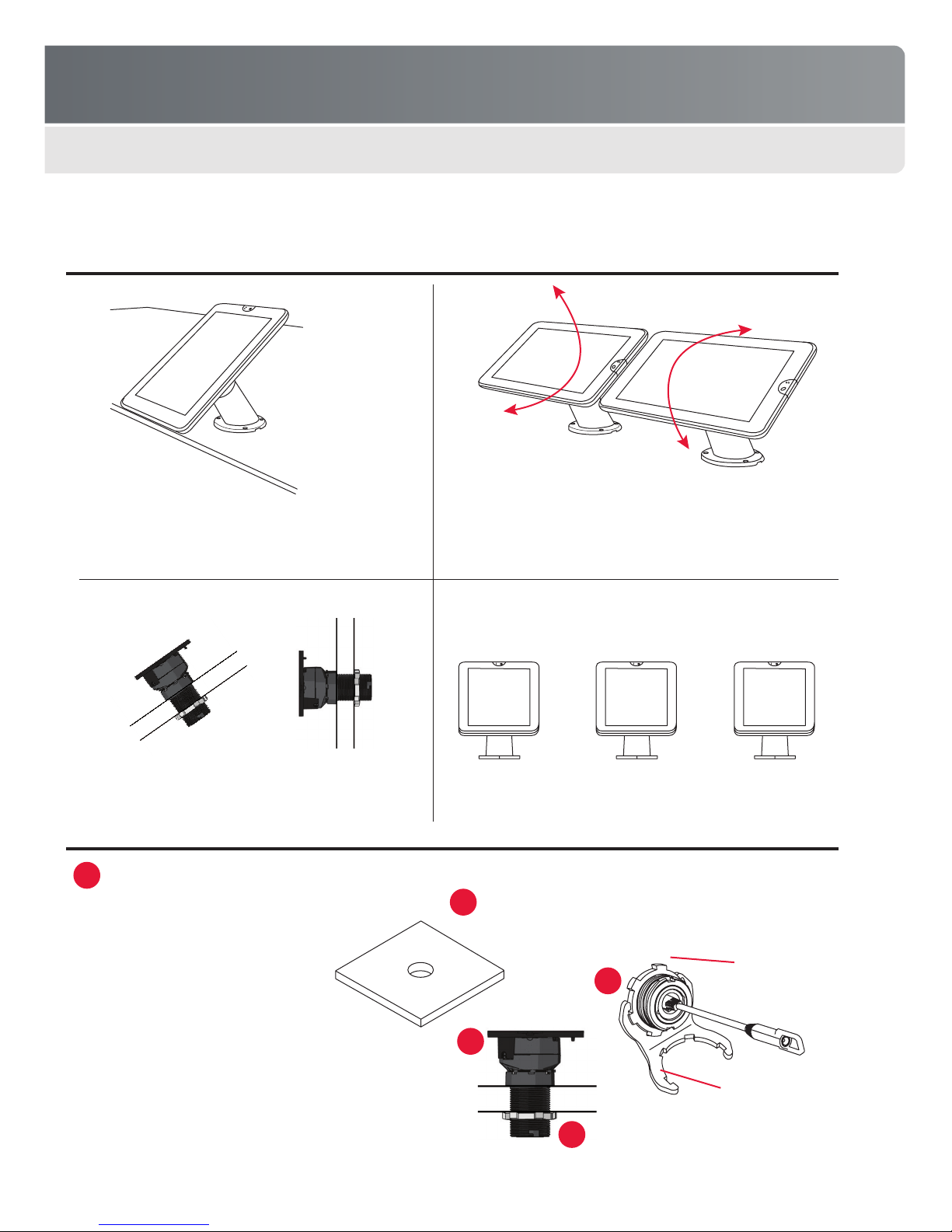
Before you begin: Review all mounting steps rst to help determine
the desired mounting location and orientation. Device must be
mounted so it does not interfere with the xture, walls, or other
positions when rotating. If device will be powered, make sure the
SmartCable will not interfere with xture, wall, or with other positions
when rotating.
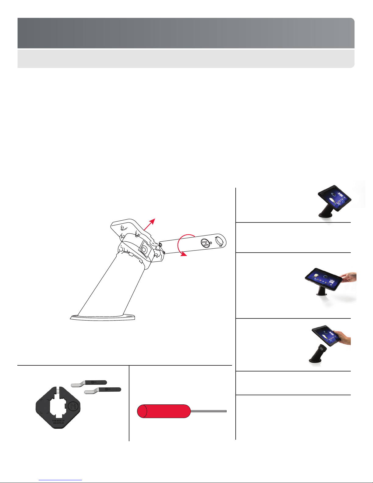
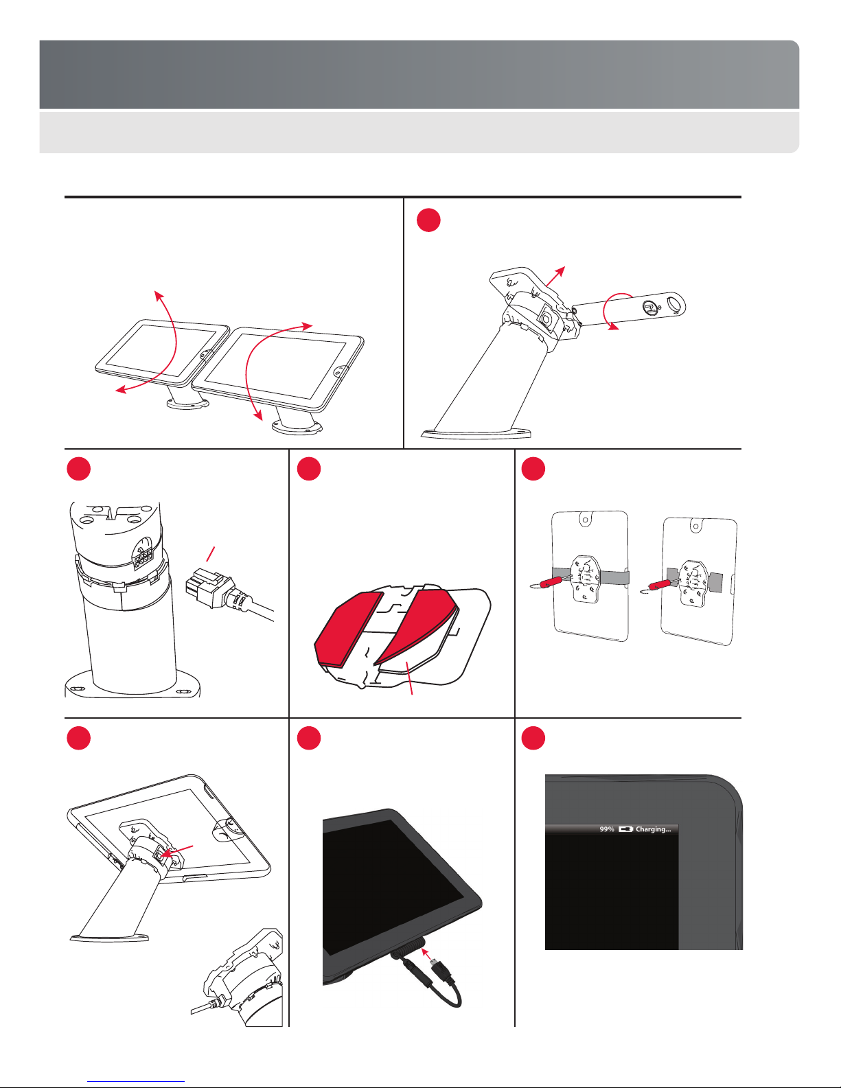
Insert key into lock, then rotate counterclockwise until your
hear a “click” indicating the lock is open. Remove the key
and then remove the saddle.
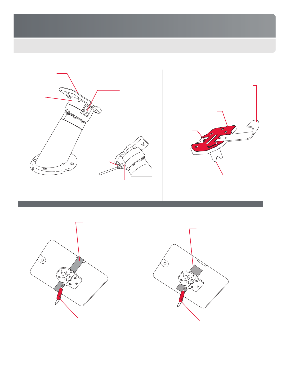
Plug SmartCable for this device into
the puck.
Place saddle with device back onto
the puck, then press the lock button
to secure.
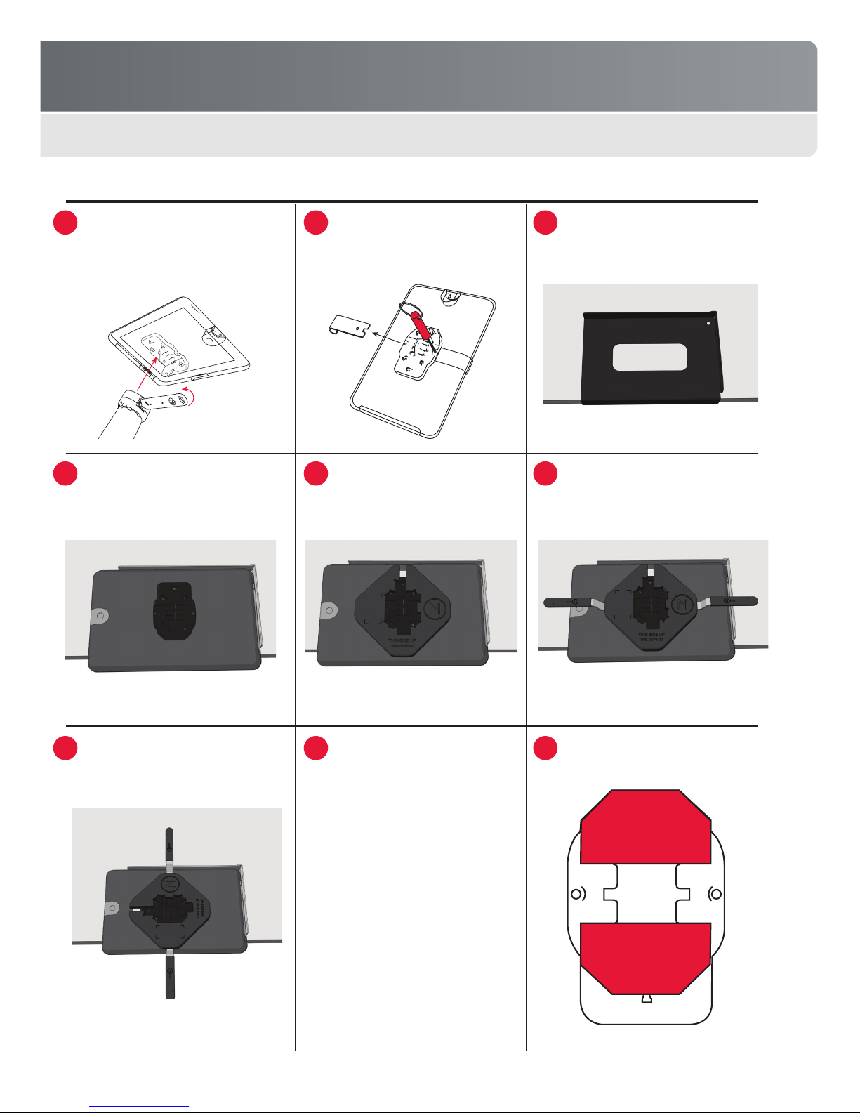
Clean back of device with alcohol
wipe, then remove covering from VHB
pad on the saddle. Center saddle
on back of the device in the desired
orientation. Press rmly to attach.
Important! Check the SmartCable fit and routing
before attaching the saddle. If a locating device
is included in your kit, use this device to place
the saddle in the correct location.
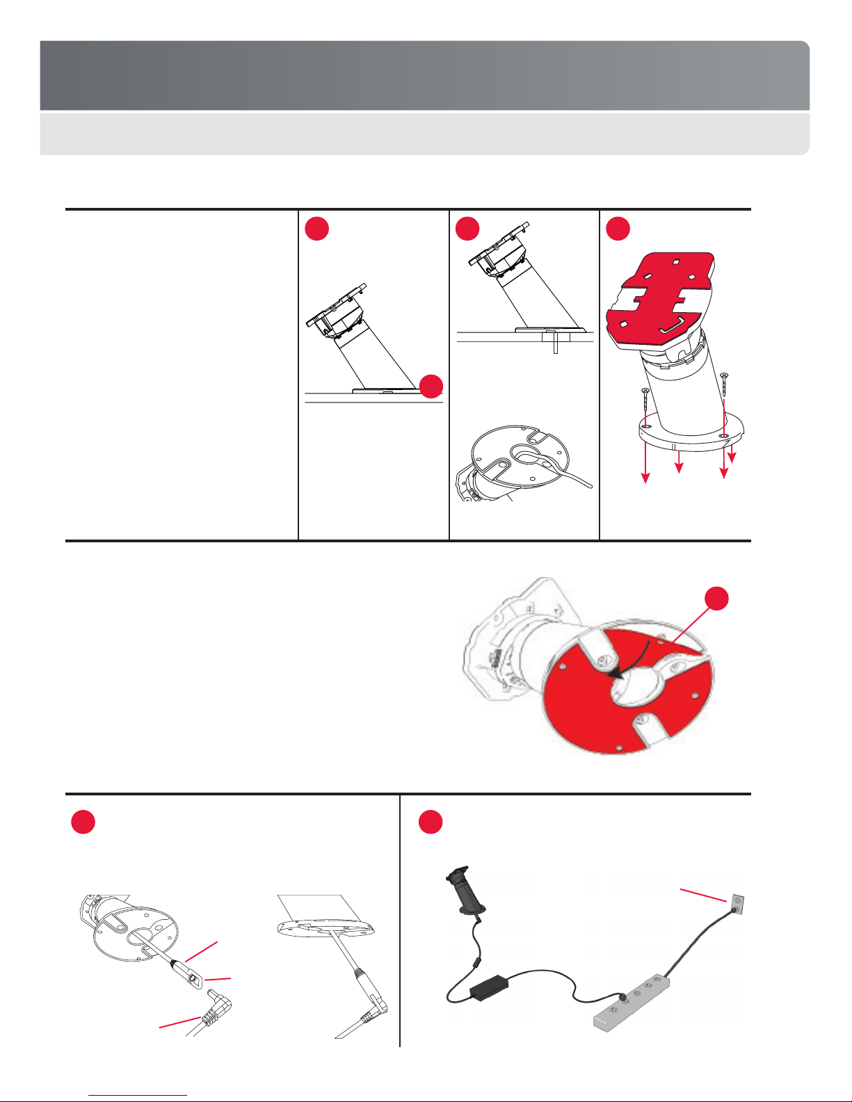
Plug loose end of SmartCable into
the power input jack on the mounted
device. Rotate device to ensure that
the cable does not interfere with the
countertop or other devices.
Use security driver to install any
optional mounting brackets.
Turn on the device and verify that it is
charging.
Note: You will hear a “click” when
the lock is open. The key is only
removable in one position.
1
2
2
3
3
4
4
Important!
SmartCables are
product specific.
Make sure you have
the correct cable for
the device you are
powering.
Important! Provide resistive
pressure on the SmartCable
connector when installing the
saddle to prevent damage. Do
not force the saddle or you
may damage the SmartCable
connector.
Note: Optional brackets or extension wings
fit into the slots on the saddle and are held
in place by two security screws.
Note: Device’s battery-charging indicator may or may
not appear immediately: device is charging.
Key
Saddle
8-pin mate-
n-lock end of
SmartCable
VHB

FREEDOM UNIVERSAL 2.0
9
FREEDOM AXIS
Removing Device from Saddle
Disconnect SmartCable (if present) from
mounted device. Insert key into lock, then
rotate counterclockwise until you hear a
“click” indicating the lock is open. Remove
key, then remove saddle and device.
Place device into the xture with the
saddle facing up.
Insert handles into slots on both sides of
the plate.
If there is an optional mounting
bracket attached, use the security
driver to remove the security screws
and bracket.
Place removal plate over the saddle.
The plate only ts on one way; be sure
it is at against the back of the tablet.
Rotate tool handles 90 degrees to free
the saddle. You may need to rotate
back and forth several times to loosen
the saddle.
Remove saddle from device. The
saddle’s adhesive pad should split in
half, leaving adhesive tape on both
device and saddle. Remove adhesive
from the device and puck using your
thumb to roll tape off the surface. Use
alcohol wipes to further clean both
surfaces.
Place removal xture over the edge of
the counter.
Place removal plate over the saddle. The
plate only ts on one way; be sure it is
at against the back of the tablet.
Install new VHB pad onto the saddle for
future use.
1
4
7
2
5
8
3
6
9

FREEDOM UNIVERSAL 2.0
10
FREEDOM AXIS
Removing Base from Fixture
If a base was mounted using VHB adhesive, use the following procedure to remove the base from the xture:
1. Turn off the system power and disconnect the power supply cable from the base.
2. Insert removal tools into notches on both sides of the base.
3. Turn each tool handle 90 degrees to free the base.
4. Remove the base. The adhesive pad should split in half, leaving adhesive tape on both base and xture.
5. Remove adhesive from base and xture using your thumb to roll tape off these surfaces.
6. Use alcohol wipes to clean adhesive residue on base and xture.

FREEDOM UNIVERSAL 2.0
11
FREEDOM AXIS
Releasing the Device
Securing the Device
OPERATION
Basic Operation & Use
Once the system is installed, simply turn on the system power and activate power to the secured device. Customers can now rotate and
demo the device in different orientations, while the system keeps the device fully powered and secure.
Using the Quick-Release Feature
The system’s quick-release feature makes it possible to remove the device from the base without removing the adhesive pad and
saddle. This makes it easy to give customers a personalized, tetherless demo experience or to perform product updates (e.g.,
upgrade the device’s rmware or apps).
Lift saddle/device
assembly from puck
Place saddle/device
assembly onto the
puck (see note at left)
Saddle
Security tab
SmartCable
connector
Disconnect SmartCable (if present)
from mounted device
Reconnect SmartCable (if
present) to mounted device
Important!
The saddle’s security tab ts
tightly around the SmartCable.
When installing the saddle,
provide resistive pressure on
the SmartCable connector to
prevent damage. Do not force the
saddle or you may damage the
SmartCable connector.
Insert key into lock and rotate counterclockwise
a full 360 degrees until it “clicks,” then remove
the key (key is only removable in one position)
Press lock button until
it “clicks” to secure
1
1
2
2
3
3

FREEDOM UNIVERSAL 2.0
12
FREEDOM AXIS
MAINTENANCE
Important! Discharge yourself of any static electricity buildup before touching any parts containing sensitive electronic components.
You can do this by placing your hand on any adjacent metal countertop or shelf unit.
Routinely check the SmartCable to ensure the cable is not damaged or worn (i.e., no kinks or no exposed wires visible through the
cable jacket) and the connectors are not bent or damaged.
TROUBLESHOOTING
All MTI products are designed and manufactured to provide consistent, trouble-free service. If the display has a problem, refer to the
troubleshooting table below. If the problem persists, contact MTI Customer Service at 1.800.426.6844 (toll-free) or 503.648.6500
(international), from 7AM - 5PM Pacic Time, Monday through Friday. Please send faxes to 866.200.9166 or e-mail cservice@mti-
interactive.com.
FCC COMPLIANCE
This equipment has been tested and found to comply with the limits for a Class A digital device, pursuant to part 15 of the FCC
Rules. These limits are designed to provide reasonable protection against harmful interference when the equipment is operated in a
commercial environment. This equipment generates, uses, and can radiate radio frequency energy and, if not installed and used in
accordance with the instruction manual, may cause harmful interference to radio communications. Operation of this equipment in
a residential area is likely to cause harmful interference in which case the user will be required to correct the interference at his own
expense.
Problem Probable Cause Solution
Device battery is not charging or only
charging intermittently
AC power plug is unplugged from the wall
outlet, or the power strip (if used) is turned off
Ensure AC power is securely plugged
into the wall outlet and the power strip
is on
Power supply is not connected to the base
adapter cable
Plug power supply into the base
adapter cable
Wrong SmartCable was used, is not
connected, or is damaged
Connect a correct and/or undamaged
SmartCable
AC cord not connected to the power supply Connect AC cord to the power supply
Base adapter cable is damaged Replace adapter cable

FREEDOM UNIVERSAL 2.0
13
FREEDOM AXIS
LIMITED WARRANTY
Seller warrants all Products manufactured by Seller to be free from defects in material and workmanship. Seller’s warranty shall
begin on the date of shipment to Customer. The length of the warranty is determined by the Product type as set forth below.
Base units, display puck assemblies (enclosure and ECB, excluding puck battery), alarm modules (enclosure and ECB),
Piezo alarms, secondary sensors, electronic security sensors, quad cables, power/data link cables, IntelliKey Switch Module
assemblies, Keyswitch assemblies, Keypad assemblies, puck adapters and custom design brackets/adapters for the Freedom™
Consumer Electronic Handheld (CEhh) Merchandising System (“Freedom™ System”), and NFC electronics boards in the
Freedom™ System, all OnSite® switching modules and video/audio switching and distribution modules for the Audition Signal
Management System (“Audition System”), multimedia players, format converters, resolution scalers and audio/video cables
for the Audition System are warranted for a period of one (1) year.
CarbonTetherTM assemblies, both powered and mechanical and SmartTetherTM assemblies are warranted for a period of one
(1) year.
AirTetherTM assemblies are warranted for a period of six (6) months.
Seller provides no warranty hereunder for Power Supplies, and Customer must rely solely upon any warranty provided by the
manufacturer of such Power Supplies. Certain manufacturer warranties are on le with Seller and may be made available upon
Customer’s request. Seller warrants all batteries to be free from defects in materials and factory workmanship, and warrants
any battery that fails to perform as specied within six (6) months after date of shipment. This warranty shall not apply if buyer
fails to notify MTI of such defect within ten (10) days after discovery, or if battery has been subjected to misuse, negligence
or accident.
The following components of the Freedom™ System are considered consumable items and Seller provides no warranty for
such items: USB interconnect cables, extension cables, SmartCables, FlexSensors, Membrane Sensors, anti-skid pads, anti-
rotation brackets, VHB adhesive pads, X- and L-brackets, CC- and DC-brackets, cable clamps, zip ties, and installation,
retrieval and removal tools. Unused SmartCables and Secondary Sensors that are demonstrated by Customer to have been
faulty upon delivery to Customer will be replaced at Seller’s expense; provided, however, Customer shall be responsible for any
and all related shipping and handling costs.
All other Seller-manufactured Products, not specied above, are warranted for a period of one (1) year.
Seller’s warranty expressed herein does not apply to the following:
• Cartons, cases, cabinets, displays, or any other unit attached to or otherwise connected to a Seller-manufactured Product.
• The labor and other costs associated with the removal and replacement of the warranted Product or any component
thereof.
• Products used in applications beyond their normal intended use, application, or rated specications.
• Products damaged by accident, abuse, improper voltage, faulty installations, mechanical failure, re, ood, lightning, civil
unrest, or any act of God.
• Warranty services rendered by any party other than Seller unless so authorized by Seller.
• Replacement parts and equipment that have been discontinued or are otherwise unavailable.
• Products from other manufacturers that are integrated by Seller into Customer’s system(s) are not warranted by Seller and
are subject only to that warranty, if any, provided by the manufacturer of such Product(s).
Subject to the limitations stated herein, and at Seller’s sole discretion, Seller will replace or repair defective Products or
components thereof at no charge to Customer so long as Customer’s account with Seller is current and Customer has returned
the Product(s) or component thereof pursuant to a properly issued Return Material Authorization.
Replacement of any Product or any component thereof by Seller under this warranty provision shall not extend, in any way, the
length of the original applicable warranty period otherwise provided for herein.
Seller reserves the right to replace a defective Product or component thereof with a refurbished Product or component.
Seller’s warranty herein is non-transferable and shall extend only to Customer.
Table of contents
Popular Computer Accessories manuals by other brands

Cooler Master
Cooler Master Cooler Master manual

Sony
Sony LFA-PC1 operating instructions

Antec
Antec KS 282 user manual

Microchip Technology
Microchip Technology MPLAB ICD 4 quick start guide

Panasonic
Panasonic TY-42TM6D - Monitor Terminal Expansion Board operating instructions

MYTORQ
MYTORQ MY-TR Operation manual