manuals.online logo
Brands
  1. Home
  2. •
  3. Brands
  4. •
  5. M2 Antenna Systems
  6. •
  7. Antenna
  8. •
  9. M2 Antenna Systems 48.5-4 User manual

M2 Antenna Systems 48.5-4 User manual

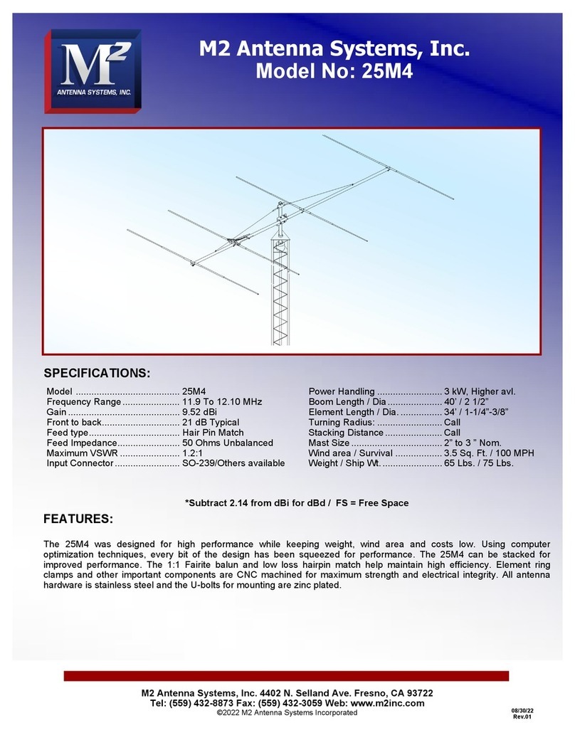
M2 Antenna Systems, Inc.
Model No: 48.5-4
M2 Antenna Systems, Inc. 4402 N. Selland Ave. Fresno, CA 93722
Tel: (559) 432-8873 Fax: (559) 432-3059 Web: www.m2inc.com
©2022 M2 Antenna Systems Incorporated
08/30/22
Rev.01
Model .........................................48.5-4
Frequency Range.......................48.3 to 48.7 MHz
Gain............................................10.39 dBi
Front to back ..............................24 dB Typical
Feed type ...................................Hair Pin Match
Feed Impedance. .......................50 Ohms Unbalanced
Maximum VSWR ........................1.5:1 Typical
Input Connector..........................“N’ Connector
Power Handling ......................... 1.5 kW
Boom Length / Dia..................... 151” / 2”
Element Length / Dia................. 143” / 7/8” - 1/2”
Turning Radius: ......................... Call
Stacking Distance...................... Call
Mast Size................................... 2” to 3 ” Nom.
Wind area / Survival .................. 2.1 Sq. Ft. / 100 MPH
Weight / Ship Wt........................ 40 Lbs. / 45 Lbs.
FEATURES:
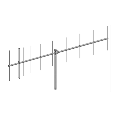
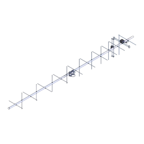
The 48.5-4 has been computer optimized from the ground up for gain and pattern covering 48.3-48.7 MHz. Originally
designed for Meteor Scatter and monitoring systems. The custom 1:1 Fairite balun and low loss hairpin match help
maintain high efficiency. Element ring clamps and other important components are CNC machined for maximum strength
and electrical integrity. All antenna hardware is stainless steel and the U-bolts for mounting are Zinc plated.
M2 antenna Systems, Inc., has well over 35 designs for Meteor Scatter applications covering from 39 MHz to 50 MHz. If
you have a specific requirement, please contact us for more details.
SPECIFICATIONS:
*Subtract 2.14 from dBi for dBd / FS = Free Space
48.5-4 ASSEMBLY MANUAL
NOTE: A cup of zinc paste (PENETROX, NOALOX, OR equivalent) has been provided to enhance the quality
of all the electrical joints in this antenna. Apply a thin coat wherever two pieces of aluminum come in contact.
1. Refer to the Dimension Sheet. Note the different boom sections and the approximate position of each
element. Slide the 2” RING CLAMP into their approximate positions on the boom sections. Note One section
also has a 1/4” hole (for “T” match block) and ALL SPACING DIMENSIONS ARE REFERENCE FROM THE
DRIVEN ELEMENT. Accuracy at this pint is unnecessary as the boom must be assembled before exact
element spacing is set. Spread the ring clamp fingers with a flat blade screwdriver if necessary to ease
movement on boom. Loosely and a 1/4-20 x 1” bolt and locknut to fingers of all clamps.
2. Return to the rear boom section. Mount the “T” MATCH ASSEMBLY BLOCK to the 1/4” hole with a single
1/4-20 x 2-1/4” bolt (make sure the Driven Element ring clamp is to the rear of the “T” match block). Orient the
two balun connectors to the front. Now slide the ring clamp up against the “T” Match block and rotate until the
element channel is on the opposite side of the boom from the “T” Match block. Tighten the 1/4-20 x 1” bolt and
locknut to hold the clamp in position.
3. Select a 7/8” x 15” CENTER SPLICE and insert a 3/4” x 36” tube section halfway into butt end. Line up
holes. Push a 1/4-20 x 1-3/4” bolt through this hole and add the second 3/4” element section. Add another bolt
and place this assembly into the Driven Element ring clamp channel. Add the 1/4” locknuts and tighten.
4. Slide the SHORTING BARS onto the swaged outer ends of the 3/4” sections and onto the 1/4” “T” Match
rods. Position them per the DIMENSION SHEET. The measurement is between the outer face of the “T” Match
block and the inner face o the shorting bar. Wipe PENETROX on the element and “T” Match rod at the correct
spot. Slide the shorting bar to this spot. Add the 8-32 x 1-1/2” screw and locknut and ALIGN the rods parallel
with the element sections and tighten the hardware. Wet the two 8-32 x 1/4” set screws with Penetrox and
thread a pair into each shorting bar. A 5/64 Allen wrench has been provided for tightening the set screws.
5. Now assemble the boom sections using the 1/4-20 x 2-1/2” bolts and locknuts. Install the BOOM TO MAST
PLATE at about 66” from the rear at this time. This plate can be clamped in a vice, turned flat and laid on a
work table or clamped to a short mast providing a good working height for the balance of the assembly.
6. Assemble the remaining 3/4” element sections and 7/8” x 15” sleeves and mount to the ring clamps as in
step #3.
7. Pair up the 1/2” tip sections by length. Install the longest pair into the REFLECTOR (rear) element. NOTE: If
you have received tips with no holes predrilled at the factory, position the 1/2” tip at the proper dimension and
drill through the holes into the 1/2” tube using a #17 (.173 dia.) drill bit. Secure with 8-32 x 1” screws and
locknuts. Repeat for all elements, using the shorter lengths forward. See the Dimension Sheet for EXPOSED
TIP LENGTHS.
8. Now adjust ELEMENT SPACING ACCURATELY following the Dimension Sheet. Since the Driven Element
is fixed, use it as the primary measurement reference. Dimensions given are “center to center”, but can also be
used for edge to similar edge measurement. After setting spacing, align elements parallel with the Driven
Element and tighten the 1/4-20 x 1” bolts in each ring clamp.
9. Install the “F” connector SEAL NUTS on the two female “F” connectors on the “T” match block. The black
neoprene seal should face out. Attach the balun to the two “F” connectors on the “T” match block. Finger tight-
en and then gently final tighten with a 7/16” end wrench. Then run the SEAL NUTS up against the face of the
male connectors and tighten gently about 1 turn with a 1/2” end wrench. Attach the coaxial PHASING LINE “N”
connector to the “T” match block and route the coax forward to the boom to mast plate. Secure the main feed
line and the coiled balun cable as required with large black cable ties or equivalent. (ties should be snug, but
not crushing cable). It is your option to further seal the “N” feed connector and balun connectors with Coax
Seal or equivalent. NOTE; The balun cable does not have be coiled up to be effective. It can be uncoiled and
secured cleanly along the boom if desired.
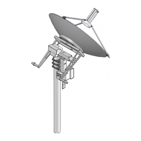
48.5-4 DIMENSION SHEET
149.0"
71.875"
77.125"
2"X71"
SHORTING BAR,
8-32 SCREW &LOCKNUT
(2) 8-32 X 1/4" SET SCREWS
2"X84"SOE
50.437"
26.688"
COIL UP RG6U BALUN CABLE
USE CABLE TIES TO SECURE
IT AND FEEDLINE TO THE
BOOM.
2" UBOLTS AND
CRADLES,
5/16"-18 NUTS &
LOCKWASHERS
'T' MATCH
ATTACH WITH 1
1/4-20 X 2-1/4"
BOLT
ELEMENT SPACING
26.688"
0.0"
2" RING CLAMP
& 1/4-20 X 1"
BOLT & LOCKNUT
21.25"
18.75"
1/4-20 X 2-1/2"
BOLT & LOCKNUTS
NOTE: ALIGN ALL ELEMENTS
TO THE DRIVEN ELEMENT.
REFERENCE ALL DIMENSIONS
TO THE DRIVEN ELEMENT.
BOOM TO MAST PLATE
MUST BE IN THE SAME
LOCATION ON ALL PHASED
ANTENNAS, 66" FROM
REFLECTOR.
8"
8-32 X 1"
SCREW &
LOCKNUT
/4 -20 X 1-3/4"
BOLT & LOCKNUT
7/8 X 15"
CENTER
SLEEVE
3/4 X 36"
26.50"
48.5-4 ASSEMBLY MANUAL
10. Mount the BOOM TO MAST PLATE as shown on the DIMENSION SHEET and secure with two 2” U-bolts,
cradles, stainless lockwashers and nuts. Two 2” U-Bolts and hardware are supplied for attaching the antenna
to the mast.
11. this completes the ASSEMBLY. When the antenna is installed in position on the mast, the main feedline
can be attached and sealed at that time. REMEMBER to support the feedline at the antenna boom and on the
mast or tower.
Carefully Manufactured By
M2 Antenna Systems, Inc.
4402 N. Selland Ave.
Fresno, CA 93722
(559) 432-8873 Fax (559) 432-3059
www.m2inc.com email: [email protected]
48.5-4 PARTS & HARDWARE
DESCRIPTION QTY
BOOM SECTION, 2” X .058 X 84” SOE................................................... 1
BOOM SECTION, 2” X .058 X 71” STR ................................................... 1
ELEMENT SECTION, 3/4” X .049 X 36” SOE.......................................... 8
ELEMENT TIP, 1/2” X .049 X SEE DIMENSION SHEET......................... 8
ELEMENT SPLICE, 7/8” X .058 X 15” (FOR 2” RING CLAMP) ............... 4
BOOM TO MAST PLATE, .250” X 6” X 8”................................................ 1
DRIVEN ELEMENT ASSEMBLY ............................................................. 1
BALUN, RG-6........................................................................................... 1
RING CLAMP, 2”...................................................................................... 4
U-BOLT AND CRADLE, 2”....................................................................... 4
ASSEMBLY INSTRUCTIONS .................................................................. 1
IN HARDWARE BAG
SHORTING BARS.................................................................................... 2
NUT, 5/16-18 SS...................................................................................... 8
LOCKWASHER, 5/16 SPLIT RING.......................................................... 8
BOLT, 1/4-20 X 2-1/2” SS ........................................................................ 2
BOLT, 1/4-20 X 2-1/4” SS ........................................................................ 1
BOLT, 1/4-20 X 1-3/4” SS ........................................................................ 8
BOLT, 1/4-20 X 1” SS .............................................................................. 4
NYLOCK NUT, 1/4-20 SS ........................................................................ 14
SCREW, 8-32 X 1-1/2” SS ....................................................................... 2
SCREW, 8-32 X 1” SS ............................................................................. 16
SET SCREW, 8-32 X 1/4” SS .................................................................. 4
NYLOCK NUT, 8-32 SS ........................................................................... 18
NUT SEAL, 3/8-32.................................................................................... 2
NYLON TIE, 14” ....................................................................................... 3
ZINCE PAST, 1 OZ ................................................................................. 1
ALLEN WRENCH, 5/64............................................................................ 1
M2ANTENNA SYSTEMS, INC.
4402 N. SELLAND AVE.
FRESNO, CA 93722
(559) 432-8873 FAX: 432-3059
www.m2inc.com Email: [email protected]

Other M2 Antenna Systems Antenna manuals

M2 Antenna Systems 167XP22 User manual

M2 Antenna Systems

M2 Antenna Systems 167XP22 User manual

M2 Antenna Systems 146CP8 User manual

M2 Antenna Systems

M2 Antenna Systems 146CP8 User manual

M2 Antenna Systems 440-6SS User manual

M2 Antenna Systems

M2 Antenna Systems 440-6SS User manual

M2 Antenna Systems 17M5DX User manual

M2 Antenna Systems

M2 Antenna Systems 17M5DX User manual

M2 Antenna Systems 2M4 User manual

M2 Antenna Systems

M2 Antenna Systems 2M4 User manual

M2 Antenna Systems FGSD-2.4DH User manual

M2 Antenna Systems

M2 Antenna Systems FGSD-2.4DH User manual

M2 Antenna Systems SYSTEM SAMPLE 3 User manual

M2 Antenna Systems

M2 Antenna Systems SYSTEM SAMPLE 3 User manual

M2 Antenna Systems 7-10-30LP8 User manual

M2 Antenna Systems

M2 Antenna Systems 7-10-30LP8 User manual

M2 Antenna Systems 2MCP22 User manual

M2 Antenna Systems

M2 Antenna Systems 2MCP22 User manual

M2 Antenna Systems FG2227-21X4CP User manual

M2 Antenna Systems

M2 Antenna Systems FG2227-21X4CP User manual

M2 Antenna Systems FG170-230-5 User manual

M2 Antenna Systems

M2 Antenna Systems FG170-230-5 User manual

M2 Antenna Systems 432-6WL User manual

M2 Antenna Systems

M2 Antenna Systems 432-6WL User manual

M2 Antenna Systems 6M6LN User manual

M2 Antenna Systems

M2 Antenna Systems 6M6LN User manual

M2 Antenna Systems 6M5XHG User manual

M2 Antenna Systems

M2 Antenna Systems 6M5XHG User manual

M2 Antenna Systems 222 HO LOOP User manual

M2 Antenna Systems

M2 Antenna Systems 222 HO LOOP User manual

M2 Antenna Systems 25M4 User manual

M2 Antenna Systems

M2 Antenna Systems 25M4 User manual

M2 Antenna Systems 440-18 User manual

M2 Antenna Systems

M2 Antenna Systems 440-18 User manual

M2 Antenna Systems KT34M2 User manual

M2 Antenna Systems

M2 Antenna Systems KT34M2 User manual

M2 Antenna Systems 440-460-11HD User manual

M2 Antenna Systems

M2 Antenna Systems 440-460-11HD User manual

M2 Antenna Systems 406-6SX User manual

M2 Antenna Systems

M2 Antenna Systems 406-6SX User manual

M2 Antenna Systems 400CP30A User manual

M2 Antenna Systems

M2 Antenna Systems 400CP30A User manual

M2 Antenna Systems 20M5-125 User manual

M2 Antenna Systems

M2 Antenna Systems 20M5-125 User manual

M2 Antenna Systems 436CP30 User manual

M2 Antenna Systems

M2 Antenna Systems 436CP30 User manual

M2 Antenna Systems 403CP20 User manual

M2 Antenna Systems

M2 Antenna Systems 403CP20 User manual

Popular Antenna manuals by other brands

Sirio Antenne SMA 55-550 installation manual

Sirio Antenne

Sirio Antenne SMA 55-550 installation manual

Ciro Mazzoni LOOP ANTENNA MIDI instruction manual

Ciro Mazzoni

Ciro Mazzoni LOOP ANTENNA MIDI instruction manual

Winegard Carryout quick start guide

Winegard

Winegard Carryout quick start guide

Sea Tel 3011W-91 installation manual

Sea Tel

Sea Tel 3011W-91 installation manual

Directive Systems & Engineering DSE2324LYRMK quick start guide

Directive Systems & Engineering

Directive Systems & Engineering DSE2324LYRMK quick start guide

Trango Systems AD900-9 Specification sheet

Trango Systems

Trango Systems AD900-9 Specification sheet

Steren ANT-100 user manual

Steren

Steren ANT-100 user manual

Metronic 415047 quick start guide

Metronic

Metronic 415047 quick start guide

Phonak TX-300V Optimization guide

Phonak

Phonak TX-300V Optimization guide

Honeywell HRA 80 Mounting instructions

Honeywell

Honeywell HRA 80 Mounting instructions

Kathrein BAS 60 Benutzerhandbuch

Kathrein

Kathrein BAS 60 Benutzerhandbuch

COBHAM SAILOR 60 GX installation manual

COBHAM

COBHAM SAILOR 60 GX installation manual

Hemisphere GPS C321 user guide

Hemisphere GPS

Hemisphere GPS C321 user guide

Lectrosonics ALP690 instruction manual

Lectrosonics

Lectrosonics ALP690 instruction manual

DX Engineering DXE-7580FS-VA-1 instructions

DX Engineering

DX Engineering DXE-7580FS-VA-1 instructions

Comet Antenna CA-52HB4 instruction manual

Comet Antenna

Comet Antenna CA-52HB4 instruction manual

HP ProCurve J8441A Guide

HP

HP ProCurve J8441A Guide

Sony SAN-18D1 installation manual

Sony

Sony SAN-18D1 installation manual

manuals.online logo
manuals.online logoBrands
  • About & Mission
  • Contact us
  • Privacy Policy
  • Terms and Conditions

Copyright 2025 Manuals.Online. All Rights Reserved.