HP ProCurve J8441A User manual

Item
Frequency, MHz 2400-2500
Gain with specied cable (dBi) 4.4
VSWR nominal 1.5:1
Weight lb. (kg) 0.3 (0.14)
Dimension, in. (cm) 9 (22.9)
Wind Surface Area ft2 (m2) 0.08 (0.007)
Wind Survival mph (km/hr) 125 (200)
Power Handling (Watts) 50
Radiating Element Plated copper laminate
Enclosure Polycarbonate
RF Connector Reverse SMA (male)
Cable 33-inch CMP Plenum
SAFETY
The HP ProCurve J8441A and all associated equipment should be
installed in accordance with applicable local and national electrical code
guidelines to ensure safe operation.
Before connecting an external antenna to an HP ProCurve Wireless
Access Point, be sure that the access point radio power levels are set
in accordance with local regulatory requirements. For information on
setting radio power levels, see
Transmit power control
in the
MSM3xx/4xx Access Points Management and Conguration Guide
.
For antenna power settings by country/region, visit the online manuals
page for your access point at www.hp.com/go/procurve/manuals.
Please read all instructions carefully before attempting to
install and use this product.
APPLICATION
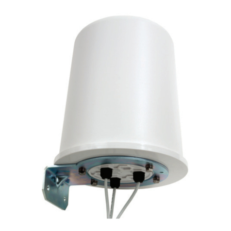
The J8441A is a high-performance omnidirectional collinear antenna
used for 2.4 GHz RF-distribution systems. Its attened radiation pattern
focuses energy along the horizontal plane to provide extended coverage
in large rooms or vaulted areas (see Figure 1). The J8441A may also be
pole-mounted for use in exterior locations.
ANTENNA LOCATION
For best results, mount the HP ProCurve J8441A at ceiling or roof level
near the center of the coverage area. A line-of-sight signal path between
the antenna and active oor location generally works best. Although
2.4 GHz signals penetrate cubical dividers and interior partitions with little
attenuation, reinforced block walls, banks of metal cabinets, glass walls,
or steel shelving may attenuate signals or cause multipath, a condition
where reected signals interfere with the primary signal. Avoid mounting
next to a column or vertical support that could create a shadow zone of
reduced coverage to one portion of the room. Each antenna comes with a
T-bar mount, an I-beam clamp, and a U-bolt style pole mount.
SPECIFICATIONS
WARRANTY AND SUPPORT INFORMATION
See the warranty and support information included with this product.
For the latest information, go to www.hp.com/go/procurve/support.
© Copyright 2010, Hewlett-Packard Development Company, L.P.
The information contained herein is subject to change without notice.
Printed in
Part Number: 5998-0306
: System grounding and lightning protection are
essential, especially for exterior-mounted antennas exposed to the
elements. Never install an antenna where it may fall and contact
electrical lines.
*5998-0307*
J8444A
*5998-0306*
J8441A
*5998-0305*
J8997A
F

HP ProCurve Networking 2HP ProCurve 4.4dBi Indoor/Outdoor Omnidirectional Antenna (J8441A) Guide
1. Attach the antenna to the antenna bracket (77) using two #6 phillips
head screws (90) and two #6 lock washers (89). Use the #6 hardware
to secure the antenna bracket to the antenna base. See Figure 2.
2. Remove the 1/4” - 20 hex nut and at washer from the runner
bracket (78) carriage bolt in preparation for mounting. Discard the at
washer–this will not be used.
3. Insert the antenna bracket (77) onto the threaded end of the runner
bracket bolt (78) as shown in Figure 2. Install the 1/4” lock washer
(16) and nut loosely–the halves of the runner bracket must slide freely
for nal installation.
4. Clamp the ceiling bracket onto the support runner and tighten the 1/4”
mounting nut using a 7/16” wrench or adjustable wrench. Secure
the coaxial cable along the support runner using tape or cable ties.
5. If installing one antenna, attach the connector to the AP Primary
antenna connection. If installing a diversity system, attach the
leads from the two antennas to the AP main and auxiliary antenna
connectors.
1. Install bracket plate (77) as shown in Figure 2.
2. Referring to Figure 2A, install I-beam clamp (80) to the bracket plate
using at washer (04), lock washer (84), and short 1/4”-20 bolt (55).
Tighten the clamp bolt to secure the antenna in place on the I-beam.
1. At the top of the pipe, using a 1/2” wrench or adjustable wrench,
secure the U-bolt (05) to the mast clamp (26) using two 5/16” nuts
(18), lock washers (19), and at washers (02). See Figure 3.
2. Install two 5/16” nuts (18) by turning them down against the nuts
securing the U-bolt of the mast.
3. Sandwich the antenna between the two antenna clamps (48) at its
base and slide this assembly onto the U-bolt. Secure in place using
two 5/16” lock washers (19), and the two remaining 5/16” nuts (18).
4. Secure the coaxial cable along the mast or pole using tape or
cable ties.
5. If installing one antenna, attach the connector to the AP Primary
antenna connection. If installing a diversity system, attach the leads
from the two antennas to the AP unit’s
Primary
and
Secondary
jacks.
F
F
F

HP ProCurve Networking 3
HP ProCurve 4.4dBi Indoor/Outdoor Omnidirectional Antenna (J8441A) Guide
Prior to installing or using this device, consult with a professional
installer trained in RF installation and knowledgeable in local regulations
including building and wiring codes, safety, channel, power, indoor/
outdoor restrictions, and license requirements for the intended country.
It is the responsibility of the end user to ensure that installation and use
comply with local safety and radio regulations.
When
connecting an outdoor antenna make sure that proper lightning surge
protection and grounding precautions are taken in accordance with local
electrical codes. Failure to do so may result in personal injury,
re, equipment damage, or a voided warranty. The HP ProCurve
hardware warranty does not cover damage caused by static discharge
or lightning strike.
For external applications, it is strongly recommended that you install a
lightning arrester (HP J8996A or equivalent) for each port of the antenna.
Lightning arresters must be purchased separately.
For best results, install the lightning arrester in close proximity to a
low-resistance ground connection near where the coaxial cable
enters the building or attaches to an AP. For exterior installations,
use weatherproof coax connectors with a suitable mastic or
rubberized tape to prevent water incursion. See Photo 1.
To connect the lightning arrester to the ground, use a very short and
direct run of #8 solid copper wire, or equivalent. Ensure that the other
end of the grounding wire connects to a true earth ground according to
the NFPA 70 National Electrical Code and/or all pertinent local codes.
Lightning arresters require periodic inspection and replacement.
Provide drip loops in cables to prevent water from entering the
building or AP. See Photo 2.
Key Size
78 Grid Bracket – 1
16 Int Tooth Lock Washer 1/4” (00.0) 1
77 Bracket Plate – 1
89 Int Tooth Lock Washer #6 2
90 SS Machine Phillips
Screw 6-3/32 x 1/4” 2
80 I-beam Clamp – 2
04 Flat Washer 1/4” 1
84 Split Lock Washer 1/4” 1
55 Hex Head Bolt 1/4 x 20 x 1/2” 1
18 SS Hex Nut #8-18 x 3/4” 6
19 SS Lock Washer 5/16” x (00.0) 4
05 U-bolt – 1
26 V-bracket – 1
48 Base Bracket – 2
02 Flat Washer 5/16” 2
Table of contents
Other HP Antenna manuals