Ciro Mazzoni LOOP ANTENNA MIDI User manual

1
2
ITALIANO
40
ENGLISH
41
Introduction
Thank you for purchasing LOOP ANTENNA.
You are the owner of the best magnetic loop ever produced worldwide,
professional or otherwise.
We are certain that, after having carefully read this manual, correctly assembled
the antenna and familiarised yourself with the LOOP ANTENNA, this product will
bring you a great deal of enjoyment and satisfaction.
Overview of the project
The LOOP ANTENNA was designed for radio operators who have limited space for
their antenna, yet still want a quality antenna that meets their needs.
The antenna has smaller dimensions, but high efficiency in order to compete with
the classic dipole. The antenna bandwidth covers more than one band within the
amateur radio frequency allocations, as well as enough bandwidth to support
commercial, military and civil use.
The antenna was designed and produced by a entrepreneur , who dedicated his
professional life to experimentation and testing in order to produce such a
superior product.

42
Mechanical assembly
Specialised equipment was used to correctly shape the aluminium tubular
elements to guarantee the structural integrity of the LOOP ANTENNA.
T.I.G. (Tungsten Inert Gas) was used to ensure optimal
contact and strength.
The only movable section in the loop is at the bottom.
The specially-shaped blade, made of stainless steel, is
anchored on each semi-loop with three stainless bolts
and anti-oxide paste is applied in the contact point.
The robust mast clamp is made from stainless steel and
support a pole from ø 50 to 60mm
(2.0in – 2.3in).
The MIDI LOOP is built in four sections and to ensure contact between these
sections, precision grooved flanges are used.
43
Where to install the LOOP ANTENNA
This antenna can operate from almost any place.
However, only an outdoors site can guarantee communication at short, medium
and long distance with the best S.W.R.
To achieve the S.W.R. diagram shown in the technical specifications, we highly
recommend installing the LOOP ANTENNA as follows:
leave at least 2 metres (6.56ft) all around
minimum and maximum height, from ground (or reflective surface) to the base
of the antenna, are:
baby LOOP
min 1.5m (4.92ft) - max 2.5m (8.20ft)
MIDI LOOP
min 2.5m (8.20ft) - max 4.0m (13.12ft)
Safety information
Read carefully this instruction manual before installation and use.
Ciro Mazzoni Radiocomunicazioni assumes no liability if incorrect or dangerous
installation practices are used.
select your installation site with safety, as well as performance, in mind
WARNING
INSTALLATION OF THIS PRODUCT NEAR POWER LINES IS DANGEROUS.
FOR YOUR SAFETY, FOLLOW THE BELOW INSTALLATION INSTRUCTIONS.
44
electric power lines and phone lines look alike. For your safety, assume
that any overhead lines can kill you
ensure proper grounding of the mast of the LOOP ANTENNA
when installing your antenna, do not use a metal ladder
do not work on a wet or windy day
do dress properly, wearing shoes with rubber soles and heels, rubber
gloves, long sleeve shirt or jacket
be sure to tighten the bolts and nuts to the correct level
DO NOT STAY near the antenna while transmitting
do not use LOOP ANTENNA near people and/or animals
MOTOR CABLE
The type of motor cable depends on the distance between the LOOP ANTENNA and
the A.T.U.
- up to 20 metres (65.62ft) => 2x0.75 (2x18 AWG) cable needed
- from 20 to 30 metres (65.62 – 98.43ft) => 2x1.50 (2x15 AWG) cable needed
- over 30 metres (98.43ft) => 2x2.50 (2X13 AWG) cable needed
The BABY LOOP
The BABY loop is very easy to install.
We ship the BABY LOOP fully assembled to Maninland Europe only.
We send the BABY LOOP unassembled to all other destinations.
45
Assembled BABY LOOP packaging contents
Art. Description Quantity
0101
0102
0106
Antenna assembled ready to install
Stainless steel mast clamp and hardware
Accessory box with:
1 loop controller ATU
1 power supply for ATU
1 USB keyboard for ATU
1 bolts kit
1 instruction manual
1
1
1
Unassembled BABY LOOP packaging contents
Art. Description Quantity
0101S
0102
0107
Antenna unassembled split in two
Stainless steel mast clamp and hardware
Accessory box with:
1 loop controller ATU
1 power supply for ATU
1 USB keyboard for ATU
1 bolts kit
1 wrench key ø5
1 wrench key ø6
1 onti-oxide paste
1 instruction manual
1
1
1

46
How to assemble the BABY LOOP unassembled
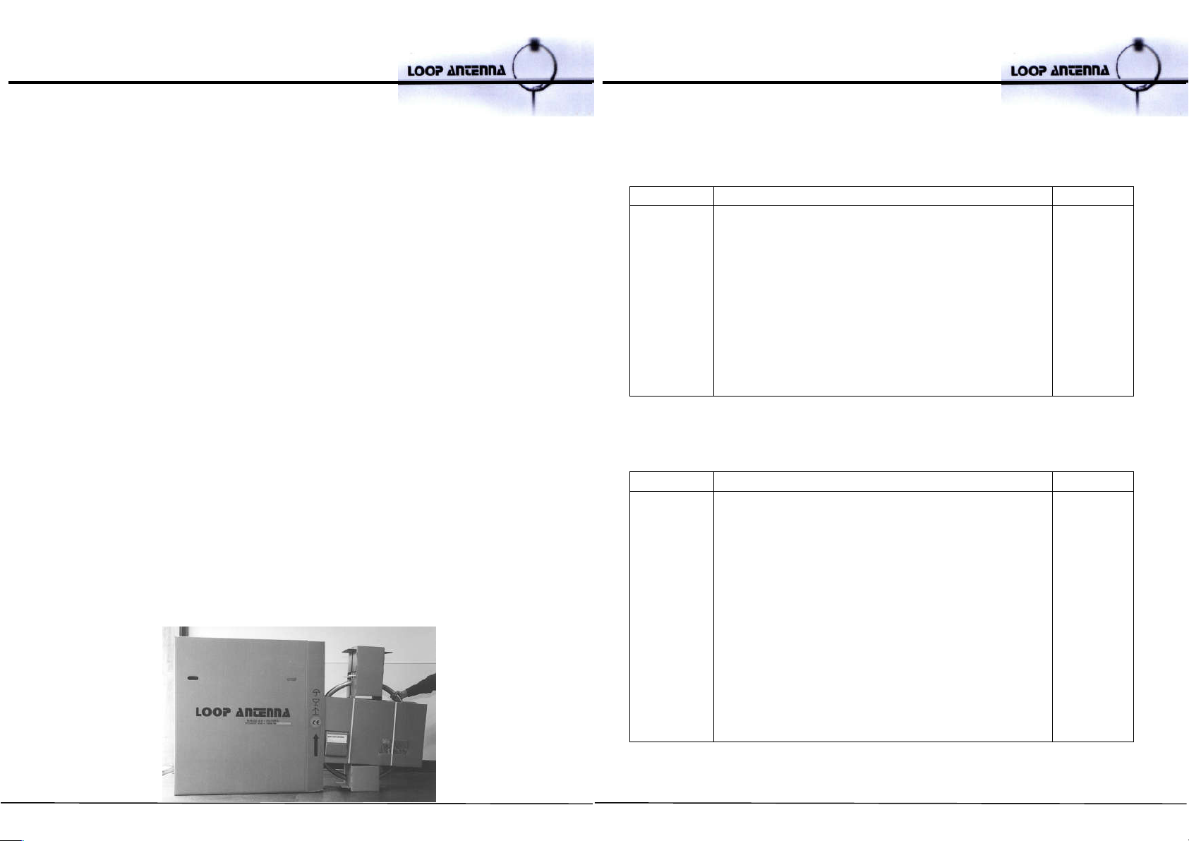
This is the BABY LOOP removed from the cardboard box.
First, remove the mounting clamp and the small cardboard box.
In the box, you will find the ATU loop controller and 2 hexagonal wrenches.
Take the two halves of the
loop and carefully lay them
on lid of the package.
Remove the packaging
holders from the two halves
of the loop and from the
capacitor. Mount the clamp
on a mast
47
Put the half of the loop
with the actuator on the
mounting clamp and
fasten it with the bolts.
Then, remove the steel
pin with the supplied
hexagonal wrench.
Remove the bolts from
the other half of the loop.

48
Put it on the mounting clamp.
Carefully slide one of the variable capacitor blades inside the other fully and the
junction blade over the half of the loop.
49
Gently insert the steel pin, using a
plastic hammer to secure it.
When it is fully engaged, fit the
washer and the bolt, then tighten
them.
DO NOT FORGET THE WASHER!!
50
Put the actuator end in place, install the bolt and place the self-locking stainless
nut on it. Tighten the nut until it reaches the surface of the isolated arm.
DO NOT FORCE IT
Now connect the loop junction blade. Spread the anti-oxide paste (provided)
inside the joint before installing the retaining bolts.
51
Fit the washer and the bolts. Tighten them with a wrench.
Now your BABY LOOP ANTENNA is ready
Enjoy and good QSO!!!

52
How to install the BABY LOOP
Provide suitable support by using a pole with a diameter from 50mm to 60mm
(2.0in– 2.3in) and a height from 1.5m to 2.5m (4,92ft-8,20ft), depending on the
surface upon which the mast is mounted.
However, if the surface is sloping, the antenna must be set higher than if the
surface is flat.
Please note that the surface upon which the mast is placed must not be made of
wood, fibreglass or plastic.
Run a 2-wire electrical cable with a minimum section of 0.75mm2 (18AWG) (for
distances up to 20 metres/65.62ft) from the sealed housing of the antenna base to
the pin terminal block on the back of the controller.
If the distance between antenna and automatic controller exceeds 20 metres,
please see page 5 – MOTOR CABLE
Run a coaxial cable (type RG213 or similar) from the SO connector on the pigtail
cable of the GAMMA MATCH antenna to the ANTENNA connector on the back of
the automatic controller.
Now you can proceed to the first turn on – page 75.
53
How to assemble the midi LOOP
MIDI LOOP packaging contents
Art. Description Quantity
0204
0206
0208
0210
0212
0218
Tubular section with flange and friction bearing
Tubular section with flange and variable capacitor
pack blades
Tubular section with flange, variable capacitor pack
blades and actuator
Tubular section with flange, base box and gamma
match
Mast clamp in stainless steel with hardware
Accessory box with:
1 Loop controller ATU
1 ATU power supply
1 USB keyboard for ATU
4 bolts M12x30
4 washers M12
1 stainless steel pivot pin 18x120
2 countersunk head hexagon socket drive screws M8x20
2 stainless steel washers M12
12 stainless steel bolts M8x40
12 stainless steel washers M8
12 stainless steel self locking nuts M8
1 stainless cap head hexagon socket drive screw M8x35
1 stainless steel self locking nuts M8 inox
1 anti-oxide paste
1 hex wrench ø5
1 hex wrench ø6
1 instruction manual
1
1
1
1
1
1

54
The MIDI LOOP removed from the cardboard box.
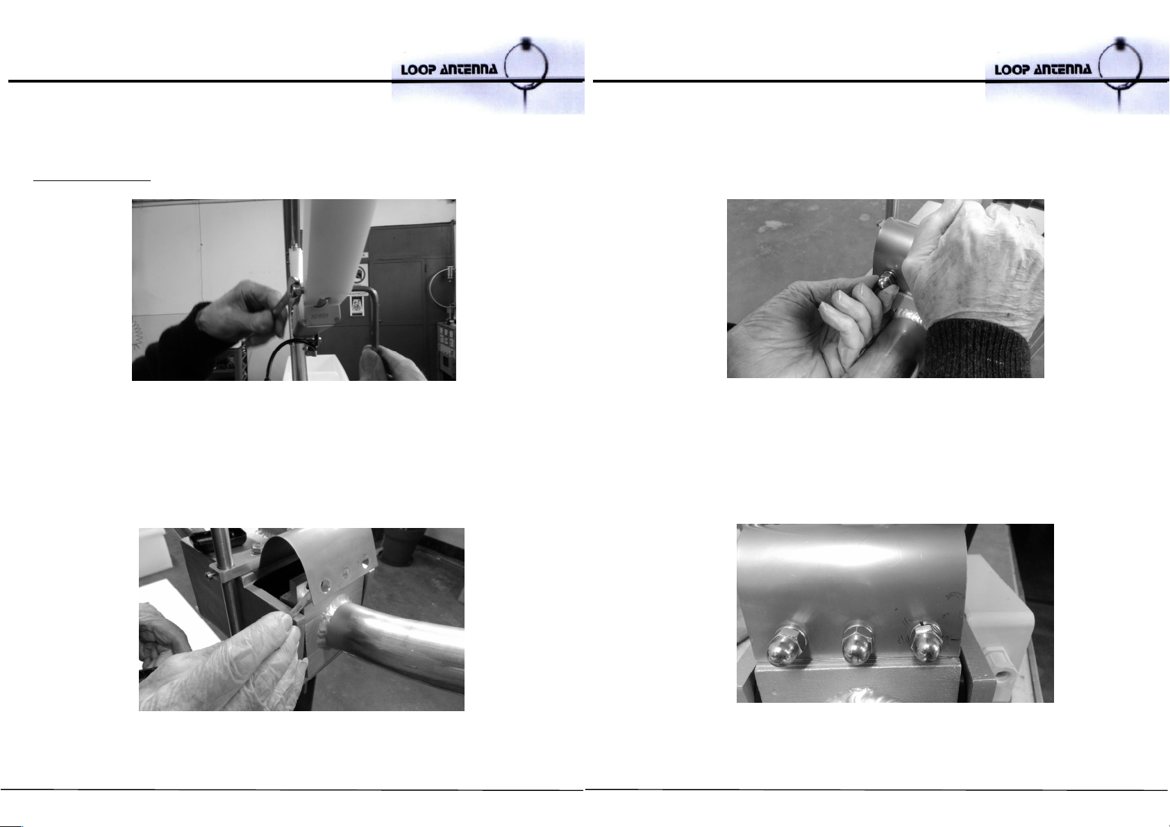
Semi-loop assembly
The first step is to join the two arch
sections (which will form the semi-loop) by
fitting together the two precision flanges.
55
Spread the provided anti-
oxidant paste on the flange.
Then fit together the two semi-loop parts, ensuring that the two flanges guides are
perfectly matched.

56
Tighten the two flanges, using the
stainless steel bolts and self-locking
nut.
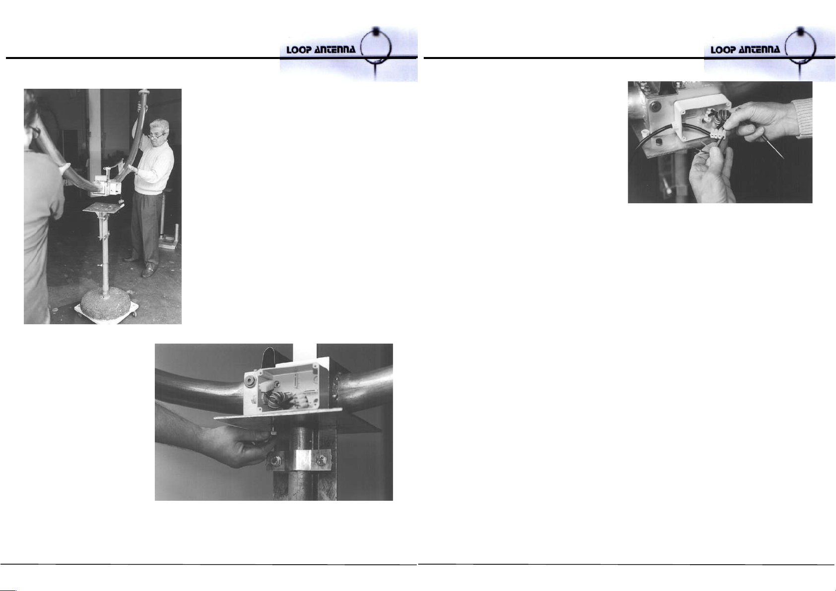
The same operation is required to assemble the other semi-loop. Before joining
the second semi-loop, it’s necessary to feed the actuator power line through the
two aluminum tubes and flanges. This can be done by hooking the power line to
the string already inside the tube.
57
Pull the full length of the power
cable through the tubes, then
push it through the hole in the
base, into the distribution box.
The box in the picture hosts the
cable terminal strip and the RF
filter.
After spreading the anti-oxide paste in the grooved
flanges, unite the flanges and install the bolts and nuts.

58
Place the bottom section of the semi-loop
(with the housed friction bearing) on the
base plate. Then insert the steel pin, which
will allow the loop of the semi-loop to
swing a few degrees.
Using a plastic hammer, fully insert
the pin. Do not use excessive force.
If necessary, gently move the semi-
loop until the pin is in place.
When the pin is fully engaged,
install the washer and the bolts.
then tighten them. A 6mm (0.23in)
wrench is provided for this.
DO NOT FORGET THE WASHER!
59
Positioning the teflon guide with
both hands, fully slide the
variable capacitor blades into one
another. Do not bend the blades
in the process.
With the capacitor fully closed, the piston-
head will enter the isolated arm. This arm is
anchored to the semi-loop as shown in the
next picture.

60
After the piston-head is in place, install the fix
cap head hexagon socket drive screw with self-locking nut. Tighten the nut until it
reaches the surface of the isolated arm. Do not force it.
The picture shows the assembled
part.
61
Now connect the semi-loop junction
blade. Spread the anti-oxidant paste
before installing the retaining bolts.
Install the washers and bolts, then
tighten them with a wrench. Now
your LOOP ANTENNA is complete.
62
Now your LOOP ANTENNA is assembled,
put it on the mounting clamp.
The mounting clamp will be anchored to
the mast as shown in the picture.
Fix the antenna onto the
mounting clamp with the
bolts.
63
Connect the power cable from the
loop controller ATU to the cable from
the actuator. The connecting terminal
is equipped with an RF suppression
toroid.
Now you can proceed to the first turn on – page 75.

64
Electrical and mechanical specifications of BABY loop
Electrical specifications
Continuous frequency coverage 6.6-29.8 MHz
S.W.R. 1,3:1 (typical)
Front to back ratio: 6 dB
Front to side ratio: 25 dB
50 Ohm input with gamma match short circuited
(electrostatic discharge protection).
Negligible noise and harmonics.
L = 3 μH Q = 1.100 a 7 MHz
C = 400 pF a 17 KV r.m.s.
Power rating: 450 W up to a 21 MHz **
1 KW from 22 to 29.8 MHz**
Bandwidth : 4 KHz @ 7 MHz
6 KHz @ 14 MHz
12KHz @ 21 MHz
20KHz @ 28 MHz
Gain compared to /2 dipole. (1 point "S" = 6 db)
- 4 dB @ 7 MHz
- 0.3 dB @ 28 MHz
**NOTE:
with this LOOP ANTENNA the peak power
is equal to the continuous power
65
Mechanical specifications
Antenna diameter 1.0m (39.8in)
Aluminum alloy 60/60 T.I.G. welded (
Tungsten Inert Gas
)
Tubular elements Ø 50 x 2mm thickness (1.9in x 0.08in)
All stainless steel hardware and support pin
Stainless steel mounting clamp for a mast of Ø 50÷ 60mm (2.0in – 2.3in)
Net/gross weight 16/26kg (26.5lbs/57.3lbs)
Windload 0.25m2 (2.7ft2)
Maximum wind velocity supported 161km/h (100mph)
Force exerted on antenna by wind of 129km/h (80.15mph) = 240 N
Maximum flexibility on the antenna base anchoring point to a metal mast Ø 6cm
(2.36in) height 3.0m (9.84in) = 720 N/m
Note:
C.E.I. regulations require the installation of wind-guys for areas of high wind with
possible ice formation (in this case NON metallic guys)

66
Electrical and mechanical specifications of MIDI loop
Electrical specifications
Continuous frequency coverage 3.5-14.5 MHz
S.W.R. 1.2:1 (typical)
Front to back ratio: 6 dB
Front to side ratio: 25 dB
50 Ohm input with gamma match short circuited
(electrostatic discharge protection)
Negligible noise and harmonics
L = 4.5 μH Q = 1.500 a 3.5 MHz
C = 560 pF a 14 KV r.m.s.
Power rating: 300 W from 3.5 to 7 MHz **
800 W from 8 to 14.5 MHz**
Bandwidth : 4 KHz @ 3.5 MHz
6 KHz @ 7.0 MHz
10KHz @ 14.0 MHz
Gain compared to /2 dipole (1 point "S" = 6 db) :
- 4 dB @ 3.5 MHz
- 0.3 dB @ 14.0 MHz
**NOTE:
with this LOOP ANTENNA the peak power
is equal to the continuous power
67
Mechanical specifications
Antenna diameter 2.0m (78.7in)
Aluminium alloy 60/60 T.I.G. welded (
Tungsten Inert Gas
)
Tubular elements Ø 75 x 2mm thickness (2.9in x 0.08in)
All stainless steel hardware and support pin
Stainless steel mounting clamp for a mast of Ø 50÷ 60mm (2.0in – 2.3in)
Net/gross weight 20/32kg (44.1lbs/70.5lbs)
Windload 0.5m2 (5.38ft2)
Maximum wind velocity supported 161km/h (100mph)
Force exerted on antenna by wind of 129km/h (80.15mph) = 480 N
Maximum flexibility on the antenna base anchoring point to a metal mast Ø 6cm
(2.36in) height 3.5m (11.48in) = 1680N/m
Note:
C.E.I. regulations require the installation of wind-guys for areas of high wind with
possible ice formation (in this case NON metallic guys)

68
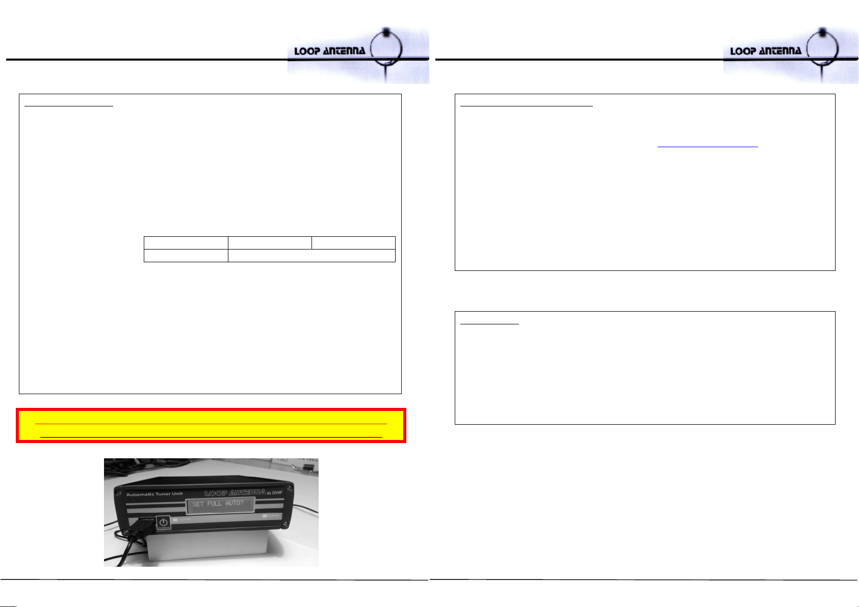
AUTOMATIC TUNER UNIT 2.0
Instructions for correct usage of the A.T.U. 2.0
- plug in the power supply and turn on the device. The display will show the
home screen version of the installed firmware
- after 3 seconds, the display will show the last tuned frequency and the S.W.R
value
- during the tuning procedure (both manual, semi-automatic and automatic)
the red TUNING LED will light up
- the blue MOTOR LED lights up only when the motor is being powered and is
actually connected.
WARNING! NEVER TRANSMIT WHEN THE ATU IS TUNING (RED LED ON)!
THERE IS RISK OF BLOWING OR BURNING OUT THE ATU RF AMPLIFIER
First of all, set which type of LOOP ANTENNA - do you have MIDI or BABY?
for the first time ONLY!!!
SET LOOP TYPE
- press the – key for 3 seconds
- the display will show SET FULL AUTO?
- press the + key once. The display will show SET ANT. TYPE
- press ENTER
- scroll through the option using the + button
- AUTO DETECT?
the ATU tests the motor polarity and the minimum and maximum freque
ncy.
After the procedure, the antenna pattern will be detected and the default
parameters for the specific model will load.
- BABY/STEALTH?
- MIDI?
- press ENTER to confirm the choice
69
- if, when tuning the loop, the blue LED does not light up, this could mean that the
motor is not drawing any current.
Possible reasons for this include:
the motor is not correctly connected or not connected at all:
check the motor cable and the connections by the AUTODETECT MODE
the motor is at the stroke end:
type a different frequency and tune again
the motor is faulty:
contact customer support
- If there is no keyboard, you will see the message WAIT KEYBOARD.
- The message WAIT KEYBOARD is disabled if ATU is configured for FULL
AUTO MODE (available only with the optional card I/O RS232 interface).
ATU input power is 200W MAX
If you wish to use an R.F. power amplifier of more than 200W, you can, of
course. Install it BETWEEN the controller ATU and the LOOP ANTENNA
AUTOMATIC TUNE MODE
- Press the * key, type the desired frequency in KHz and press ENTER (e.g. for
10,000 MHz : * 10000 ENTER)
- Press ENTER to repeat the last set frequency (already on the display)

70
If the minimum level of SWR is > 3, the red LED flashes and
the message "WARNING: SWR> 3 - PRESS ANY KEY" will show.
PROCEDURE FOR MANUAL TESTING OF MOTOR CONTROL
- Press the / for 3 seconds
- Enter the tuning frequency in KHz and press ENTER
- The display shows the frequency set on the second line and the SWR
measured in real time
- You can operate the motor by pressing 9 (to open) and 3 (to close) – HIGH SPEED
- You can operate the motor by pressing 8 (to open) and 2 (to close) – LOW SPEED
- You can operate the motor by pressing 7 (to open) and 1 (to close) – FINE TUNING
- The blue LED indicates that there is power being consumed by the motor
- To return to the home screen, press BACK SPACE
71
FULL AUTO MODE and SEMI AUTO MODE
The ATU 2.0, with the I/ORS232 plug and play card, can interface via RS232 port with the
most popular HF radios on the market:
ICOM
with CT-17c cable by LOOP ANTENNA or
with opt. CI-V CT17 interface and DB9f/DB25m cable
YAESU via DB9 CAT port and DB9 f/f cable
via 8 pin port and CT-62 cable
KENWOOD – ELAD Duo with DB9 f/f cable
ELECRAFT with Elecraft KXSER cable
FLEX Radio with DB9 (9-pin) cable – USB to RS232 Adapter null modem
Cables are available at www.ciromazzoni.com/shop
Follow the below operating procedure to use these modes and select the radio connected
to the ATU 2.0
FULL AUTO MODE
- Press the – key for 3 seconds
- The display will show SET FULL AUTO?
- Press ENTER
- Scroll through the menu with + button:
- ICOM MODE
- the ATU automatically scans to detect the address of the ICOM transceiver connected
(ref. to CT17 manual). When the scan is complete, the ID is displayed on the device
detected and will ask the operator to confirm the setting. You can cancel scanning at any
time by pressing the DELETE key or the BACKSPACE key.
- CAT MODE
- CAT YAESU CT-62 - YAESU 8 pin data port (eg. FT-817/ 857 / 897)
- DISABLED - to exit FULL AUTO MODE
- Press ENTER to confirm
- When you set the ATU in FULL AUTO MODE, the working frequency is read
continuously from the transceiver. Also, the calibration is performed automatically
when the set frequency differs in the range of 2 KHz 1,7-10MHz, and 3 KHz in the
range 10-30MHz
- Automatic re-calibration starts when the frequency of the RTX has not changed for at
least three seconds.
FLEX Radio ELAD Duo ELECRAFT
KENWOOD YAESU (RS232 data port)
72
SEMI AUTO MODE
- Press the – key for 3 seconds
- Scroll through the options using the button + then, choose SET SEMI AUTO?
and press ENTER
- Scroll through the menu with + button:
- ICOM MODE
- the ATU automatically scans to detect the address of the ICOM transceiver connected (ref.
to CT17 manual). When the scan is complete, the ID is displayed on the device detected
and will ask the operator to confirm the setting. You can cancel scanning at any time by
time by pressing the DELETE key or the BACKSPACE key.
- CAT MODE
- CAT YAESU CT-62 - YAESU 8 pin data port (eg. FT-817/ 857 / 897)
- DISABLED - to exit SEMI AUTO MODE
- Press ENTER to confirm
- When you set the ATU in SEMI AUTO MODE, the red LED starts blinking once
the transceiver has been tuned and the frequency remains unchanged for at
least one second.
- Press ENTER to start the auto tuning.
- In this mode, automatic re-calibration starts only when you press the ENTER
key.
FLEX Radio ELAD Duo ELECRAFT
KENWOOD YAESU (RS232 data port)
WARNING! NEVER TRANSMIT WHEN THE ATU IS TUNING (RED LED ON)!
THERE IS RISK OF BLOWING OR BURNING OUT THE ATU RF AMPLIFIER
73
UPDATING THE FIRMWARE
• Disconnect the power connector and the keypad on the device
• Save the cml_XXX.tes file (available on the www.ciromazzoni.com download
page) onto an empty USB drive (2/4/8 GB recommended)
• Insert the drive into the USB port on the front panel
• Switch on the device
• After a few seconds, the display will start flashing, showing the progress of the
update. This will last about a minute
• After the update, you will see the message: UPGRADE OK, REMOVE USB
MEDIA. Remove the USB drive
• The upgraded system will boot and you can reconnect the keypad
REMEMBER:
If you have two antennas in close proximity and both are set at a similar
frequency, there is a risk of blowing or burning out your shack equipments.
When operating with any other HF antennas, to protect your ATU 2.0, we
recommend short-circuiting its output antenna connector to the LOOP in
order to prevent any R.F. feedback.

74
FIRST TURN ON
At the first turn on, the ATU is in “manual mode” and you can digit the frequency
directly from the keyboard.
Now you can try to test the proper functioning of the LOOP ANTENNA:
place the BABY LOOP between 1.5m (4.92ft) and 2.5m (8.20ft) above the
ground or reflective surface
place the MIDI LOOP between 2.5m (8.20ft) and 4.0m (13.12ft) above the
ground or reflective surface
place the LOOP ANTENNA leaving at least 2 metres (6.56ft) all around
connect coaxial and motor cables to the antenna
ATTENTION: lay both the cables without spirals
75
connect the coaxial cable and the motor cable to the ATU
connect the ATU to the radio
turn on the ATU
first of all you have to set your LOOP ANTENNA type
press the – key for 3 seconds
the display will show SET FULL AUTO?
press the + key once. The display will show SET ANT. TYPE
press ENTER
scroll through the options using the button +
select BABY/STEALTH? or MIDI?

76
press ENTER to confirm
Now we are ready to operate with LOOP ANTENNA
press * and the display shows: Set Frequency
digit on the keyboard 7050 and press ENTER
the ATU turns on the RED L.E.D. and after turns on the BLUE L.E.D. when
the motor starts moving
after 5 second the motor stops and the ATU display shows the S.W.R.
value
TROUBLESHOOTING
PROBLEM CAUSE SOLUTION
Motor doesn’t work
1. the cable from
antenna to ATU is
damaged or not
connected
2. the motor cable is
inverted
1. check or replace
the cable
2. reverse the motor
cable on the rear of
the ATU
ATU doesn’t turn on
1. power supply is
faulty
2. problem with the
220V AC socket
1. replace power
supply
2. use another socket
Keyboard doesn’t
type any key
1. keyboard is
damaged
2. the keyboard may
not be connected
to the ATU
1. replace the
keyboard
2. connect the
keyboard to the
ATU
77
ATU doesn’t find
antenna type in
AUTO DETECT mode
ATU doesn’t find
antenna type in
AUTO DETECT mode
1. the coaxial cable is
short-circuited
2. the coaxial
connectors aren’t
grounded
3. there are some
metallic structures
too close to the
antenna
4. the antenna is too
close to the ground
5. the antenna is too
high above the
ground
6. the motor cable
doesn’t work
1. check the cable
2. check the
connector on the
cable
3. reposition the
antenna
4. reposition the
antenna
5. reposition the
antenna
6. check or replace
the cable
S.W.R. is too high on
low bands
1. the coaxial cable is
short-circuited
2. the coaxial
connectors aren’t
grounded
3. there are some
metallic structures
too close to the
antenna
4. the antenna is too
high above the
ground
1. check the cable
2. check the
connector on the
cable
3. reposition the
antenna
4. lower the antenna
(the right height
from a flat surface
is 1.5m)
S.W.R. is too high on
high bands
1. the coaxial cable is
in short-circuited
2. the coaxial
connectors aren’t
grounded
1. check the cable
2. check the
connector on the
cable
Table of contents
Languages:
Other Ciro Mazzoni Antenna manuals


Popular Antenna manuals by other brands


Shively Labs
Shively Labs 6842 Instruction Manual Installation, Operation, & Maintenance

DH Wireless Solutions
DH Wireless Solutions MAST Assembly guide

Simrad
Simrad TV45 manual

TechniSat
TechniSat DIGIDISH 33 installation instructions

axing
axing TAA 3-10 Operation instructions

Axcess
Axcess AT-132-A-PT quick start guide


