!
!
3200
750
1050
140
0
600
310
2970
2720
2610
2560
Instruction Manual
Thank you for purchasing our product.
For your safety :
Read this manual carefully for proper handling and operation before using.
Keep this manual in a safe place for future reference.
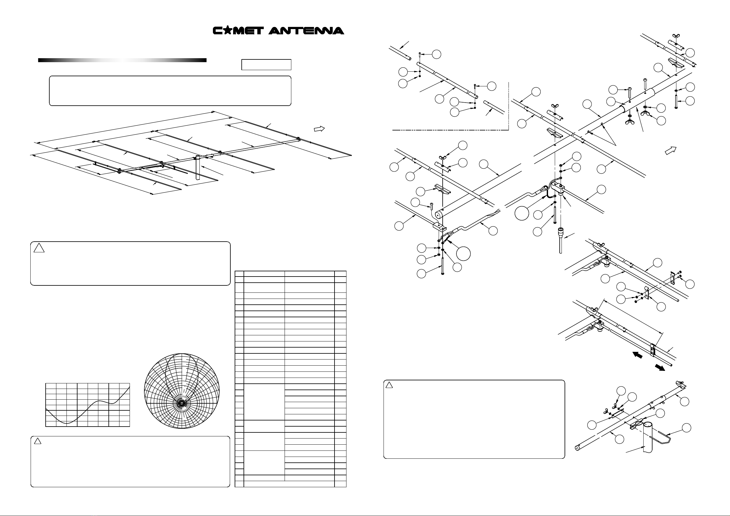
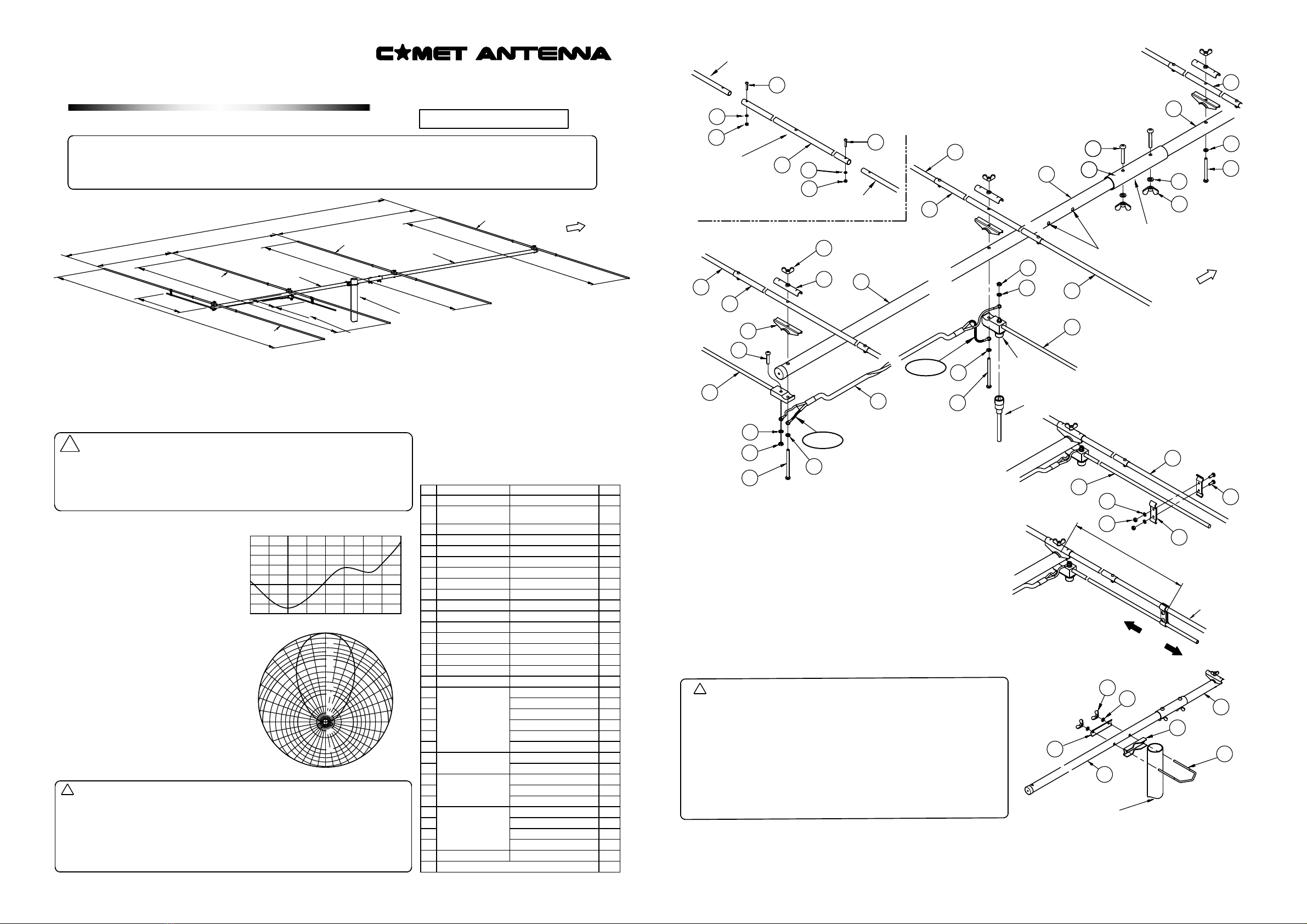
Main Beam
2nd Director
Boom A
1st Director
Boom B
Radiator
Reflector
Your Mast
or Pole
Short-Bracket
Standard Position
Short-Bracket
Standard Position
Check all parts are included,
according to the parts list.
【Features】
1. Compact and lightweight design for DX transmitting use
2. HB9CV extented 2 Element Beam Antenna with high gain
3. Heavy-duty with stainless steel screws
●
Precautions for assembling
Wearing a safety hat and a life line during installing on a roof top or any
high places is highly recommended.
Do not erect this antenna near any electrical power lines and/or street
lights.
●
【Specifications】
● Frequency : 50 – 53.5MHz
● Gain : 10.4 dBi
● F/B : 19dB or more
● Half-power angle : approx 54°
● Input Power : 200W(FM)
● Impedance : 50Ω
● V.SWR : 1.5 or less at 50 – 53.5MHz
● Connector : SO-239 (M-J) type
● Turning Radius : approx 2.22m
● Mounting Mast Diameter : φ25 – 62mm
● Max Wind Survival : 30m/sec
● Wind Load : approx 0.054m2
● Boom Length : approx 3.25m
● Length : approx 2.97m
● Weight : approx 2.1kg (antenna body)
SWR
1.8
1.5
1.4
1.3
1.2
1.1
1.050MHz 52MHz 54MHz
90゜
0゜
180゜
60゜
30゜
120゜
150゜
240゜
210゜
300゜
330゜
270゜
Directinal Pattern
8.0
10
6.0
4.0
3.0
2.0
1.0
15
20
20
10
●Precautions for Installation
Choose a safe place to erect this antenna, complying with the laws and
regulations in your country.
Be sure to tighten and waterproof all screws, nuts and bolts.
Do not erect this antenna near any overhead wires, steel towers, buildings
or any other obstacles.
●
●
【Parts List】
1
2
3
4
5
6
7
8
9
10
11
12
13
14
15
16
17
18
19
20
21
22
23
24
25
26
27
28
29
30
31
32
33
Parts Name Qty.
1
1
2
2
2
2
4
1
1
1
4
4
4
1
1
1
1
2
2
2
1
4
8
4
4
4
4
8
4
6
4
8
1
Boom A
Boom B
Element(A)
Element(B)
Element(C)
Element(D)
Center Element
Regulating Rod(1)
Regulating Rod(2)
Phase Line
Short-bracket
Element-holder A
Element-holder B
Backing plate
Fixing bracket
U-Bolt
Boom Joint
Pan-head Screw
Wing Nut
Hex. Nut
Spring washer
Self-fusing tape
*appearance and/or specification are subject to change.
φ25 × 1625 mm
φ25 × 1625 mm
(with a hole for U-Bolt)
φ9.5 × 1010 mm
φ9.5 × 1035 mm
φ9.5 × 1090 mm
φ9.5 × 1215 mm
φ11 × 600 mm
with SO-239 Connector
Rod without Connector
with terminal
aluminum
aluminum
aluminum
stainless
M6
Zinc Plating
M6×40
M5×70
M5×55
M5×25
M4×12
M3×15
for M5
for M6
for M5
for M4
for M3
for M6
for M5
for M4
for M3
preinstalled with
Regulating Rod(2)
4 preinstalled with
Regulating Rod
2 preinstalled with
Regulating Rod
Element(A),(B),(C)
and (D)
Center
Element
Element Assembly figure
【How to Assemble】
1.Assemble first/second directors, radiator and reflector with each two
elements(A, B, C, D)
First Director length : 2610mm / Second Director length : 2560mm
Radiator length : 2720mm / Reflector length : 2970mm
2.Assemble other parts, according to the below fig.
*Short-bracket on radiator and on reflector ; Assemble both in a same way.
Boom Assembly figure
Holes for U-Bolt
Main Beam
50Ω Coaxial Cable
(Optinal Accesory)
※Stretch the self-fusing tape two
times longer and wrap it to the joint
of connectors for waterproofing.
Phase line
Note :
Make sure to connect the
black-colored terminals
on both ends of Phase-line
to Boom.
Black
Black
【How to adjust】
1.Put your 50Ω coax cable into CA-52HB4 SO-239 Connector, and check SWR.
With a high SWR reading, you have to re-adjust this antenna
2.When adjusting center frequency, move a short-bracket on the radiator.
fo becomes lower when moving short-bracket inward. (see the right fig.)
If not SWR becomes lower, try to adjust a short-bracket on the reflector.
*Move the antenna to a different mounting location when SWR stays high.
3.Tighten each screw and bolt to lock the antenna into its newly
adjusted position.
*Use backing plate, brackets and/or U-bolts etc when mounting
this antenna to your mast etc.
!【Precautions for operating】
● Check if the Cable Connector fits into the Antenna Connector.
● Keep children away from this antenna, especially while transmitting.
● Stop the use of this antenna immediately if you see the slightest trouble.
● DO NOT use this antenna out of spec.
● DO NOT use this antenna without element or with extra element.
● Never attempt to perform modification by yourself.
● While lightening, DO NOT touch this antenna.
Remove the radio, antenna and/or cable etc from devices.
Also check SWR after lightening.
COMET CO.,LTD. 4-18-2, Tsuji, Minami-ku, Saitama City, Saitama-Pref 336-0026 JAPAN
TEL: +81-48-839-3131 FAX: +81-48-839-3136
URL http : //www.comet-ant.co.jp 4th edition.
Copyright (C) 2019 COMET CO.,LTD. All Rights Reserved.
Your Mast
or Pole
fo:Lower
fo:Higher
Tune
Changes in the Frequency
Approx 50kHz /cm
Center Frequency
adjustable range : 50.4 – 51.4MHz
Radiator
M-J
Connector
32
28
23
7
23
28
32
5
7
18
17
2
1
30
20
7
26
30 5
8
24
12 2
6
7
13
21
9
30
26
19 30
10
30
19
831
27 11
5
22
25 29
14
1
15
16
2
①,②boom alignment position
HB9CV type 4element Beam antenna
for 50~53.5MHz
stainless
18
17 29
25
Element(A),(B),(C)
and (D)
Short-Bracket
Standard Position
310
MODEL
C
A-52HB4