M2 2M9SSB/FM User manual

M2 Antenna Systems, Inc. 4402 N. Selland Ave. Fresno, CA 93722
Tel: (559) 432-8873 Fax: (559) 432-3059 Web: www.m2inc.com
©2015 M2 Antenna Systems Incorporated 06/25/15
Rev.03
Model .........................................2M9SSB/FM
Frequency Range (2M9SSB).....144 To 146 MHz
Frequency Range (2M9FM).......145 To 148 MHz
*Gain ..........................................14.1 dBi
Front to back ..............................20 dB Typical
Beamwidth ...............................E=35° H=38°
Feed type ...................................“T” Match
Feed Impedance. .......................50 Ohms Unbalanced
Maximum VSWR........................1.2:1 Typical
Input Connector..........................“N” Female
Power Handling ..........................2.5 kW
Boom Length / Dia......................14’ 6” / 1” To 3/4”
Maximum Element Length..........40-5/8”
Turning Radius: ..........................8’
Stacking Distance.......................9’ 6” High & 10’ Wide
Mast Size....................................1-1/2” to 2” Nom.
Wind area / Survival ...................1.2 Sq. Ft. / 100MPH
Weight / Ship Wt.........................5 Lbs. / 7 Lbs.
M2 Antenna Systems, Inc.
Model No: 2M9SSB/FM
FEATURES:
Up to the minute design using a state-of-the-art computer optimization program to deliver the most gain for boom length of any antenna on the
market. Each model’s performance is optimized for a specific mode and frequency range, with no compromises to achieve unneeded band-
width: the 2M9SSB covers 144-146 MHz and the 2M9FM covers 145-148 MHz. Where do you want to make yourself heard?
Both models are ideal building blocks for a small turning radius, high-gain stacked array. Two horizontally polarized, vertically stacked
2M9SSB’s yield the same gain (14.8 dBd) as M2’s 33 ft 2M5WL, but with about 1/2 the turning radius (8’ - great for QTH’s that won’t permit a long boom
Yagi). The 2M9FM can be stacked on a cross boom for the same gain increases, and the turning radius is still a very manageable 10 ft.
The heart of these antennas is a driven element module originally designed for maritime ATS satellite service. All connectors are O-ring
sealed to the CNC machined block. Internal connections are sealed with a space-age silicone gel with nearly 4 times the dielectric strength of air. The
balun connectors are triple sealed on the coax and nut-sealed at the block connectors. The type “N” feed connector uses a gold-plated, beryllium copper
center pin.
Elements are 6061-T6 3/16” solid rod with UV stabilized polyethylene Button insulators and stainless steel keepers. Thousands of these type ele-
ments are in amateur and commercial service with NO failures! Booms are constructed of 6063-T832 aluminum alloy tubing with close-tolerance
swaged joints. Other key electrical and mechanical components are CNC machined for accuracy and durability. All hardware is stainless steel except
the U-bolts. For uncompromising performance and long term electrical / mechanical integrity, the 2M9SSB and 2M9FM are unmatched.
SPECIFICATIONS:
*Subtract 2.14 from dBi for dBd

2M9SSB DIMENSION SHEET

2M9FM DIMENSION SHEET

1. Start by laying out the boom sections using the DIMENSION sheet as a guide. Use 8-32 X 1-1/4
screws and locknuts to join sections. Sections may be swaged to fit each other or use short
internal splice sections.
2. Lay out the elements by length and position as shown the DIMENSION sheet. Start with the
reflector (longest) element and push on a black button insulator to about 1/2” from center. Push the
element through the holes 1/2" from the rear of the boom and install the second button, snugging it
up into boom. DO NOT BOTHER WITH ACCURATELY CENTERING the element at this time and
DO NOT INSTALL the stainless steel SHAFT RETAINERS yet. This is easier to do after all the
elements are installed in the boom.
3. Install the 3/16” rod DRIVEN ELEMENT as you did the reflector. Then continue with the installation
of the DIRECTORS. Note that the Director Elements do not consistently diminish in length from
rear to front, so pay close attention to length and position.
4. Now begin centering the elements. Use a tape measure to EQUALIZE the amount the element
sticking out on each side of the boom. Once you have all the elements centered, sight down the
element tips from the rear comparing each side. Look for any obvious discrepancies and correct if
found.
5. NOTE: The SHAFT RETAINERS, used for securing the elements, should always be used for
permanent and long term antenna installations. For portable or temporary use, or whenever it is
anticipated that the antenna will be disassembled within a short time, the retainers may be left off.
The button insulators, normally a tight fit, hold the elements quite securely.
Begin installing the stainless shaft retainers. Use thumb and index finger to hold a Shaft Retainer
over end of the 3/8 x 3” push tube (Shaft Retainer dished into tube). Hold the element firmly and
2M9SSB/FM ASSEMBLY MANUAL

start the keeper onto the rod by applying pressure with the push tube. Push the Shaft Retainer
until up tight against the button insulator (Locking pliers, lightly clamped up against opposite button
insulator will help maintain center reference and keep you from pushing the first Shaft Retainer too
far). Repeat for the opposite side. Continue installing Shaft Retainers until all elements are locked
in place.
6. Mount the DRIVEN ELEMENT T-MATCH BLOCK to the underside of the boom using a single 8-32
X 1-1/4" screw and lockwasher. Orient the block with feed connector facing to center and balun
connectors facing to rear. Block orientation may be reversed if you wish feedline to exit from rear
of boom.
7. Coil the balun so it will not extend beyond the reflector when installed. Attach balun to the Block
and tighten the connectors gently using a 7/16" end wrench. A lot of torque is unnecessary.
Squeeze the balun coil across the middle until it is close to the boom and secure to boom with a
nylon cable tie. Tie should be snug but not crushing or kinking the coax.
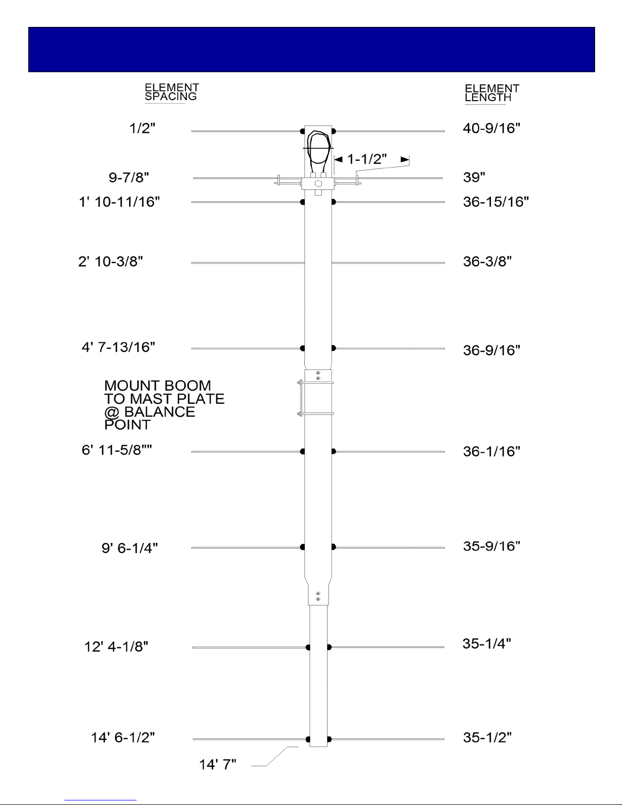
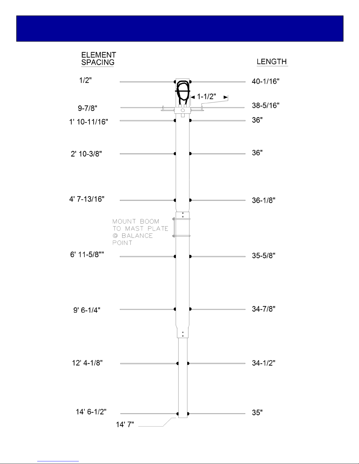
8. Install the 8-32 x 1/4” set screws (internal Allen head - tool supplied) into the SHORTING BARS.
Slide the bars onto the 3/16” rod driven element tips and then onto the Driven Element Block
Rods. Position the Shorting Bars as specified on the DIMENSION SHEET: the distance given is
between the outer edge of the Driven Element Block and the inner edge of the Shorting Bar. Align
the bars and rods with each other and tighten the setscrews.
9. The boom to mast plate is normally mounted at the balance point, about 70” from rear of boom.
Use two 1" U-bolts and the stainless nuts and lock washers provided. DO NOT OVER TIGHTEN.
2” U-bolts and cradles are provided for mounting the antenna, other sizes are available upon
request. Since the feed line represents significant weight it is best to have it attached and fastened
along the boom with cable ties before final mounting the plate.
THIS COMPLETES THE ANTENNA ASSEMBLY
MOUNTING AND STACKING INFORMATION
2M9SSB: FOR HORIZONTAL POLARIZATION, the 2M9SSB may be mounted to a metallic
vertical mast or a horizontal NON-METALLIC crossboom (no conductive material in element
plane). If mounted to a horizontal crossboom, route the feedline forward to the boom-to-mast plate,
loop down, and bring back to crossboom at least 6” beyond element tips. Two 2M9SSB antennas
are ideal for stacking, one above the other in horizontal polarity. Stacking distance (between H
planes) is 9’6”. Be sure both antennas are oriented so the driven element blocks are on the
SAME SIDE of the boom and NOT MIRROR IMAGE to each other. “E” plane stacking (side by
side, horizontal) distance is 10’.
2M9FM: FOR VERTICAL POLARIZATION, the 2M9FM SHOULD be mounted to a NON METALLIC
VERTICAL MAST (no conductive material in element plane) or a horizontal metallic crossboom.
If mounted to a NON METALLIC vertical mast, route the feed line forward to the boom-to-mast
plate, loop out at a right angle to the boom, and bring down THE FEEDLIINE to the mast at least 6
inches BELOW THE ELEMENT TIPS. Two 2M9FM antennas can be stacked side by side ,
vertically polarized on a METALIC horizontal crossboom. Stacking distance (between H planes)
is 9’6”. Be sure both antennas are oriented so the driven element blocks are on the SAME
SIDE of the boom and NOT MIRROR IMAGE to each other.
2M9SSB/FM ASSEMBLY MANUAL

DESCRIPTION QTY
BOOM SECTION, 1 X .058 X 60” SOE ............................2
BOOM SECTION, 3/4 X .049 X 60... ...............................1
ELEMENTS, 3/16 ROD x 2M9SSB Dimension Sheet......9
ELEMENTS, 3/16 ROD X 2M9FM Dimension Sheet .......9
DRIVEN ELEMENT BLOCK, T MATCH...........................1
BALUN, RG-6 1/2 WAVE ................. ...............................1
BOOM-TO-MAST PLATE, 0.125 X 3 X 4”........................1
U-BOLT AND CRADLE, 2’ ............... ...............................2
U-BOLT, 1”....................................... ...............................2
ASSEMBLY MANUAL ...................... ...............................1
IN HARDWARE BAG:
SHORTING BAR.............................. ...............................2
BUTTON INSULATORS................... ...............................18
SHAFT RETAINER, SS.................... ...............................18
NUT, 5/16-18 SS.............................. ...............................4
LOCKWASHER, 5/16 SS ................. ...............................4
NUT, 1/4-20 SS................................ ...............................4
LOCKWASHERS, 1/4 SS................. ...............................4
SETSCREW, 8-32 X 1/4, SS............ ...............................4
SCREW, 8-32 X 1-1/4 SS ................ ...............................5
LOCKNUT, 8-32 SS ......................... ...............................6
LOCKWASHER, #8 SS .................... ...............................1
CABLE TIE, NYLON ........................ ...............................3
ALLEN HEAD WRENCH, 5/64”........ ...............................1
PUSH TUBE, 3/8 X 3” ...................... ...............................1
M2ANTENNA SYSTEMS, INC.
4402 N. SELLAND AVE.
FRESNO, CA 93722
(559) 432-8873 FAX: 432-3059
2M9SSB/FM PARTS & HARDWARE
Table of contents
Other M2 Antenna manuals