M2 370CP38 User manual

M2 Antenna Systems, Inc. 4402 N. Selland Ave. Fresno, CA 93722
Tel: (559) 432-8873 Fax: (559) 432-3059 Web: www.m2inc.com
©2015 M2 Antenna Systems Incorporated 09/17/15
Rev.02
Model .........................................370CP38
Frequency Range.......................365 To 375 mHz
*Gain ..........................................17.4 dBi
Front to back ..............................24 dB Typical
Feed type ...................................Folded Dipole
Feed Impedance........................50 Ohms Unbalanced
Maximum VSWR........................1.6:1
Input Connector..........................“N” Female
Power Handling..........................1.5 kW
Boom Length / Dia......................186” / 1”, 1-1/4” & 1-1/2”
Maximum Element Length..........16”
Turning Radius:..........................108”
Stacking Distance.......................62” - 68”
Mast Size....................................2” Nom.
Wind area / Survival...................1.5 Sq. Ft. / 100MPH
Weight / Ship Wt.........................8 Lbs. / 10 Lbs.
M2 Antenna Systems, Inc.
Model No: 370CP38
FEATURES:
The 370CP38 is high performance circular polarized antenna with a remarkably clean pattern. The pattern is important in
order to match the antenna’s noise temperature with modern low noise preamps. This antenna is ideal for satellite work
but is also excellent for terrestrial uses like long haul tropo communications.
The CNC machined driven element module is O-ring sealed and weather tight for low maintenance and long-term
peak performance. Internal connected are encapsulated in a space-age silicone gel that seals out moisture and improves
power handling. The 3/16” 6061-T6 rod elements are centered on the boom to minimize interaction and maintain good
ellipticity. Insulators are UV stabilized and locked in place with stainless keepers. Rugged construction, uncompromising
performance for the boom length: that’s the M2370CP38!
SPECIFICATIONS:
*Subtract 2.14 from dBi for dBd

TOOL REQUIRED FOR ASSEMBLY: screwdriver, 11/32 nut driver or wrench, 7/16” and 1/2” socket or end
wrenches, measuring tape.
1. Assemble the boom using 8-32 screws and locknuts to join sections. ( SEE BOOM LAYOUT PAGE).
ASSEMBLING THE HORIZONTAL ELEMENTS
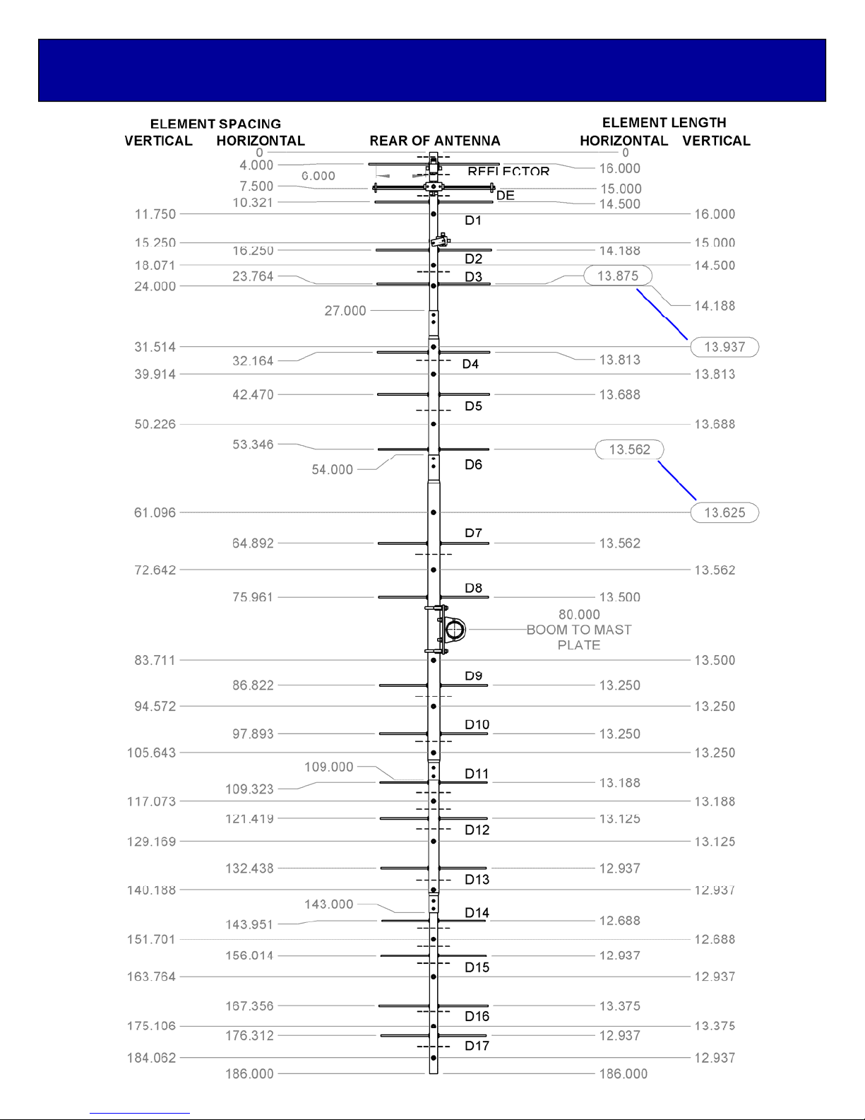
2. Lay out the elements by “Horizontal” length and position as shown the DIMENSION SHEET. Start with the
reflector (longest) element. Balance it on your finger to find rough center and push on a black button insulator
to about 1/2” off center. Push the element through the hole on the boom and install the second button,
snugging it up into boom. DO NOT BOTHER CENTERING the element at this time and DO NOT INSTALL
the stainless steel shaft retainers yet. It is easier to do it after all the horizontal elements are installed in the
boom.
3. Install the 3/16” rod DRIVEN ELEMENT as you did the reflector. Then continue with the installation of the
DIRECTORS. Note: the Director Elements do not consistently diminish in length from rear to front, so pay
close attention to length and position.
4. Now begin centering the elements. Use a tape measure to EQUALIZE the amount the element sticking out
on each side of the boom. Once you have all the elements centered, sight down the element tips from the
rear comparing each side. Look for any obvious discrepancies and correct if found.
5. Stainless steel SHAFT RETAINERS lock the elements in place. They should always be used for permanent
and long term antenna installations. For portable or temporary use, the button insulators are adequate for
holding the elements and the retainers may be left off.
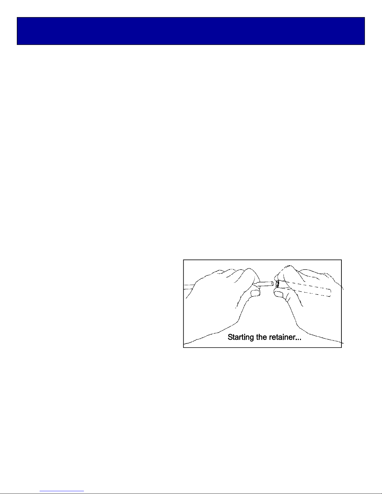
To install the stainless steel SHAFT RETAINERS, use thumb and forefinger to hold the retainer over the end
of the PUSH TUBE ( 3/8" x 3" tube, supplied in the kit), internal fingers on retainer dished into tube. HOLD
THE ELEMENT FIRMLY TO PREVENT IT FROM SLIDING OFF CENTER and press the retainer onto the
element end and continue until retainer butts on insulator button. Locking pliers, lightly clamped up against
opposite button insulator will help maintain center reference (if you push the first retainer too far, remove
element from boom, push retainer completely off
the element, and start over). Install another
retainer to the opposite side of the element.
Continue installing retainers until all elements
are secured.
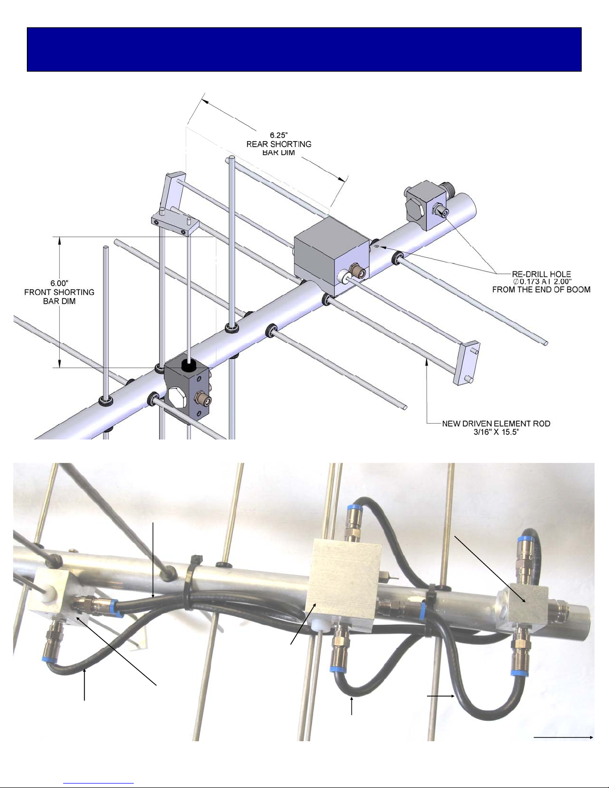
6. Mount the HORIZONTAL DRIVEN ELEMENT
ROD ASSEMBLY to the TOP of the boom using
a single 8-32 X 1-1/4" screw (SEE PICTURE).
7. Install the 8-32 x 1/4” set screws (internal Allen
head - tool supplied) into the SHORTING BARS.
Slide the bars onto the Driven Element Block
Rods and the 3/16" driven element rods.
Position the Shorting Bars as shown on
dimension sheet.
ASSEMBLING THE VERTICAL ELEMENTS
Note: The vertical element set is shifted forward on the boom by 1/4 wave lengths. This increases isolation
between element planes, improving circularity and ease of phasing / matching the two element sets.
8. Repeat steps #2 through #5 for the Vertical elements, using the Dimension Sheet as your guide to lengths
and spacing.
INSTALLATION OF THE VERTICAL DRIVEN ELEMENT BLOCK DETERMINES THE CIRCULARITY OF
THIS ANTENNA. THE ORIENTATION OF THE BLOCK FOR RHC - RIGHT HAND CIRCULARITY, IS
SHOWN ON THE DIMENSION SHEET.
9. Viewed from the rear of the boom (rearmost Reflector HORIZONTAL), the VERTICAL Driven Element Block
mounts to the LEFT hand side of the boom with the two Balun connectors oriented to the REAR. Secure with
8-32 x 1-1/4” screw. Install the Shorting Bars as in step #7.
370CP38 ASSEMBLY MANUAL

10. Before installing the Baluns and Matching / Phasing Harness, thread 3/8” SEAL NUTS fully onto all
connectors, with the black Neoprene face of the nuts facing out. Attach Baluns and Phasing lines to the
Driven Element Blocks and Junction Block as shown on the picture below. Tighten the connectors gently
using a 7/16" end wrench. Once the connectors are tight, back the Seal Nuts out and finger-tighten firmly up
against the face of the connectors (or tighten gently with 1/2” end wrench). A lot of torque is unnecessary.
Depending on model and polarity, the Vertical balun may loop around another element. This is normal. Form
balun coax until it is close to the boom and secure with a nylon cable tie. Also secure the other balun and the
matching / phasing harness coax with cable ties. Ties should be snug but not crushing or kinking the coax.
11. Use good quality coax and “N” connector for your feedline (see Installation Tips). Secure feed coax near
connector on Junction Block, to provide stress relief. Allow about 60” of coax to hang in a loop between the
rear end of the boom and the reattachment point (at least 12” beyond element tips) on the mast or
crossboom. Do not route feedline thru boom to mast plate as exiting antenna here will adversely affect
circular field.
12. The boom to mast plate is normally mounted to the boom at the balance point. Since the feed line represents
significant weight it is best to have it attached and fastened to the boom with cable ties before final mounting
the plate. Use two 1" U-bolts and the stainless nuts and lock washers provided. DO NOT OVER TIGHTEN.
2” U-bolts (and stainless steel nuts / lockwashers) are provided for mounting the antenna to your NON-
CONDUCTIVE mast or crossboom. Other size u-bolts and cradles are available upon request.
THIS COMPLETES THE ANTENNA ASSEMBLY.
INSTALLATION TIPS
1. The 370CP38 is a circular polarized antenna and creates a field in all planes or polarities. Performance
DETERIORATES SIGNIFICANTLY if it is mounted on a metal (conductive) mast or crossboom. A mast or
crossboom of any NON-CONDUCTIVE material must be used. Fiberglass is the prime choice for its strength
and weather resistance. Mount the antenna so that element tips are at least 12” from any conductive
material (mast, tower, feedline, etc.).
2. Recommended feedlines, in order of preference:
Andrews or Celwave 1/2” hardline
Times LMR-400 or Belden 8214
Try to keep the cable run to under 100 ft. to prevent excessive signal loss.
3. To maintain proper phasing when stacking two or more antennas, mount each with the same orientation of
Driven Element Blocks. DO NOT MOUNT IN MIRROR IMAGE. See the Specification Sheet for stacking
distances. For more detailed stacking information contact M2.
370CP38 ASSEMBLY MANUAL

370CP38 BOOM LAYOUT
REAR OF ANTENNA
FRONT OF ANTENNA

370CP38 DIMENSION SHEET

370CP38 BTM/BALUN/PHASE LINE DETAIL
REAR OF ANTENNA
JUNCTION BLOCK
HORIZONTAL
D.E.
VERTICAL
D.E.
BALUN
BALUN
RG-6 3/4
RG-6 1/4
NOTE:
INSTALLATION OF THE D.E. BLOCKS DETERMINES THE CIRCULARITY OF THIS ANTENNA. THE
ORIENTATION OF THE BLOCKS FOR RHC - RIGHT HAND CIRCULARITY, IS SHOWN BELOW &
ON THE DIMENSION SHEET.
FOR LHC - LEFT HAND CIRCULARITY, SIMPLY REVERSE ONLY ONE OF TWO D.E. BLOCKS TO
THE OPPISITE SIDE OF THE BOOM. DO NOT TO REVERSE THE DIRECTIONS OF THE BALUNS.

POLARITY SWITCH OPTION DETAILS
REAR OF ANTENNA
JUNCTION BLOCK
HORIZONTAL
D.E. (P.S.)
VERTICAL
D.E.
BALUN
BALUN
RG-6 3/4 RG-6 1/4

370CP38 VSWR

370CP38 PARTS & HARDWARE
DESCRIPTION ..............................................................................QTY
BOOM SECTION # 1, 1.0 X .058 X 30”.........................................1
BOOM SECTION # 2, 1.25 X .058 X 30” SOE..............................1
BOOM SECTION # 3, 1.50 X .058 X 55” SBE...............................1
BOOM SECTION # 4, 1.25 X .058 X 37” SOE..............................1
BOOM SECTION # 5, 1.0 X .058 X 45”.........................................1
ELEMENTS, 3/16 ROD x DIM SHEET..........................................38
DRIVEN ELEMENT ASSEMBLY...................................................2
JUNCTION BLOCK ASSEMBLY...................................................1
BALUN RG-6 X 13.5”.....................................................................2
PHASE LINE, RG-6 1/4(7”)1
PHASE LINE, RG-6 3/4 (20.75”)1
BOOM-TO-MAST PLATE, 4 X 6 X .188" (M2APT0022) ...............1
SHORTING BAR, 1/4” X 3/4” (M2ASB0080).................................4
U-BOLT & CRADLE, 2”..................................................................2
U-BOLT, 1.5"..................................................................................2
PENETROX / ZINC PASTE CUP ..................................................1
ASSEMBLY MANUAL....................................................................1
HARDWARE:
BUTTON INSULATORS................................................................76
SHAFT RETAINER, SS.................................................................76
NUT, 5/16-18 SS............................................................................8
LOCKWASHER, 5/16 SS...............................................................8
SCREW, 8-32 X 1-3/4 SS..............................................................4
SCREW, 8-32 X 1-1/2 SS..............................................................4
SCREW, 8-32 X 1-1/4 SS..............................................................3
LOCKNUT, 8-32 SS.......................................................................8
SETSCREW, 8-32 X 1/4, SS.........................................................8
CABLE TIE, 8” NYLON..................................................................4
SEAL NUTS, 3/8-32.......................................................................8
ALLEN HEAD WRENCH, 5/64”.....................................................1
PUSH TUBE, 3/8 X 3”....................................................................1
POLARITY SWITCH OPTION:
PS-370CM POLARITY SWITCH ASSEMBLY...............................1
DRIVEN ELEMENT ROD, 3/16” X 15.5.........................................1
SHAFT RETAINER, SS.................................................................4
M2ANTENNA SYSTEMS, INC.
4402 N. SELLAND AVE.
FRESNO, CA 93722
(559) 432-8873 FAX: 432-3059
Table of contents
Other M2 Antenna manuals
Popular Antenna manuals by other brands

NoiseKen
NoiseKen NKU07M32G instruction manual

LF Engineering
LF Engineering H-800 SKYMATCH quick start guide

ZCG
ZCG CT800 installation guide

Parsec Technologies
Parsec Technologies ST. BERNARD A installation instructions

ASL INTERCOM
ASL INTERCOM ANT04 product manual

Matsing
Matsing MS-MBA-2-L2 instruction manual