M2 2M HO LOOP User manual

M2 Antenna Systems, Inc. 4402 N. Selland Ave. Fresno, CA 93722
Tel: (559) 432-8873 Fax: (559) 432-3059 Web: www.m2inc.com
©2018 M2 Antenna Systems Incorporated 7/16/18
REV A
M2 Antenna Systems, Inc.
Model No: 2M HO LOOP
Model .........................................2M HO LOOP
Frequency Range.......................144 To 144.5 MHz
Gain, Typical @ 10 ft..................4 dBd @ 10 deg.
Gain, 2 STK @ 82” & 132”.........8 dBd @ 9 deg.
Polarity .......................................Horizontal Omni
Impedance .................................50 ohms, unbalanced
Power Handling..........................800W, 1.5 kW for Stack
Feed Connector………………….SO– 239
Mounting………………………….3/8-24
Vehicle Mounting height………...18” or more
Stacking Separation...................36” to 50”
Wind Area...................................0.025 sq. ft.
Weight……………………………..14 oz.
FEATURES:
For quick and easy communications up to 200 miles or more, the new 2M HO LOOP provides an omnidirectional, HORIZON-
TALLY polarized signal ideal for mobile and base operations on sideband and CW. Horizontal polarity permits a single HO loop to pick
up 4+dB of ground gain that verticals can't. As with most horizontally polarized antennas, performance improves dramatically with
height above ground. By stacking two HO LOOPS, another big gain jump occurs. HO LOOPS do not need a counterpoise, so mounting
options are simplified. Mounting 18” high, in the middle of a vehicle roof produces 2 dBd gain in a ball pattern upward for LEO satellite
and modest terrestrial operation.
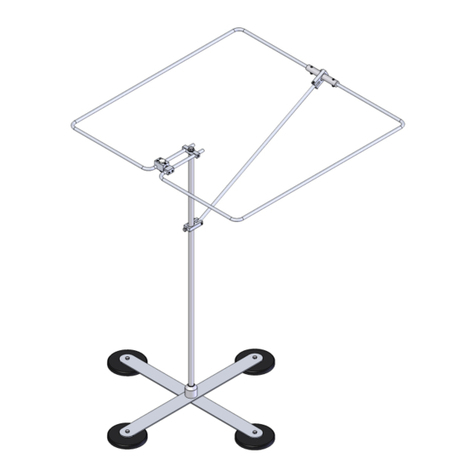
Physically, the 2M HO LOOP is a 11.25” square loop, fabricated from two 3/8” dia. aluminum tubes to minimize losses. The sealed
feed block provides weather protection with minimum wind drag. The heart of this unique design is the shorted stub matching to a 50
ohm coax feedline. Mounting is via a single 3/8" hole (standard mobile mounting hardware size).
For more performance, try the HO LOOP-STACK KIT: INCLUDES: phasing lines, “T” junction block, upper and lower 1/2 “ and 5/8”
mast sections. For easy base-station installation use the optional wall / mast mounting bracket and U-bolts. For a powerful mobile sig-
nal, stack and array of HO LOOPs on our optional “BIG FOOT”, mag-mount ( shown above). Use the optional 5” magnet and 18” mast
for single band mobile operation.
SPECIFICATIONS:
*Subtract 2.14 from dBi for dBd

1.Insert the 1/4-20 x 1/4" set screws a few threads into the two connector blocks. Use the 1/8" Allen
wrench provided. Insert the 1/4-20 x 1/4" set screws a few threads into the ends of the shorting bar.
2. Refer to the HO-LOOP ASSEMBLY SHEET and insert the tubes into the two connector blocks as
shown. Slide on the shorting bar, align the loops and GENTLY tighten the 1/4-20 x 1/4" set screw onto
the tubes. Slight bending of the tubes will ensure that all tubes are straight and square to each other.
Be sure the blocks are set to the starting ’A’ dimension. The ‘A’ dimensions controls the FREQUENCY.
3. Set the shorting bar to the ‘B’ dimension shown and tighten gently. When complete check match and
tighten . The ‘B’ dimension controls the MATCH
4. Once the loop is assembled either final tune it in its final position on your vehicle or if tower mounted,
simulate the mast size and other conditions to minimize final tuning in position.
4. That is about it. A 3/8-24 x 1" bolt and washer is provided to attach the HO LOOP to any standard
mobile mast or any M2 mast available as an option.
REMEMBER, HORIZONTALLY POLARIZED ANTENNAS ARE AFFECTED BY THE GROUND SO
THE HIGHER YOU AND GET YOUR HOOP LOOP THE BETTER. The ground can be your friend as
well providing as much as 6 dB additional ground gain at some angle above the horizon. That angle is
defined by the frequency and height above ground. At one wavelength, 80" at two meters, the typical
angle of maximum radiation will be about 14 degrees. At two wavelengths, the angle is 7 degrees and
at 4 wavelengths ( 27 ft.), the angle is 3.5 degrees. Net gain improves with height because the pattern
hits the ground at a more grazing angle giving up less energy to the ground.
In most mobile installations 10 to 11 feet is about the practical limit for most driving conditions. The HO
LOOP works at just 18" above a vehicle roof and contacts out 200 miles are quite common. However
you will find more people to talk to and longer if you can get the HO LOOP up at the 10 foot level.
POWER CONSIDERATIONS : 10 Watts into the HO LOOP will do well out to about 80 miles. 150
Watts gets you into that 200 mile category and 350 to 400 Watts get to the 300-400 and you will enjoy
much longer QSO's on a regular basis. From a hill top location 600-800 mile QSO's have been reported
several times. We hope you enjoy your new HO LOOP and please keep an ear out for those rare but
wonderful skip openings to other parts of the country!
Contact M2 for optional items available for your HO LOOP!
M2ANTENNA SYSTEMS, INC.
4402 N. Selland Ave.
Fresno, CA 93722
(559) 432-8873 Fax: 432-3059
2M HO LOOP ASSEMBLY MANUAL

2M HO LOOP ASSEMBLY MANUAL

2M HO LOOP STACK KIT
Mount both antennas with no phasing cables installed. Make
sure the feed connectors are facing each other and the larg-
er feed blocks are on the opposite side on each anten-
na. (2M and 222 only). Creating a 180°phase shift.
Connect your feedline to the top antenna and tune to reso-
nance (see tuning instructions).
Connect your feedline to the bottom antenna and tune to
resonance at the same frequency as the top antenna.
Connect the phasing lines and adjust both antennas in
equal dimensions to resonate the system (as needed).
Route your main feedline as shown, seal and water proof
your system appropriately.
It is much easier to tune HO loops using an antenna analyz-
er, since your initial tuning may be beyond the transmit
range of your radio. HO loops are sensitive to their sur-
roundings, so it is best to tune the antenna(s) in their final
position, whenever possible.

MOUNTING & OPTIONAL KITS
UNIVERSAL MAST
BRACKET KIT
(PT# FGMASTBRKTKIT)
SIDE MOUNT
OR
TOPMOUNT
BIG FOOT MAG
MOUNT
(PT# FGBIGFOOT)
HO LOOP MAG
KIT
(PT# FGHOMAGKIT)

4402 N. Selland Ave, Fresno CA 93722 (559) 432-8873 FAX (559) 432-3059
HO LOOP, STANDARD PARTS LIST
DESCRIPTION QTY
H.O. LOOP HALF 2
H.O. FEED ASSEMBLY WITH SO-239 CONN 1
H.O. SHORTING BAR 1
SET SCREW, 1/4-20 X 1/4 S.S. 6
ALLENWRENCH,1/8 1
BOLT, 3/8-24 X 1” SS 1
FLATWASHER,3/8SS 1
ASSEMBLYMANUAL 1
OPTIONAL HO LOOP-STACK KIT (# FGSTACKKIT2M)
DESCRIPTION QTY
COAXIAL CABLE RG-59 X 33” @ 3/4 W/L 1
COAXIAL CABLE RG-59 X 11” @ 1/4 W/L 1
LOOP MAST, 5/8 X 18" 1
LOOP MAST 1/2 X 32" 1
ASSEMBLY MANUAL 1
HARDWARE BAG
JUNCTION BLOCK 1
STUD, 3/8 X 24 X 1-1/2" 1
3/8 FLAT WASHER 4
CABLETIES 2
OPTIONAL MAG-MOUNT KIT (# FGHOMAGKIT)
DESCRIPTION QTY
5”MAGNET 1
MYLARCOVER 1
MAST,5/8X16” 1
BOLT, 3/8-24 X 1/2 S.S. 1
FLATWASHER,3/8S.S. 2
CABLETIES 2
OPTIONAL MAST BRACKET KIT (# FGMASTBRKTKIT)
DESCRIPTION QTY
HO LOOP MAST BRACKET (M2APT0064) 1
UNI-CRADLE(M2AMC0076) 2
U-BOLT,2”SS 2
BOLT, 3/8-24 X 1.5 SS 1
LOCKNUT, 3/8-24 SS 1
LOCKWASHER,1/4SS 4
NUT,1/4-20SS 4
2M HO LOOP PARTS & HARDWARE
Other manuals for 2M HO LOOP
1
Table of contents
Other M2 Antenna manuals