M2 AAD User manual

01.12.04 EN
USER´S GUIDE
m2 AAD

2
CONTENT
1. Warning ............................................................................. page 3
2. Introduction ....................................................................... page 4
3. Function ........................................................................... page 5
3.1 Construction and principal ................................................. page 5
3.2 Individual device parts ....................................................... page 5
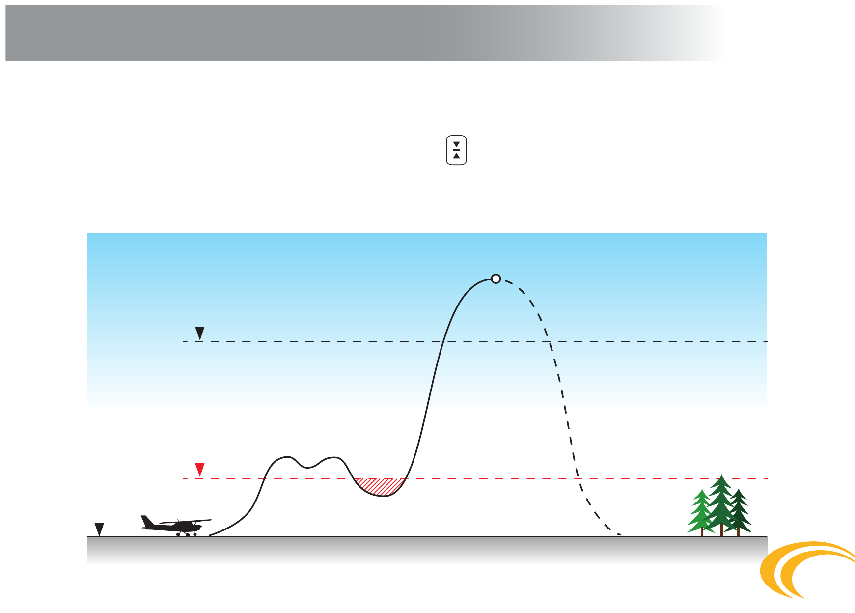
3.3 Function principle............................................................... page 6
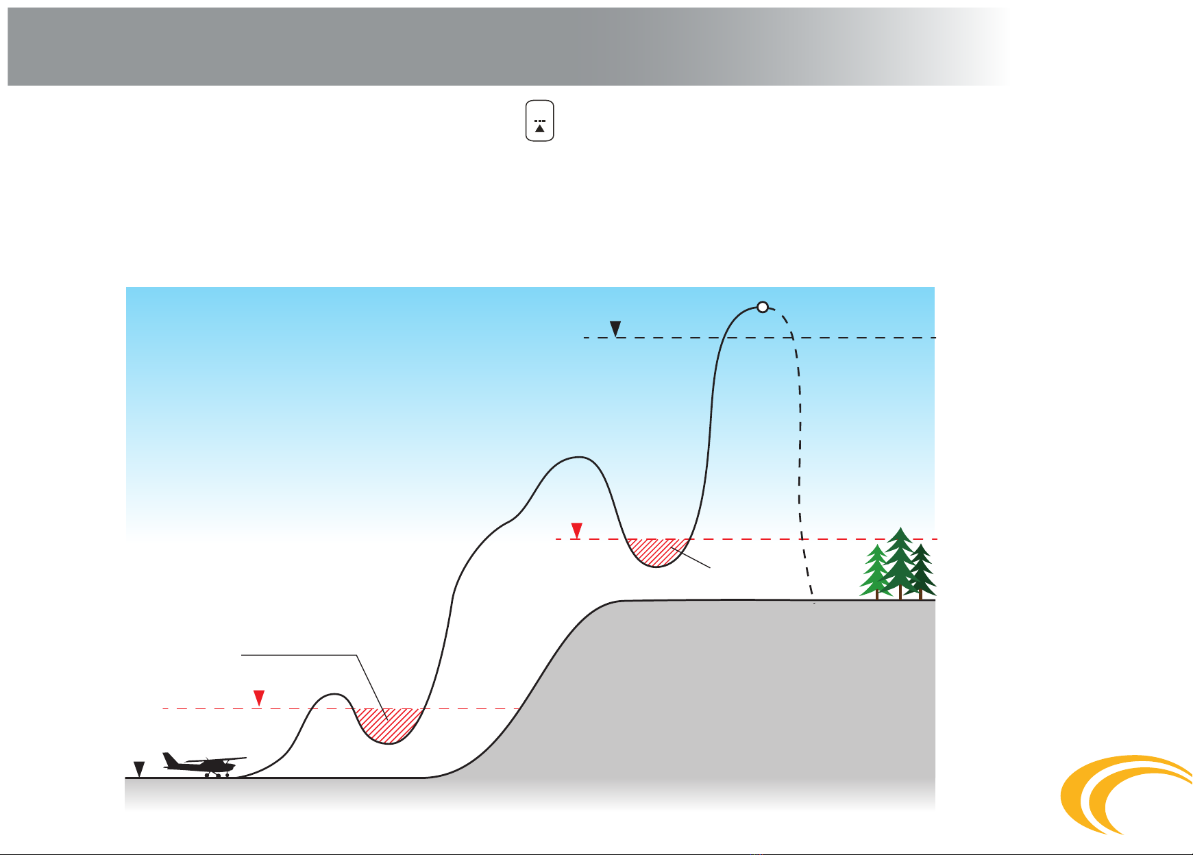
3.4 Activation zone................................................................... page 10
3.5 Altitude lock ....................................................................... page 11
3.6 Limited speed .................................................................... page 12
4. Models................................................................................ page 13
4.1 Student............................................................................... page 13
4.2 Expert (Swoop)................................................................... page 13
4.3 Tandem .............................................................................. page 13
5. Installation ......................................................................... page 14
6. Control ............................................................................... page 17
6.1 Switching the device on ..................................................... page 17
6.2 Switching the device o ..................................................... page 18
6.3 Resetting the height of landing location ............................ page 18
6.4
Information in the device memory calibrated in meters (m)
... page 20
6.5 Information in the device memory calibrated in feet (ft).... page 22
6.6 Switching on Schema – meter version ............................... page 24
6.7 Switching o Schema – meter version ............................... page 25
6.8 Switching on Schema – feet version................................... page 26
6.9 Switching o Schema – feet version................................... page 27
7. Maintenance ...................................................................... page 28
7.1 m2release unit (cutter) replacement ................................. page 28
7.2 Filter replacement .............................................................. page 29
7.2.1 Procedure when the m2is used under water ..................... page 29
7.2.2 Procedure during the lter incorrect function..................... page 29
7.2.3 Waste disposal ................................................................... page 29
7.3 Battery ............................................................................... page 30
8. Ensuring closing loop to the washer .................................. page 31
9. Error reports ....................................................................... page 32
10. Technical data..................................................................... page 33
11. Warranty............................................................................. page 34

3
1. Warning
Skydiving is a dangerous activity which can result in serious or even fatal injury.
Training and experience are required in order to reduce such risk. Using the m2safety device during skydiving can signicantly reduce
the risks. Never solely rely on the m2, since it is not the primary tool for opening of your parachute. Remember the m2is an electronic
device and, just like other equipment, it can fail. Read the instruction manual thoroughly prior to using the device. The device is not
designed for PARAGLIDING, PARASCENDING, PARASAILING, or BASE JUMPING. The failure-free function of the m2cannot ensure the
correct function of the parachute system, i.e. the harness with the container, the reserve parachute, and the accessories.
Warning for users !!!!
Each part and component of the m2is thoroughly checked several times during production. Despite all due care applied during
production, assembly and appropriate use, the m2can fail!!!
The m2device is responsible solely for cutting the closing loop of the reserve parachute!!!
The m2is not responsible for the correct function of the system with container, reserve parachute, and other accessories.
1.1
1.2

4
2. Introduction
The m2safety device provides automatic cutting of the closing loop of the reserve parachute in cases where the safety of the skydiver is
in danger. It is constructed and manufactured based on the latest skydiving research. Its function fully complies with the requirements
of current skydiving. Professional design engineers that participated in its development are also excellent skydivers.
The device is available in EXPERT, STUDENT, or TANDEM models. Upon activation, the m2’s operation is fully automatically. The main
features of the m2are its solid structure, exible cables, the possibility of being submerged under water during swooping, a lifetime for
the device of 15 years or up to 15,000 dives, simple operation, acceptable price, and quality service.
The device stores a ight record during active use. The metal parts are made from stainless steel or aluminum alloy.

5
3. Function
Construction and principal
The m2is constructed in order to comply with the requirements for resistance and correct function in all situations. It operates with
minimum requirements for energy consumption, which enables it to retain a sucient energy source capacity for its entire service life
without the necessity of battery replacement.
Individual device parts
The m2is comprised of the processing unit – the device body with battery, processor, electronic circuits, and pressure sensor. The con-
trol unit with multifunction display and control button is connected to the device body by means of a cable. The cutter is connected to
the body of the device by means of a connector that is a replaceable part of the device.
Function principal
The m2device is an electronic safety device, operating on the principal of pressure sensing.
The pressure sensor monitors the actual atmospheric pressure 8x per second during free fall; the received information is evaluated
by means of software and recalculated to the real falling speed and actual height. Upon exceeding the activation limits preset for the
individual Expert, Student or Tandem versions, the m2device is able to use the cutter to cut the closing loop on the reserve parachute
and initiate its opening. The device is activated upon exceeding the altitudes and speeds specied.
The device is responsible solely for cutter activation as per specied limits, and cutting the closing loop of the reserve parachute.
It is not responsible for the correct and full function of the whole harness system with the container, reserve parachute, and other
accessories!!!
3.1
3.2
3.3
3.3.1
3.3.2

Ground
zero
+40m / + 130ft
Restricted area
+450m / + 1475ft
6
3. Function
The m2function for landing at a dierent altitude above sea level than the altitude the aircraft takes o from
Only three options can occur in regard to the skydiver´s landing:
Landing location at the same elevation as the take-o location
in such a case, the m2device requires for the aircraft to ascend up to at least 40m; it is further necessary, in order to provide
problem-free functioning and start the detection capability, to remain above this altitude until the skydiver´s dive. The alti-
tude lock is at either 450m or 900m, depending on the version.
3.3.3
a)

7
Ground
zero
+40m / + 130ft
+40m / + 130ft
Restricted area
Restricted area
+450m / + 1475ft
3. Function
Landing location higher than the take-o location
The m2device must be preset to the positive value for the elevation dierence between the take-o and landing location altitudes. The
altitude lock in such a case depends on the landing location, i.e. as per version 450m or 900m, plus the specied altitude dierence. In
order to provide problem-free functioning and take-o detection ability in such a case, the m2device requires an ascent up to at least
40m above the take-o location and, upon reaching and exceeding this preset altitude of +40m, remaining above this altitude level
until the skydiver´s jump. Upon landing with the preset altitude, the device automatically switches o. Switch on the device prior to the
next dive, i.e. at the take-o altitude of the aircraft. You will be provided with failure free calibration and functioning of the m2device.
b)

Ground
zero
+40m / + 130ft
+40m / + 130ft
Restricted area
+450m / + 1475ft
90 seconds
8
3. Function
Landing location lower than the take-o location
The m2device must be preset to the negative value for the elevation dierence between the take-o and the landing location altitude. The
altitude lock in such cases depends on the landing location, i.e. as per version 450m or 900m, minus the specied altitude dierence. In or-
der to provide problem free functioning and take-o detection ability in such cases, the m2device requires an ascent up to at least 40m abo-
ve the take-o location and, upon reaching the preset altitude of +40m, remaining above this altitude level for at least 90 seconds. After 90
seconds, it is possible to even descend lower than the take-o altitude; nevertheless, descending more than -40m below the preset landing
altitude is strongly warned against. Upon landing with the preset altitude, the device will automatically switch o. Switch on the device
prior to the next jump, i.e. at the take-o altitude of the aircraft. This will provide failure free calibration and functioning of the m2device.
c)

9
3. Function
Should you accidentally land in a location 30m higher or lower than the preset landing elevation, switch the device o after
landing and turn it on just before the next dive. The device must always be switched o during transport.
Altitude protection zone of the m2device – “! Important for the aircraft pilot !”
The altitude protection zone of the m2device consists of the rst 40m of elevation above the aircraft take-o location. It is necessary
to exceed the 40m as fast as possible at a steady ascent. At 40m, the m2device detects the aircraft take-o and switches from “stand-
-by” mode to “y” mode. Upon exceeding the 40m protection zone, the device must not drop under this altitude (40m) until the dive
is completed. The only exceptions are in those cases when the skydiver’s landing zone is located at a dierent altitude than the
aircraft take-o location. For such cases, carefully read“the m2function for landing at dierent altitudes above sea level than the
aircraft take-o altitude” chapter, where the specied m2functions are detailed and illustrated with diagrams.
Function of the m2during use in pressurized aircraft
The m2device can be used in pressurized aircraft providing the conditions below are observed:
The ambient atmospheric pressure (outside the aircraft) must be maintained inside the aircraft up to 450m above the aircraft take-o
location for the Expert and Student device versions and 900m for the Tandem version. At the specied altitudes, the device will be un-
locked, which will be indicated by the disappearance of the centre line on the control unit. Once the altitude lock unlocks, the aircraft
can be pressurized.
The aircraft must not be pressurized to a pressure higher than the ambient atmospheric pressure adequate for an altitude of 450m or
900m. If there are devices present in the aircraft with preset altitude locks for 450m and 900m, the pilot must pressurize the aircraft for
ambient atmospheric pressure at 900m.
If the specied limits are not observed, the device may fail.
d)
3.3.4
3.3.5
a)
b)
c)

10
3.4 Activation zone
AZgz – Activation zone above ground zero;
EXPERT 270m (885ft) to 100m (330ft)
STUDENT 330m (1085ft) to 60m (200ft)
TANDEM 610m (2000ft) to 100m (330ft)
BAgz – Beginning of activation zone above ground zero;
EXPERT 270m (885ft)
STUDENT 330m (1085ft)
TANDEM 610m (2000ft)

11
3.5 Altitude lock
UAgz – The altitude for unlocking during ascent (of plane) above ground zero;
EXPERT 450m (1475ft)
STUDENT 450m (1475ft)
TANDEM 900m (2950ft)
LAgz – The altitude for locking during descent (on parachute) above ground zero;
EXPERT 100m (330ft)
STUDENT 60m (200ft)
TANDEM 100m (330ft)
LAgz is at the same time the bottom limit – the end of activation zone.

12
3.6 Limited speed
LSgz – Limited speed above ground zero in AZgz;
EXPERT 35m/s (78mph) at 270m (885ft)
STUDENT 20m/s (45mph) at 330m (1085ft)
TANDEM 35m/s (78mph) at 610m (2000ft)

13
4. Models
EXPERT
Activation occurs if the altitude above the landing area is below 270m (885 ft) and the descent speed is over 35 m/s-1 (78 mph). The
altitude lock is 450m (1475 ft).
Activation will not occur under an altitude of 100m (330 ft).
STUDENT
Activation occurs if the altitude above the landing area is below 330m (1085 ft) and the descent speed is over 20 m/s-1 (45 mph). The
altitude lock is 450m (1475 ft).
Activation will not occur under an altitude of 60 m (200 ft).
TANDEM
Activation occurs if the altitude above the landing area is below 610m (2000 ft) and the descent speed is over 35 m/s-1 (78 mph). The
altitude lock is 900m (2950 ft).
Activation will not occur under an altitude of 100 m (330 ft).
4.1
4.2
4.3

14
5. Installation
Installation of AAD
m2
into containers made by various manufacturers can be performed solely by those persons with senior-master ri-
gger certication, or a holder of a comparable equivalent according to the legislation of the individual countries where the
m2
is installed.
The m2must be installed only into the original set supplied by MarS and installed directly into the container by the harness manufactu-
rer or, potentially, by an authorized rigger. The rigger must always adhere to compliance with the manual issued by the manufacturer
of the container during installation of the cutter, cable lines, the m2body pouch, and the control units.
Alternatively, the safety device can be installed into sets of other manufacturers if the following conditions are met:
Prior to installation, check the device for any mechanical damage of the individual parts, including the cables, and ensure that the co-
nnector of the cutter is suciently inserted into the device body and secured with the retaining screw. Then switch the device on to
check that everything is correctly installed, and switch it o again.
The
m2
device body must be inserted into the pocket sewn into the
bottom part of the reserve parachute in a manner that ensures the cable
outlets from the
m2
body are as close to the bottom part of the container
as possible. Proper installation reduces cable strain due to the pressure
from the reserve parachute being in a close–packed container.
The cables of the m2safety device should be placed in the sequence
below:
The thin cable of the cutter is always rst. If the set for placing the m2
is sewn in such way that upon inserting the m2device body into the po-
cket, the thin cable of the cutter is lower than the thick cable, wind the
cable clockwise from the front view (if it is sewn higher, wind the cable
counter-clockwise). The wound cable must be placed in the prepared
area in such a way that ensures the cable lies as close to the bottom of
the container as possible, and in the area xed with Velcro strips.
5.1
5.2
5.3
•
•
•
a)

15
5. Installation
The thick cable of the control unit is always second and must be
placed on the wound thin cable. If the m2device body is placed in
such a way that the thick cable is higher than the thin cable, wind
the cable counter-clockwise from the front view. If the set and devi-
ce are placed in the opposite direction, then it is the reverse.
“Adhere to minimum radius for cable winding r = 25mm!
Bending a strong cable can result in its damage and subsequent
defective function of the m2!”
Both folded cables are secured with the Velcro strap.
Avoid sharp bends, knots, and mutual entanglement of cable while
placing cables.
“Adhere to minimum radius for cable winding r = 25mm!
Bending a strong cable can result in its damage and subsequent
defective function of the m2!”
Avoid pulling on the cables, particularly the control unit and the
cutter.
b)
c)
Cable of Control Unit
Cable of Cutter

16
5. Installation
The cutter and the control unit location must comply with the harness manufacturer’s manual so that in both cases at least mi-
nimum cable spacing is ensured. Cable spacing reduces the probability of the device being damaged after packing and during
common use.
Carefully study the container manufacturer’s manual prior to general installation.
Cables must not be placed in the pocket for the device
body and, at the risk of cable damage, must not be even
partially under the device body.
d)
e)
Elastic pouch with Processing Unit
Control Unit

17
6. Control
Switching the unit “on”
Quickly press the control button (2) on the control unit body (1). Upon the icon being dis-
played (3) immediately press the control button a second time; the icon will be displayed;
immediately press the button a third time; when the icon is displayed, immediately press
the button for the fourth time. The ashing icon will be displayed, which indicates the au-
to-test and pressure calibration are in progress. Upon completion, the icon will be shown
on the display (3).The device is now on and preset to zero altitude – GROUND ZERO. If you fail
to switch o the device, it will automatically switch o after 14 hours.
The button only requires a short press - click. Pressing must occur when the icon appears
on the display. If this switching frequency has not been properly completed, the device will
return to the OFF mode. The sequence must be repeated in order to start the device.
6.1
1
2
3

18
6. Control
Switching the unit o
Quickly press the control button (2) on the control unit body (1). Upon the icon being displayed (3) immediately press the button
for a second time; the icon will be displayed; immediately press the button for a third time; when the icon is displayed, press
the button for the fourth time. No icon will be displayed. The device is now o. If the switching-o sequence has not been completed,
device will remain in ON mode.
Resetting the altitude of the landing location
If the landing location is higher or lower than the take-o location, the landing area altitude must be reset. The m2enables the landing
location altitude to be reset within a range of +/- 990m (+/- 2990ft) in steps of 10m (10ft).
Higher located landing location
If the landing location is higher than the location where the device is activated and calibrated, it is necessary to reset the device for the
altitude dierence in advance. The m2allows for upward adjustments between +10 to +990 m (+10 to +2990 ft).
Example of procedure:
The location of device activation and calibration before diving is at an altitude of 450m above sea level. The planned lan-
ding area after diving is at an altitude of 700m above sea level. The elevation dierence is 700 – 450 = plus 250 meters.
Procedure: Switch the device o.
Quickly press the control button (2) on the control unit body (1). Upon the icon being displayed (3) immediately
press the button for a second time, the icon will be displayed; immediately press the button for a third time, the
icon will be displayed; after a short time, the . icon will be displayed; Immediately press the button for the
fourth time and the digits 0,1,2 ….,8,9 will sequentially show up on the display. Pressing the button upon digit 2 being
displayed will preset 200m. Then the digits 0,1,2 ….,8,9 will again be displayed.
6.2
6.3
6.3.1
Higher located
landing area

19
6. Control
Pressing the button upon digit 5 being on the display will add a further 50m. The display will show 0. Press the button and the setting
is conrmed. The display will automatically sequentially show the icons “-“ “2“ “5“ “0“ “-“ (four digits in the feet version) for your veri-
cation and the device will complete the auto-test and calibration – ashing icon . It will then display the icon, notifying that
the device is now preset for the higher landing altitude. If the height presetting sequence is not properly completed, the device will
go back into the OFF mode.
Lower located landing location
If the landing location is lower than the location where the device is activated and calibrated, the device must be reset for the altitude
dierence in advance. The m2allows for upwards adjustments between -10 to -990m (-10 to -2990 ft).
Example of procedure:
The location of the device activation and calibration before diving is at an altitude of 700m above sea level. The planned landing area
after diving is at an altitude of 450m above sea level. The elevation dierence is 450 – 700 = minus 250 meters.
Quickly press the control button (2) on the control unit body (1). Upon the icon being displayed (3) immediately
press for a second time, the icon will be displayed; immediately press the button for a third time, the icon
will be displayed, after a short time, the icon will be displayed. Immediately press the button for the fourth time
and the digits 0,1,2 ….,8,9 will sequentially be displayed. Pressing the button upon digit 2 being displayed will preset
-200m. then the digits 0,1,2 ….,8,9 will be displayed again. Pressing the button upon digit 5 being displayed will add a
further -50m. The display will show 0. Press the button and the setting is conrmed. The display will automatically and
sequentially show the digits “-“ “2“ “5“ “0“ “-“ (four digits in the feet version) for your verication and the device will
complete the auto-test and calibration – ashing icon . It will then display the icon, notifying that the device
is now preset for the lower landing level. If the height presetting sequence is not properly completed, the device will
go back into the OFF mode.
6.3.2
Lower located
landing area

20
6. Control
Information in the device memory calibrated in meters (m)
Display description
The m2retains information which is available to the user upon following the steps below. The following information can be found in the
m2memory.
Opening altitude of the last dive (4 digits = 0000 to 9999m);
Total number of dives during the device’s operation (5 digits = 0-30000 dives);
Landing altitude adjustment (3 digits = 000 to 999m);
Remaining battery capacity in % (2 digits = 0 to 99%);
Device serial number (6 digits = XXXXXX);
Device conguration and rmware version (6 digits = VUFFFF);
Year and month of manufacture (6 digits = YYYYMM; Y = year, M = month);
“Gravity index” of the last dive (3 digits = 0–99.9%);
The “gravity index” is the maximum speed of the last dive expressed in percentage, while 100% = the speed limit when
the cutter will be activated under BAgz (minimum set altitude above ground zero).
Pressure in0.1 hPa (5 digits = XXXXX)
6.4
6.4.1
V= version
„1“ - expert
„2“ - student
„3“ - tandem
U= A/F
„A“ – device calibrated in meters
„F“ – device calibrated in feet
FFFF = rmware version
Other manuals for AAD
1
Table of contents
Other M2 Safety Equipment manuals
Popular Safety Equipment manuals by other brands

4EVAC
4EVAC Compact 500 quick guide

Grace Industries
Grace Industries SuperCELL SC500-H-IC User information

Dali Wireless
Dali Wireless Matrix PS Installation & commissioning guide

Thiele
Thiele TWN 0827/1 Mounting instructions

Reliance
Reliance 4810 Instructions for use

Dräger
Dräger Bodyguard 1500 Instructions for use