M2 AAD User manual

03.13.05 EN
USER´S GUIDE
m2 AAD

2
CONTENT
Warning .................................................................................... 2
1. Introduction .................................................................................... 4
2. Construction .................................................................................... 5
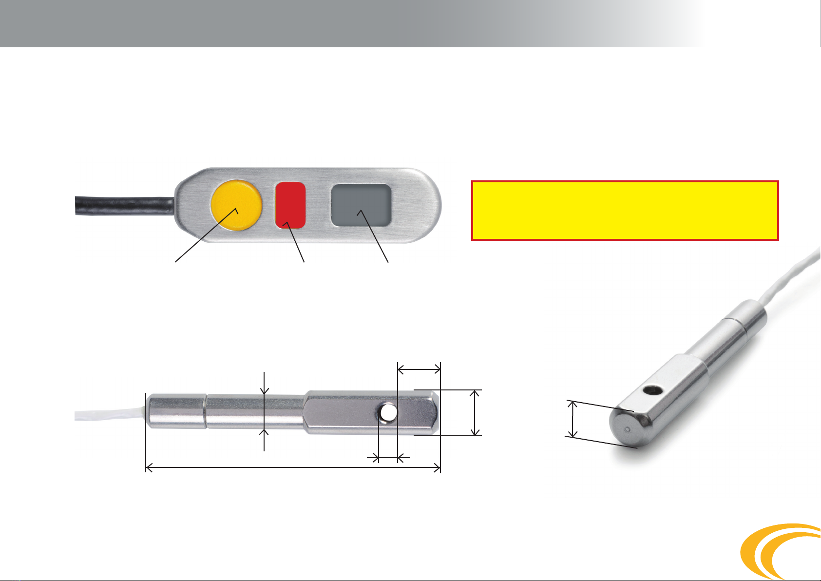
2.1 Individual Device Parts .......................................................... 5
2.2.1 Processing Unit ........................................................... 5
2.2.2 Control Unit ................................................................ 6
2.2.3 Cutter .......................................................................... 6
3. Function .................................................................................... 7
3.1 Function Principal .................................................................. 7
3.2 Functional Modes .................................................................. 7
3.2.1 STANDARD-mode ....................................................... 8
3.2.2 UP-mode .................................................................... 9
3.2.3 DOWN-mode............................................................... 10
3.2.4 X-mode ....................................................................... 11
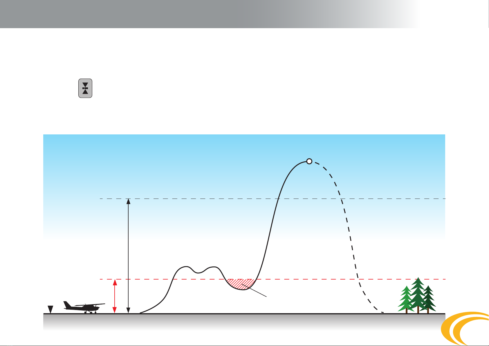
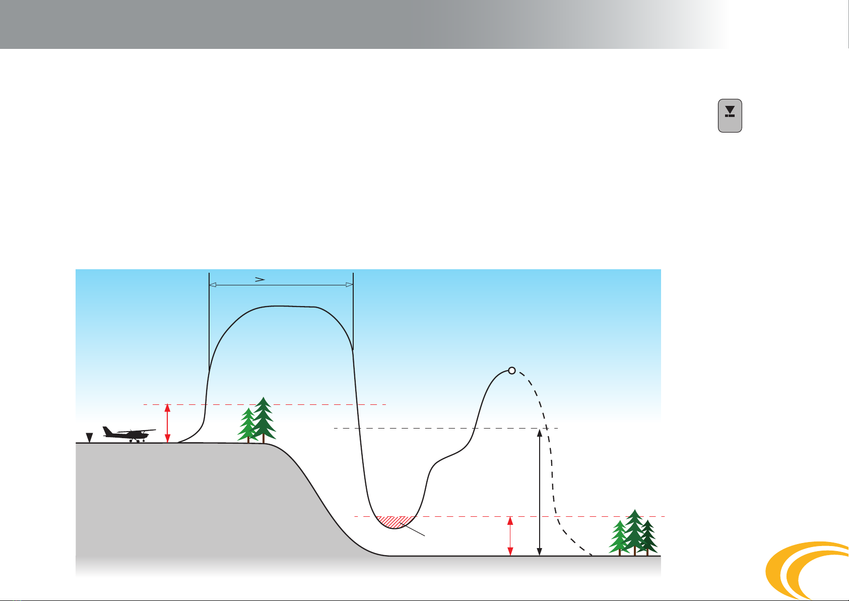
3.3 Altitude safety zone of the m2device ................................... 11
3.4 Function of m2at use in a pressurized aircraft ...................... 12
3.5 Altitude lock .......................................................................... 12
3.6 Landing in water ................................................................... 12
4. Safety Device Versions ...................................................................... 13
4.1 m2EXPERT ............................................................................ 13
4.2 m2STUDENT ......................................................................... 13
4.3 m2TANDEM .......................................................................... 14
4.4 m2SPEED .............................................................................. 14
5. Installation .................................................................................... 16
6. Control .................................................................................... 19
6.1 Control Principals ................................................................... 19
6.2 Switching device toSTANDARD-mode ................................... 19
6.3 Switching device o .............................................................. 20
6.4 Switching device toUP-mode ................................................ 20
6.5 Switching device toDOWN-mode .......................................... 21
6.6 Switching device toX-mode .................................................. 22
6.7 Information in the device memory - MENU ........................... 22
6.7.1 MENU display description ........................................... 22
6.7.2 Sequence to display MENU ......................................... 24
6.8 QuickCard switch-on sequence .............................................. 25
6.9 QuickCard switch-o sequence .............................................. 26
7. Maintenance .................................................................................... 27
7.1 Cutter Replacement ............................................................... 27
7.2 Filter Replacement ................................................................ 28
7.3 Battery .................................................................................. 28
7.4 Yearly Inspection ................................................................... 29
8. Securing closing loop in washer ....................................................... 30
9. Error Reports ................................................................................... 31
10. Technical Data .................................................................................. 32
10.1 Basic Technical Data ............................................................... 32
10.2 Total Lifetime of m2and Batteries ........................................ 32
10.3 Cutter Lifetime ...................................................................... 32
11. Important Principles ........................................................................ 33
12. Warranty .................................................................................... 34
13. X-ray Card .................................................................................... 35
14. Disclaimer ................................................................................... 36

3
Warning
Skydiving is a dangerous activity which can result in serious or even fatal injury.
Trainingandexperiencearerequiredinordertoreducesuchrisk. Usingthem2safety
device during skydiving can signicantly reduce the risks. Never solely rely on the
m2, since it is not the primary tool for opening of your parachute. Remember the m2
is an electronic device and, just like other equipment, it can fail. In the case of some
collisions, the m2may cause death. Read the instruction manual thoroughly prior
to using the device. The device is not designed for PARAGLIDING, PARASCENDING,
PARASAILING, or BASE JUMPING. The failure-free function of the m2cannot ensure
the correct function of the parachute system, i.e. the harness with the container,
the reserve parachute, and the accessories. The m2device is only responsible for
cutting a closing loop of a reserve parachute which is properly pulled through the
cutter!!!

4
1. Introduction
Thank you for buying the AAD m2, and we hope you will never nd yourself in a situation where you need it. Simply switch the m2device on
in the morning prior to the rst jump and it will guard your safety without any further bother.
The Automatic Activation Device„AAD“ is an automatic electronic safety device. The m2device continuously checks that the skydiver is not too
close to the ground without an open and functional parachute. It detects a skydiver’s falling speed and altitude. If the m2assesses the situation
as hazardous for the skydiver, the cutter automatically cuts the closing loop of the reserve parachute, which starts the process of opening the
reserve parachute. It is designed and manufactured based on the latest ndings focused on sports skydiving, and its function fully meets the
demands of the current skydiving sport.
Professional designers, who are also excellent skydivers, have contributed to its development. The device is available in m2EXPERT,
m2STUDENT, m2TANDEM andm2SPEED versions. Upon switching on the m2it works fully automatically, without user intervention.
The m2’s main advantages are:
• ultralowpowerdesign–noneedforbatteryreplacementthroughoutitslifetime
• 15-yearlifetimewithoutservicingrequiredbythemanufacturer
• compactsmoothroundedmetalconstruction
• minimalthicknessofthebody,controlunit,aswellasthecutter
• waterresistantto2minsaltorfreshwater
• simpleoperationandmanysophisticatedextrafeatures

5
2. Construction
Construction
The m2isconstructedinordertocomplywiththerequirementsforresistanceandcorrectfunctioninallsituations.Itdoesnotlimitthe
skydiverinanyway.Itoperateswithminimumrequirementsforenergyconsumption,whichenablesittoretainasucientenergysource
capacity for its entire service life without the necessity of battery replacement.
It is built into a harness in minimum space and allows the skydiver to open the reserve parachute primarily with the manual release handle.
Individual Device Parts
The
m2consists of a processing unit in which the battery is stored, a processor, an electronic circuit and a pressure sensor. The processing
unitistightlyconnectedviacabletothecontrolunit,withamulti-functiondisplayandcontrolbutton.Thecutterisconnectedtothe
processing unit body via a connector as a removable device part.
Never break or pull the control unit cable or the cutter cable!!!
Processing Unit
The body of the processing unit is made of aluminum alloy with a nished surface. The front face of the processing unit shows the m
2
logo,
and on the back is the identication label. The lter is placed between the cable penetrations on the top. The whole body is sealed watertight.
On the identication label is the following information:
•SN(serialnumber),uniqueproductionnumber
•MFD (Manufacture Date), year and month of manufacture
•m2AAD, commercial designation
•Made in Czech Republic andEU, country of origin
•logoandotherrequiredmarkingsforthistypeofadevice
2.1
2.2
2.2.1

6
2. Function
Control Unit
The body of the control unit is made of stainless steel and is connected to the processing unit by a exible cable. The control unit has
adisplayforvariousicons,thecontrolbuttonandthelabelspecifyingthedeviceversion.Thelabelalsoincludestheunits-metersor
feet. If the label indicates„meter“, all of the entered and displayed altitudes are in meters. If the label indicates„feet“, all of the altitudes
entered and displayed are in feet.
Cutter
The cutter is made from stainless steel and ensures cutting of the reserve parachute closing loop, if necessary.
Its shape allows rm xation between the reserve parachute aps and prevents rotation of the cutter body around its longitudinal axis.
It is very scratch resistant. It is connected to the main unit by a exible cable and connector. The connector is completely inserted into
the processing unit and is secured with a locking screw to prevent accidental removal.
2.2.2
2.2.3
Control button Version
diam. 8 mm
diam. 3,8 mm
diam. 10 mm
9 mm
8 mm
66 mm
Display
The control button should be pressed with the
pad of your nger only, never use your nail or
other sharp object!!!
EXPERT
feet

7
3. Function
Function principal
The
m2
deviceisanelectronicsafetydevice,operatingontheprincipalofpressuresensing.Theprimarytoolfordeterminingthealtitude
and the falling speed is a pressure sensor.The calculation of the altitude is made based on the dierence of two atmospheric pressures:
the current altitude pressure and the landing area „GROUND ZERO“ pressure. The landing area pressure is measured and set when
the device is switched on, during calibration. This pressure is automatically adjusted to barometric pressure changes during the day
withouttheneedofuser intervention.The
m2
checkstheambientbarometricpressureevery32secondsandevaluatespossibleaircraft
takeo. If takeo is conrmed, the
m2
will start checking the skydiver’s altitude and his falling speed.The pressure sensor monitors the
actual atmospheric pressure 8x per second during free fall; the received information is evaluated by means of a microprocessor and
sophisticatedsoftwareandrecalculated totherealfallingspeedandactualaltitude.Thankstothis,the
m2
deviceisabletousethecutter
tocuttheclosinglooponthereserveparachuteandinitiateitsopeninguponmeetingthepresetlimitsofthefallingspeedincombination
with the altitude above landing area. The device is activated only upon meeting the set limits which are dierent for the individual
m2 EXPERT, m2 STUDENT, m2 TANDEM or m2 SPEED.
The device is responsible solely for cutter activation as per specied limits, and for cutting the closing loop of
the reserve parachute. It is not responsible for the correct and full function of the whole harness system with the
container, reserve parachute, and other accessories!!!
Function Modes
The m2was designed to be an extremely simple safety device to use. Most users just want to switch the AAD on before
the rst jump and no longer worry about it. In addition to the standard mode, which the user will use the most, the m2
software also enables other functional modes: a mode for landing above the aircraft’s take o, a mode for landing below the
aircraft’s take o and X mode, for the temporary change of parameters. Changing the mode changes the device parameters.
Therefore, always think twice about what you are doing. The mode is selected during the m2activationsequence.After
manual or automatic device switch o, the default STANDARD mode is set. The current active mode is displayed by an icon
on the display.
STANDARD-mode
UP-mode
DOWN-mode
X-mode
UP-modeorDOWN-modeareusedifthelandinglocationishigherorlowerthanthetake-olocation.Them2allows the
settingofvariousaltitudesforthelandinglocationwithintherangeof+/-990m(+/-2,990ft),anditissetinincrementsof
10m(10ft).X-modeallowsnon-standarddeviceoverride.
3.1
3.2

Ground
zero
+40 m / + 130 ft
Restricted area
+450 m / + 1,475 ft (+900 m/ +2,950 ft for Tandem)
8
3. Function
STANDARD-mode
TheSTANDARD-modeisusedalwayswhentheskydiverstartsandlandsatthesamelocation,samedropzoneanddoesn’tneedto
changethedeviceparameters.Landinglocationisatthesameelevationabovesealevelastheaircrafttake-olocation.Thedisplay
shows the
icon.Whenusingthismode,alwaysswitchthedeviceonatthelandinglocation.
The m2devicerequiresfortheaircrafttoascenduptoatleast40m(130ft)inorderforcorrectstartdetectionandtoremainabove
this altitude until the skydiver’s jump. Further, depending on the device version, it is necessary to exceed the preset altitude lock
byeither450m(1,475ft),or900m(2,950ft)tounlockthedevice.
3.2.1

9
Ground
zero
+40 m / + 130 ft
+40 m / + 130 ft
Restricted area
Restricted area
+450 m / + 1,475 ft (+900 m/ +2,950 ft for Tandem)
3. Function
UP-mode
TheUP-modeisusedwhenthelandinglocationishigherthantheaircrafttake-olocation.Thedisplayshowsthe icon.When
usingthismode,switchthedeviceonattheaircrafttake-olocation.
For the correct functioning of the m2,itisnecessarytopresettheelevationdierencebetweenthelandingandtake-olocationaltitu-
de.Thenumericvalueofhowmuchhighertheskydiverwilllandcomparedtoaircrafttake-omustbeentered.Inthiscase,thealtitude
lockdependsonthelandinglocation,i.e.asperversion450m(1,475ft)or900m(2,950feet),plusthespeciedaltitudedierence.In
such a case, the m2devicerequiresfortheaircrafttoimmediatelyascenduptoatleast40m(130ft)abovethetake-olocationinorderto
allow correct start detection,
and to remain above this alti-
tude. Upon reaching and ex-
ceeding this preset altitude of
plus40m(130ft),theaircraft
must remain above this alti-
tude level until the skydiver’s
jump. Upon landing with the
preset altitude, the device au-
tomatically switches o. If you
do not reach the preset altitu-
de, switch the device o ma-
nually. Switch on the device
prior to the next jump.You will
be provided with failure-free
calibration and functioning of
the m2device.
3.2.2

Ground
zero
+40 m / + 130 ft
+40 m / + 130 ft
Restricted area
+450 m / + 1,475 ft
90 seconds
(+900 m/ +2,950 ft for Tandem)
10
3. Function
DOWN-mode
TheDOWN-modeisusedwhenthelandinglocationislowerthantheaircrafttake-olocation.Thedisplayshowsthe
icon.When
usingthismode,switchthedeviceonattheaircrafttake-olocation.
For the correct functioning of the m
2
, it is necessary to preset the elevation dierence between the altitude of the take-o and landing
locations.Thenumericvalueofhowmuchlowertheskydiverwilllandcomparedtoaircrafttake-omustbeentered.Inthiscase,thealtitude
lockdependsonthelandinglocation,i.e.asperversion450m(1,475ft)or900m(2,950feet),minusthespeciedaltitudedierence.Insuch
a case, the m
2
devicerequiresfortheaircrafttoimmediatelyascenduptoatleast40m(130ft)abovethetake-olocationinordertoallow
correctstartdetection,andtoremainabovethisaltitudeforatleast90secondsAfter90seconds,itispossibletodescendevenlowerthan
thetake-oaltitude;nevertheless,youmust notdescendunderthepresetlandinglocationaltitudeplus40m(130ft).Uponlandingwiththe
preset altitude, the device automatically switches o. If you do not reach the preset altitude, switch the device o manually. Switch on the
devicepriortothenextjump.Youwillbeprovidedwithfailure-freecalibrationandfunctioningofthem
2
device.
3.2.3

11
3. Function
X-mode
(Only for devices with rmware 2xxx and higher)
X-mode is suitable for use when the take-o location and landing location (drop zone) are the same and a change in the device
parametersisnotneeded.ThefunctionisthesameasfortheSTANDARD-mode,whatchangesarethedeviceparameters.Thelanding
locationisatthesameelevationabovesealevelastheaircrafttake-olocation.Thedisplayshowsthe
icon.Whenusingthismode,
always switch the device on at the landing location.
Device parameters change as follows:
STANDARD-mode X-mode
m2STUDENT will function as m2EXPERT
m2EXPERT will function as m2SPEED
m2TANDEM N/A
The possibility to change parameters is rmly preset for each version. This change will be valid until the device is switched o. The
reason for the rm preset is common sense and safety.
In some situations, X-mode may be very convenient, however, use it with great caution!
Altitude protection zone of the m2device –
“! Important for the aircraft pilot !”
The altitude protection zone of the m2deviceconsistsoftherst40m(130ft)ofelevationabovetheaircrafttake-olocation.Itis
necessarytoexceedthe40m(130ft)asfastaspossibleatasteadyascent.At40m(130ft),them2device detects the aircraft take o
andswitchesfrom“stand-by”modeto“y”mode.Uponexceedingthe40m(130ft)protectionzone,thedevicemustnotdropunder
this altitude until the dive is completed. The only exceptions are in those cases when the skydiver’s landing zone is located at a
dierent altitude than the aircraft take-o location.Forsuchcases,carefullyreadtheUP-modeorDOWN-modechapters,where
the specied m2functions are detailed and illustrated with diagrams.
3.2.4
3.3

12
3. Function
Function of the
m2
in a pressurized aircraft
The m2device can be used in pressurized aircraft providing the conditions below are observed.
Theambientatmosphericpressure(outsidetheaircraft)mustbemaintainedinsidetheaircraftupto450m(1,475ft)abovetheaircraft
take-olocationforthem2EXPERT, m2STUDENT and m2SPEEDdeviceversionsand900m(2,950ft)forthe
m2
TANDEM version. At the
specied altitudes, the device will be unlocked, which will be indicated by the disappearance of the centre line on the control unit. Once the
altitude lock unlocks, the aircraft can be pressurized.The aircraft must not be pressurized to a pressure higher than the ambient atmospheric
pressureadequateforanaltitudeof450m(1,475ft)or900m(2,950ft).Iftherearedevicespresentintheaircraftwithpresetaltitudelocks
for450m(1,475ft)and900m(2,950ft),thepilotmustpressurizetheaircraftforambientatmosphericpressureat900m(2,950ft).
If the specied limits are not observed, the device may fail.
Altitude Lock
The altitude lock is preset in the device as the xed value of the altitude above ground at which the device automatically unlocks
to activate the cutter during the aircraft ascent. The cutter activation is enabled only after exceeding this altitude. The device will
be unlocked, which will be indicated by the disappearance of the centre line on the control unit. This is a small but very important
interaction with the user.
Before unlocking: After unlocking:
In the aircraft does not exceed the altitude of the altitude lock, the
m2
will not activate the cutter, even if all the other activation
parametersaremet.Withtheaidoftheindicationofaltitudelockrelease,theusercaneasilycheckthecorrectfunctionofthedevicein
theaircraftwithanaltimeter,ortheinstructorcanperformaquick
m2
function check before the student jumps. If the center line is not
present, the device is fully functional and ready for a jump.
Landing in water
The
m2
device can be used for landing in water, salt or fresh. The processing unit and the control unit, as well as the cutter, are waterproof
toadepthof2m(6.5ft)underthesurfaceforupto24hours.Theprocessingunitcontainsalterthathastobechangeduponcontact
with water. If it lands in the water but water doesn’t get to the lter, replacement is not necessary. For the procedure of how to replace
thelter,seetheMaintenancechapter.Werecommendhavingthelterchangedbyyourrigger.Afterthelterisreplaced,checkthe
altitudelockreleaseintheaircrafttondensurethelteris100%permeableandfullyfunctional.
3.4
3.5
3.6

13
EXPERT
meter
EXPERT
feet
STUDENT
meter
STUDENT
feet
4. Safety device versions
m2EXPERT
The m2EXPERT is the most commonly used version of the device. It is designated for experienced skydivers. Activation occurs if the
altitudeabovethelandingareaisbelow270m(885ft)andthefallingspeedisover35m/s-1(78mph).Thealtitudelockis450m(1,475ft).
Activationwillnotoccurunderanaltitudeof100m(328ft).Therefore,theactivationzoneisintherangebetween270mand100m
(885ftand330ft)abovethelandinglocation
m2EXPERT meter m2EXPERT feet
If you are using a high performance parachute, check the GRAVITY index!!!
m2STUDENT
The m2STUDENT version is designated for parachute gear for basic student training and AFF. The expected surface load of the main
canopyislessthan1.0lb/ft.Activationoccursifthealtitudeabovethelandingareaisbelow330m(1,085ft)andthefallingspeedisover
20m/s-1(45mph),orifthealtitudeabovethelandinglocationislessthan200m(660ft)andfallingspeedisover13m/s-1(29mph)
(*1).Thealtitudelockis450m(1,475ft).Activationwillnotoccurunderanaltitudeof60m(195ft).Therefore,theactivationzoneisin
therangebetween330mand60m(1,085ftand195ft)abovethelandinglocation.
It is possible to reach a speed of 13m/s (29 mph) on a fully functional parachute!!!
If the student does not jump from the aircraft and returns for the landing, always switch o the m2 STUDENT. If this is not
possible, the aircraft must not descend faster than 13m/s (29 mph).
m2STUDENT meter m2STUDENT feet
(*1) (Only for devices with rmware 2xxx and higher)
4.1
4.2

14
TANDEM
meter
TANDEM
feet
SPEED
meter
SPEED
feet
4. Safety device versions
m2TANDEM
The m2TANDEMversionisdesignatedfortandemgear.Activationoccursifthealtitudeabovethelandingareaisbelow610m(2,000ft)
andthefallingspeedisover35m/s-1(78mph).Thealtitudelockis900m(2,950ft).Activationwillnotoccurunderanaltitudeof100m
(330ft).Therefore,theactivationzoneisintherangebetween610mand100m(2,000ftand330ft)abovethelandinglocation.
m2TANDEM meter m2TANDEM feet
m2SPEED
The m2SPEED version is designated for canopy piloting. This version is for the most experienced pilots with extremely fast pa-
rachutes and with great experience! Activationoccursifthealtitudeabovethelandingareaisbelow270m(885ft)andthefalling
speedisover45m/s-1(101mph).Thealtitudelockis450m(1,475ft).Activationwillnotoccurunderanaltitudeof150m(490ft).
Therefore,theactivationzoneisintherangebetween270mand150m(885ftand490ft)abovethelandinglocation.
m2SPEED meter m2SPEED feet
4.3
4.4

15
4. Safety device versions
>35 m/s >78 mph
>20 m/s >45 mph
>13 m/s >29 mph
>35 m/s >78 mph
alt - lock
alt - lock
altitude (m)
version
alt-lock
top
bottom
speed
m2EXPERT
450 m 1,475 ft
270 m 885 ft
100 m 330 ft
>35 m >78 mph
m2EXPERT m2STUDENT
m2TANDEM
m2SPEED
450 m 1,475 ft
270 m 885 ft
100 m 330 ft
450 m 1,475 ft
900 m 2,950 ft
450 m 1,475 ft
270 m 880 ft
150 m 490 ft
610 m 2,000 ft
100 m 330 ft
330 m 1,085 ft
200 m 655 ft
60 m 195 ft
m2STUDENT
450 m 1,475 ft
330 m 1,085 ft
60 m 195 ft
>13 m >29 mph
m2TANDEM
900 m 2,950 ft
610 m 2,000 ft
100 m 330 ft
>35 m >78 mph
m2SPEED
450 m 1,475 ft
270 m 885 ft
150 m 490 ft
>45 m >101 mph
0
100
200
300
400
500
600
700
800
900
0
330
655
985
1,310
1,640
1,970
2,295
2,625
2,950
altitude (ft)
alt - lock alt - lock
>45 m/s >101 mph

16
5. Installation
Installation of AAD m2into containers made by various manufacturers can be performed solelybythosepersonswithsenior-masterrigger
certication,oraholderofacomparableequivalentaccordingtothelegislationoftheindividualcountrieswherethem2is installed.
The m2must be installed only into the original set supplied by MarS and installed directly into the container by the harness manufacturer
or, potentially, by an authorized rigger. The rigger must always adhere to compliance with the manual issued by the manufacturer of the
container during installation of the cutter, cable lines, the m2body pouch, and the control units.
Alternatively, the safety device can be installed into sets of other manufacturers if the following conditions are met.
Prior to installation, check the device for any mechanical damage of the individual parts, including the cables, and ensure that the connector
ofthecutterissucientlyinsertedintothedevicebodyandsecuredwiththeretainingscrew.Thenswitchthedeviceontocheckthat
everything is correctly installed, and switch it o again.
The m2device body must be inserted into the pocket sewn into the bottom part of the reserve parachute in a manner that ensures the cable
outlets from the m2body are as close to the bottom part of the container as possible. Proper installation reduces cable strain due to the
pressurefromthereserveparachutebeinginaclosed–packedcontainer.
The cables of the m2safety device must be placed in a xed order.
The thin cable of the cutter is always rst.Ifthesetforplacingthem2is
sewn in such way that upon inserting the m2device body into the pocket, the
thin cable of the cutter is lower than the thick cable, wind the cable clockwise
fromthefrontview(ifitissewnhigher,windthecablecounter-clockwise).
The wound cable must be placed in the prepared area in such a way that
ensures the cable lies as close to the bottom of the container as possible, and
in the area xed with Velcro straps.

17
5. Installation
The thick cable of the control unit is always second and must be placed
on the wound thin cable. If the m2device body is placed in such a way
thatthethickcableishigherthanthethincable,windthecablecounter-
clockwise from the front view. If the set and device are placed in the
opposite direction, then it is the reverse.
Both folded cables are secured with the Velcro strap.
Avoid sharp bends, knots and mutual entanglement of cable while
placing cables! Place the cables in such a way that they are loose
enough to avoid tension between the individual parts of the device!
Adhere to minimum radius for cable winding r = 25 mm! Bending
a strong cable can result in its damage and subsequent defective
function of the m2!
Avoid pulling on the cables, particularly the control unit and the cutter.
b)
c)
Cable of Control Unit
Cable of Cutter

18
5. Installation
The cutter and the control unit location must comply with the harness manufacturer’s manual so that in both cases at least
minimum cable spacing is ensured. Cable spacing reduces the probability of the device being damaged after packing and
during common use.
Carefully study the container manufacturer’s manual prior to general installation.
For proper functioning of the m2, the closing loop must be pulled through the cutter!!!
Cables must not be placed in the pocket for the device
body and, at the risk of cable damage, must not be even
partially under the device body.
Elastic pouch with Processing Unit
Control Unit

19
6. Control
Control Principals
To switch the m2totheSTANDARD-mode,pressthecontrolunitbuttonfourshorttimes.Thisalsopreventsaccidentalswitchingonoro.
Afterthedeviceisswitchedon,itremainsfunctionalfor14hours,andthenturnsitselfo,regardlessofthesituationitisin.Whennot
usingyourparachute,werecommendmanuallyswitchingthedeviceo.Thissavesthebattery.Aftertheactivationsequenceiscomplete,
theinstrumentperformsaself-checkandcalibrationofzeroaltitude.Ifaproblemisdetected,thedevicereportsanerror.
If you are switching the m2onintoamodewhereyouneedtospecifythealtitude,theUP-modeorDOWN-mode,thenumericalvalueof
the altitude is entered by the individual digits. Gradually enter the whole number from left to right, from highest to lowest denomination.
The m2provides all of the digits from „0“ through „9“forthegivendenomination,insequentialorder.Presstoselectthevalueforthe
current denomination and it will move on to the next value for entering, until all denominations are entered. The following text provides
examples of input in meters as well as in feet.
If the m2displays the entered value, the whole number will be displayed on the control unit by individual digits from left to right, always
for the given number of places. The number starts and ends with the symbol„-“.
Switching the device on into STANDARD-mode
It is assumed the device is switched o. Shortly press the control button (2) on the control unit body (1). Upon the icon being
displayed (3) immediately press the control button a second time; the icon will be displayed; immediately press the button a third
time; when the icon is displayed, immediately press the button for the fourth time. The ashing icon will be displayed, which
indicates the auto-test and pressure calibration are in progress. Upon completion, the icon will be shown on the display (3).
Thedeviceisnowonandpresettozeroaltitude–GROUNDZERO.Ifyoufailtoswitchothedevice,itwillautomaticallyswitchoafter14hours.
Thebuttononlyrequiresashortpress-click.Pressingmustoccurwhenthe iconappearsonthedisplay.Ifthisswitchingfrequencyhasnot
beenproperlycompleted,thedevicewillreturntotheOFFmode.Thesequencemustberepeatedinordertostartthedevice.
Never switch the device on in an aircraft!!!
6.1
6.2

20
6. Control
Switching the device o
Quicklypressthecontrolbutton(2)onthecontrolunitbody(1).Uponthe icon being displayed (3) immediately press the button
for a second time; the icon will be displayed; immediately press the button for a third time; when the icon is displayed, press
the button for the fourth time. No icon will be displayed. The device is now o.
Iftheswitching-osequencehasnotbeencompleted,devicewillremaininONmode.
Switching the device on into UP-mode
Ifthelandinglocationishigherthanthetake-olocation,itisnecessarytoresetthedeviceforthealtitudedierenceinadvance.Them
2
allowsforupwardadjustmentsbetween10mto990m(10to2,990ft).Ifyourdeviceisinthemeterversion,youwillbeenteringthree
positions. If your device is in the feet version, you will be entering four positions. The last position is always zero. All positions must be entered,
including the zeros in the initial positions, if those are zeros. If you enter all zeros, the memory will retrieve the value last used in the UP mode.
Example of the procedure in meters:
Thetake-olocation,deviceactivationandcalibrationbeforejumpingareatanaltitudeof450mabovesealevel.Theplannedlanding
areaafterdivingisatanaltitudeof700mabovesealevel.Theelevationdierenceis700–450=250meters.
First, switch o the m2.Shortlypressthecontrolbutton(2)onthecontrolunitbody(1).Uponthe icon being displayed (3) immediately
press the button for a second time, the icon will be displayed; immediately press the button for a third time, the icon will be
displayed; do not press anything now, wait. After a short time, the icon will be displayed; Immediately press the button for the fourth
timeandthedigits0,1,2,….8,9willsequentiallyshowuponthedisplay.Pressingthebuttonupondigit2beingdisplayedwillpreset
2x100m.Thenthedigits0,1,2,….8,9willagainbedisplayed.Pressingthebuttonupondigit5beingonthedisplaywilladdafurther
5x10m.Thedisplaywillshow0.Pressthebuttonandthesettingisconrmed.Thedisplaywillautomaticallysequentiallyshowthe
icons “-“ “2“ “5“ “0“ “-“(fourdigitsinthefeetversion)foryourvericationandthedevicewillcompletetheauto-test
6.3
6.4
Higher located
landing area
Other manuals for AAD
1
Table of contents
Other M2 Safety Equipment manuals