MAAX Spas DT6 User manual

11
Swim Spa
ALERT
Your new swim spa GFCI will trip.
A Ground Fault Interrupter (GFCI) Trip Test must occur to al-
low proper spa function.
Your swim spa came with special instructions for the install-
er / electrician. If they have not already advised you on what
to do or expect from the GFCI Trip Test, please contact them
for instructions.
If the GFCI breaker connected to your swim spa trips, this is
normal behavior. Please reset the breaker and enjoy your
spa. The trip test has been completed successfully.
If your swim spa was not wired to a GFCI breaker or your
breaker fails the GFCI Trip Test, the spa will repeatedly at-
tempt (at preset intervals) to trip the breaker in the future
until such time that it triggers a GFCI Trip. If a GFCI does not
trip properly, your spa’s display will show an error message.
GFCI breakers are important safety devices required by code
for your swim spa. For more information, refer to your dealer
or to the section in your Owner’s Manual titled“Ground Fault
Circuit Interrupter.”

22
Swim Spa
WARNING:
Children should not use swim spas or
hot tubs without adult supervision.
WARNING:
Do not use swim spas or hot tubs unless all
suction guards are installed to prevent body
and hair entrapment.
WARNING:
People using medications and/or having an
adverse medical history should consult a
physician before using a swim spa or hot tub.
WARNING:
People with infectious diseases should not
use a swim spa or hot tub.
WARNING:
To avoid injury exercise care when entering
or exiting the swim spa or hot tub.
WARNING:
Water temperature in excess of 100° F (38° C)
may be injurious to your health.
WARNING:
Do not use drugs or alcohol before or during
the use of a swim spa or hot tub to avoid
unconsciousness and possible drowning.
WARNING:
Pregnant, or possibly pregnant, women should
consult a physician before using a swim spa or
hot tub.
WARNING:
Before entering the swim spa or hot tub
measure the water temperature with an
accurate thermometer.
WARNING:
Do not use a swim spa or hot tub immediately
following strenuous exercise.
WARNING:
Prolonged immersion in a swim spa or
hot tub may be injurious to your health.
WARNING:
Do not permit electric appliances (such as a
light, telephone, radio, or television) within
1.5m of the swim spa or hot tub.
WARNING:
Maintain water chemistry in accordance with
manufacturer’s instruction.
WARNING:
The use of alcohol or drugs can greatly
increase the risk of fatal hyperthermia in hot
tubs and swim spas.
IMPORTANT SAFETY WARNINGS
SAVE THESE INSTRUCTIONS
NOTE: When installing and using this equipment, basic safety precautions should always
be taken to reduce the risk of electrical shock, to ensure safe usage, and to safeguard
the user’s health. Failure to follow instructions and warnings contained in this Owner’s
Manual, in the Swim Spa Installation Guide, and on the swim spa itself may result in severe
personal injury, including death, as well as property damage.

33
Swim Spa
GFCI Alert.............................................................1
Important Safety Warnings...............................2
Table of Contents................................................3
Important Safety Instructions..........................5
Dos and Don’ts........................................................7
Hyperthermia...........................................................7
Swim Spa installation........................................8
Site and Positioning...............................................8
Outdoor Installation..............................................9
Indoor Installation..................................................9
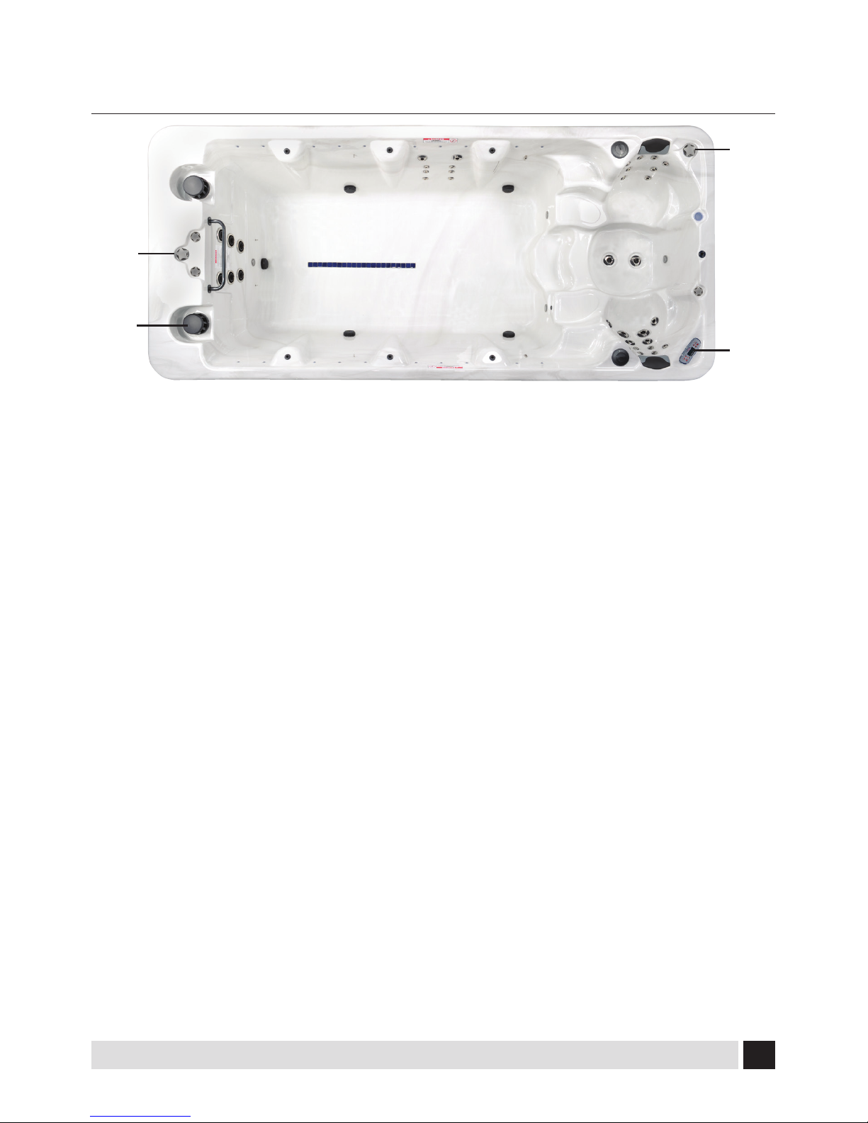
Swim Spa System Components.....................10
Swim Spa Components...................................11
Jets and Air Controls........................................12
Jets............................................................................12
Cleaning or Replacing Jets...............................12
Electrical Information......................................13
Important Safety Instructions.........................13
Installation Options.............................................13
Amperage Charts.................................................15
Start Up Procedures.........................................16
Priming Your Swim Spa.....................................16
TP600 Control Panel.........................................17
Main Menus...........................................................17
Filling Your Spa.....................................................18
Spa Behavior..........................................................18
Temperature and Temp Range........................19
Mode - Rest and Ready......................................20
Show and Set Time-of-Day...............................20
Flip (Invert Display)..............................................20
Restricting Operation.........................................21
Unlocking................................................................21
AdjustingFiltration..............................................21
Wi-Fi Connectivity................................................21
GFCI Trip Test.........................................................21
TP800 Control Panel.........................................22
Button Functions..................................................22
The Main Screen...................................................23
Spa & Shortcut Screens......................................23
The Settings Screen.............................................24
Filling Your Spa.....................................................25
Spa Behavior..........................................................26
Time-of-Day............................................................26
AdjustingFiltration..............................................27
Restricting Operation.........................................27
Unlocking................................................................27
Wi-Fi Connectivity................................................27
GFCI Test Feature..................................................27
Scenes......................................................................27
Bluetooth Connection.....................................28
WiFi Connectivity..............................................29
Smart Device WiFi Spa Controls.....................29
Getting Started.....................................................29
After Application Download............................29
Connect to your Spa...........................................29
Connecting to WiFi Network...........................30
Application Functions........................................31
Settings....................................................................31
Setting Time..........................................................31
Setting Filter Cycles.............................................32
Controls...................................................................32
SafetyFeatures..................................................33
Automatic Time Outs.........................................33
Common LCD Equipment Messages............33
Common LCD Messages....................................34
TABLE OF CONTENTS

44
Swim Spa
Maintenance......................................................35
Water Chemistry...................................................35
Sanitizing.................................................................35
pH Level...................................................................35
Water Maintenance.............................................35
Sanitizing With Ozone........................................36
Specialty Chemicals............................................36
Draining Your Swim Spa....................................36
Filter Maintenance...............................................37
Winterizing.............................................................37
Swim Spa Cabinet Care.....................................38
Swim Spa Surface Care and Cleaning..........38
Underwater LED light cluster..........................38
Common Water Problems...............................40
Common Hardware Problems........................43
Swim Spa Soaking Guidelines........................45
MXBP20 Series System Wiring Diagram......47
VS501 Series System Wiring Diagram..........48
MXBP501 Series System Wiring Diagram....49
GS501 Series System Wiring Diagram..........50
MXBP21 Series System Wiring Diagram......51
Safety Sign/Limited Warranty Summary.....52
Copyrights and Trademarks...........................53
Notes...................................................................54
TABLE OF CONTENTS

55
Swim Spa
IMPORTANT SAFETY INSTRUCTIONS
1. WARNING - To reduce the risk of injury,
do not permit children to use this prod-
uct unless they are closely supervised at
all times.
2. A wire connector is provided on this unit
to connect a minimum 6 AWG (5.15 mm2)
solid copper conductor between this unit
and any metal equipment, metal enclosu-
res of electrical equipment, metal water
pipe, or conduit within 5 feet (1.5m) of
the unit.
3. (For cord-connected/convertible units)
DANGER - Risk of injury.
a. Replace damaged cord immedi-
ately.
b. Do not bury cord.
c. Connect to a grounded, ground-
ing type receptacle only.
4. DANGER - Risk of Accidental Drown-
ing. Extreme caution must be exercised
to prevent unauthorized access by
children. To avoid accidents, ensure that
children cannot use this spa unless they
are supervised at all times.
5. DANGER - Risk of injury. The suction
ttings in this spa are sized to match the
specic water ow created by the pump.
Should the need arise to replace the
suction ttings or the pump, be sure that
the ow rates are compatible.
Never operate spa if the suction ttings
are broken or missing. Never replace a
suction tting with one rated less than
the ow rate marked on the original suc-
tion tting.
6. DANGER - Risk of Electric Shock. Install at
least 5 feet (1.5m) from all metal surfaces.
As an alternative, a spa may be installed
within 5 feet of metal surfaces if each
metal surface is permanently connected
by a minimum 6 AWG (5.15 mm2) solid
copper conductor to the wire connector
on the terminal box that is provided for
this purpose.
7. DANGER - Risk of Electric Shock. Do not
permit any electric appliance, such as a
light, telephone, radio, or television,
within 5 feet (1.5m) of a spa.
8. WARNING - To reduce the risk of injury:
a. The water in a spa should never
exceed 40°C (104°F).Water tem-
peratures between 38°C (100°F)
and 104°F (40°C) are considered safe for a
healthy adult. Lower water temperatures
are recommended for young children and
when spa use exceeds 10 minutes.
b. Since excessive water temperatures
have a high potential for causing fetal
damage during the early months of preg-
nancy, pregnant or possibly pregnant
women should limit spa water tempera-
tures to 38°C (100°F).
c. Before entering a spa the user should
measure the water temperature since the
tolerance of water temperature-regulat-
ing devices varies.
READ AND FOLLOW ALL INSTRUCTIONS

66
Swim Spa
d. The use of alcohol, drugs, or medica-
tion before or during spa use may lead
to unconsciousness with the possibility of
drowning.
e. Obese persons and persons with a
history of heart disease, low or high
blood pressure, circulatory system prob-
lems, or diabetes should consult a physi-
cian before using a spa.
NOTE: Check with your state/local code
enforcement ocer to determine electrical
code requirements and compliance. Use a
qualied licensed electrician to complete all
spa nal electric connections.
TO AVOID RISK OF ELECTRICAL SHOCK:
1. A green colored terminal or a terminal
marked G, GR, Ground, Grounding, or the
international symbol is located on
the side of the supply terminal box or
compartment. This terminal must be
connected to the grounding means
provided in the electric supply service
panel, using a continuous copper wire
equivalent in size to the circuit conduc-
tors supplying this equipment.
*IEC Publication 417, Symbol 5019.
2. At least two lugs marked “BONDING
LUGS” are provided on the external sur-
face or on the inside of the supply termi-
nal box or compartment. Connect the
local common bonding grid (house-hold
ground) in the area of the hot tub or spa
to these terminals, using an insulated or
bare copper conductor not smaller than
No. 6 AWG.
3. All eld-installed metal components such
as rails, ladders, drains or similar hard
ware located within 5 ft. of the spa or
hot tub shall be bonded to the equip-
ment grounding bus with copper con-
ductors not smaller than No. 6 AWG.
4. Never connect unit to a power supply
with a load controller.
5. Install to provide drainage of compart-
ment for electrical components.
6. The electrical supply for this product
must include a suitably rated switch
or circuit breaker to open all ungrounded
supply conductors. This disconnecting
means must be readily accessible for
operation but installed at least 1.5m
from the spa. All electrical connections
should comply with local regulations.
SAVE ALL INSTRUCTIONS
Caution: Risk of electrical shock.
Read and follow all instructions.

77
Swim Spa
Dos and Don’ts of Spa Care:
Do:
• Save these instructions!
• Replace the cover immediately after use.
•
Keep the cover locked when spa is not
in use.
• Be aware of the dangers of a wet and
slippery surface. Use caution when
entering and exiting your spa.
• Have a licensed electrician make all nal
electrical connections.
• Replace worn, frayed or broken electrical
cords.
• Keep the water chemistry correctly
balanced. Untreated spa water will cause
problems with your spa and equipment
as well as being a health risk.
• Clean the spa lter monthly or as needed.
• Position the spa so that all sides remain
accessible for maintenance.
• Use a bathing cap for long hair.
• Refer to information on hyperthermia,
next column.
• Use only authorized spa care products
for the best performance and to keep
the water properly balanced.
Don’t:
• Use the spa at 104°F (40°C) for long
periods of time (more than 30 minutes).
See Hyperthermia, next column.
• Use an extension cord to power your spa.
• Allow anyone to stand on the spa cover.
It is not designed to support weight.
• Power the spa unless it is lled with water
5-6” below top of the lip of the spa.
• Operate the pump on high speed for ex-
tended periods of time with the cover in
place. Extended operation can cause heat
build-up and interfere with spa operation.
Hyperthermia
The causes, symptoms, and eects of
hyperthermia may be described as follows:
Hyperthermia occurs when the internal
temperature of the body reaches a level
several degrees above the normal body
temperature of 98.6°F (37°C). The symptoms
of hyperthermia include an increase in the
internal temperature of the body, dizziness,
lethargy, drowsiness, and fainting. The eects
of hyperthermia include:
a. Failure to perceive heat
b. Failure to recognize the need to exit spa
or hot tub
c. Unawareness of impending hazard
d. Fetal damage in pregnant women
e. Physical inability to exit the spa or hot
tub, and
f. Unconsciousness resulting in the danger
of drowning.
WARNING The use of alcohol, drugs,
or medication can greatly increase the
risk of fatal hyperthermia.

88
Swim Spa
SWIM SPA INSTALLATION
Danger: Electrical shock risk. Install at
least 1.5m from all metal surfaces.
The electrical supply for this product must
include a suitably rated switch or circuit
breaker to open all ungrounded supply
conductors. The disconnecting means must
be readily accessible but installed at least 1.5
meters from the Swim spa water. All electrical
connections should comply with local
regulations.
The appliance should be supplied through
a residual current device
(RCD) or Ground Fault
Interrupter (GFCI) with a
rated tripping current not
exceeding 30 mA. Means
for disconnection must
be incorporated in the
xed wiring in accordance
with the wiring rules. Parts containing live
parts, except parts supplied with safety
extra-low voltage not exceeding 12 V, must be
inaccessible to a person in the bath. Earthed
appliances must be permanently connected
to xed wiring.
Site and Positioning
MAAX® Spas recommends that a Swim spa be
placed in its nal installation site by crane. In
any installation where a crane cannot be used,
you may want to consult with a professional
rigging company.
When utilizing a crane for delivery, be sure
that crane operator understands the weight
of the Swim spa, the height it must be lifted,
and the distance that the crane boom must
travel. Be sure that the crane operator uses
an 8’ spreader bar and that the straps wrap all
the way around the bottom frame of the Swim
spa.
Locate the Swim spa on a solid, level
foundation keeping in mind the weight of
the lled Swim spa (in excess of 18,000 lb.
(8165 kg.) on some models). If you have any
doubts about the load bearing ability of your
chosen site, contact an architect or a building
contractor. The entire perimeter of the Swim
spa Frame and bottom must be evenly
supported.
We recommend that you provide a concrete
foundation pad for the Swim spa. The
foundation pad should be wider and longer
than the Swim spa by at least 12 inches (30
cm) in each direction. Failure to provide a
level surface could structurally damage your
Swim spa and void the warranty.
The Swim spa must be installed to allow
access for service and maintenance on all
four sides; therefore, if you choose to install
your Swim spa below grade level, you will be
required to have a vault or pit constructed
to prevent ground water, rain, snowmelt, or
sources of water from collecting around the
equipment of the Swim spa. The vault must
have either sucient drainage through a drain
line or through the use of a sump pump. The
vault must have adequate safe access as to
allow for routine maintenance of the Swim spa
components.
IMPORTANT: Proper drainage must be
provided to keep base dry, especially if
installed below grade/in a pit.

99
Swim Spa
WARNING: ACCESS TO THE Swim spa
SHOULD BE CONTROLLED IN ACCORDANCE
WITH ALL APPLICABLE NATIONAL AND
LOCAL CODES. IN SOME LOCATIONS THIS
MAY INCLUDE AN APPROVED FENCE WITH
SELF-CLOSING, SELF-LOCKING GATE
AND/OR A LOCKABLE SAFETY HARDCOVER
FOR OUTDOOR USE AND A LOCKABLE
DOOR AND/OR SAFETY HARDCOVER FOR
INDOOR USE.
Outdoor Installation
The following considerations apply when
installing your Swim spa outdoors:
1. Local codes pertaining to fencing.
2. Local electrical and plumbing codes.
3. View from your house.
4. Wind direction.
5. Exposure to sunlight.
6. Location relationship to trees (twigs,
leaves and shade).
7. Dressing and bathroom location.
8. Storage area for maintenance equipment
and chemicals.
9. Location to facilitate adult supervision.
10. Landscaping and night time lighting.
11. Accessibility to equipment.
12. Location and routing of power supply to
Swim spa and foot trac.
Indoor Installation
In addition to the Outdoor installation
consideration, please also understand that the
following considerations apply when installing
your Swim spa indoors:
1. Indoor Swim spas promote high
humidity. Using either ventilation fans or
commercial grade de-humidiers will help
to reduce the humidity. Consult your
dealer for details.
2. Floor drains must be provided near the
Swim spa to drain o water that
may cause falls and /or water damage.
Water will splash out of the Swim spa
during normal use when swimming and
when exiting the Swim spa.
3. Surface area of foundation pad and
surrounding area should be at with a
non-skid nish. Carpeting or other
porous materials may retain moisture,
which leads to mold, mildew and odors
and is not recommended.
4. Walls, ceilings, woodwork should be made
of materials capable of withstanding high
humidity.
5. MAAX® Spas only recommends the use of a
concrete foundation pad to support your
Swim spa. If you intend to install your
Swim spa in an area where you cannot
utilize a concrete foundation pad, you
must consult with a structural engineer
to ensure the oor load bearing capacities
are adequate to support the concentrated
Swim spa weight, the weight of the
Swim spa occupants, and any furniture
or people that will be using the immediate
area of the Swim spa.
6. During shipment from the factory,
plumbing components may loosen;
therefore it is imperative that the
Swim spa is double checked for leaks
before installing to avoid possible water
damage. Your dealer may include this
service in their installation procedures.
7. Indoor sunrooms are capable of
maintaining high ambient temperatures
which may aect the Swim spa water
temperature. It is NOT recommended that
you operate your lter cycles for longer
than 4 hours per day under these
conditions.
Danger: Electrical shock risk. Install at least
5 feet (1.5 m) from all metal surfaces.

10 10
Swim Spa
SWIM SPA SYSTEM COMPONENTS
A. Filter Skimmer/Weir: Removes
oating debris from the water surface,
provides a water return path to equipment,
and houses water lter elements.
B. Topside Control Panel: Used to control
temperature setting, jet pumps, circulation
system, underwater lights and ambient
eect lighting.
C. Air Controls: Increases or decreases air
entering the jets. Close during heating
for maximum eciency. It is recom-
mended that air controls to the swim jets
remain closed during swimming to provide
a clearer stream of water which is free from
air bubbles.
D. Equipment Pack Service Panel (no user
serviceable parts): Spa support system
consisting of several of the following
devices: electronic control pack,
pumps, heater, UV water sanitizer, ozone
generator, LED lighting interface
and associated electrical controls (not
shown).
E. Drain Access (Adjacent to the equipment
service panel): Drain faucets
are located immediately behind the front
door panel. Remove panel to access (not
shown).
F. Manufacturer’s Identication Label:
Contains identication information for
warranty service (serial number, model
number, etc.) and electrical information
(ampere rating and ampere requirements).
Located on the lower right side of the front
door panel (not shown).
G. Diverter Valve: Used to direct the ow
of water between the massage jets in
the hydrotherapy seats and the swim
jets. By turning the diverter valve
clockwise, the water is directed to the
massage jets in the hydrotherapy seats and
by turning the diverter jet counterclockwise,
the water is directed to the swim jets.
A
B
C
G

11 11
Swim Spa
SWIM SPA COMPONENTS
Reference only. Equipment is not always as shown
Note: No consumer serviceable parts. We
recommend that only an authorized service
technician perform swim spa repair or service.
A. Pumps: Each pump features single or
dual-speed capacity. Low speed is utilized
for water circulation during ltration and
heating, and for lighter therapy and exercise
programs; high speed is engaged for
maximum action of the jets when deeper
therapy or more rigorous exercise programs
are desired. All pump functions are activated
by topside controls.
B. Electronic Control Pack: All swim spa
functions are operated by this control. There
are no user-serviceable components in this
control. Opening this control may subject
you to high voltage and danger of electrical
shock or electrocution.
Warning and Installation Label: Contains
important safety information, hazard
warnings and installation instructions.
C. Slice Valve: Used to shut o water ow
from the swim spa vessel to pumps
and electronic control pack while servicing.
Quantity will vary depending on model.
All valves should be open during normal
operations.
D. ElectricalConnections: Contains receptacles
for electrical connections. Connections
are made during manufacture of the pool
and by your electrician.
E. Heater Assembly: Thermostatically
controlled and equipped with an overheat
safety shut-o.

12 12
Swim Spa
JETS AND AIR CONTROLS
Swim Area Jets
Swim sp jets are designed to produce a smooth
ow of water with high output to create a
consistent swim stream. Whether you want to
swim or walk/jog against the force of the jets,
you will nd the ow of water deep enough
and swift enough to meet your individual
needs.
Hydrotherapy Area Jets
All spa jets are individually engineered
to provide a unique hydro-massage.
Depending on the model, your spa will have a
combination of the following jets.
Directional Jets
Positioned to focus on large muscle groups,
these jets deliver a concentrated, high volume
stream of water for a deep massage. Each jet
is fully adjustable, allowing users to set the
water ow to the most comfortable setting.
Nozzle can be rotated to target sore muscles.
Rotating Jets
Positioned to focus on muscle tension zones,
these jets deliver a spinning V-shaped water
stream for a gentle, pulsating massage. Each
jet is fully adjustable, allowing for comfortable
water ow settings for everyone to enjoy.
Euro Jets
Positioned in the foot well or shoulder areas,
these jets deliver a penetrating massage to
dissolve tension. This jet may be the entry
point for ozone produced during automatic
ltration and therefore it is not adjustable.
Note: Ozone production is stopped when
functions are activated on control panel.
Cleaning or Replacing Jets
Hard water can cause calcium/mineral
buildup that can restrict or bind the jets. A jet
consists of a face plate and a nozzle. Rotate
these parts weekly and remove/clean monthly
to ensure free movement.
NOTE: It is not necessary to drain the spa to
clean or remove the jets.
Rotating Jets
• Rotate the jet face left and right
• Return face plate to full open position
• Turn the jets on high speed
• Twist the nozzle left and right
• Rotate the nozzle in the socket
NOTE: If the jet insert disengages from the
spa housing, see steps to reinstall below.
Cleaning Jets
• To REMOVE the jet insert, use the palm of
your hand to exert pressure on the face of the
jet. Turn counterclockwise until the jet ‘clicks’.
Gently pull the jet assembly from the housing.
• To CLEAN the jet insert and housing, use a
pressurized hose and spray the inside of the
jet. Soak the jet in a diluted spa cleaning
solution, rinse. Wipe the inside of the housing
to remove any debris.
• To REINSTALL the jet, line up the tab on
the backside of the barrel with the groove in
the body. Use the palm of your hand to gently
tap the jet until it snaps into position.

13 13
Swim Spa
ELECTRICAL INFORMATION
Important Safety Instructions
All electrical connections to this spa package
MUST be accomplished by a qualied
licensed electrician in accordance with the
National Electrical Code (NEC) and with state/
local electrical codes in eect at the time
of installation.
NOTE: Prior to performing any service to
the spa equipment, turn OFF all primary
electrical power at the main circuit breaker
or disconnect panel.
To make spa electrical connections, remove
the exterior equipment access panel, locate
the electrical control box, remove the control
box cover and follow the wiring diagram on
the inside of the control box cover.
Connections should be made using copper
conductors only. Connecting wires, circuit
breakers, or fuses must all be sized to accom-
modate the Total Ampere load as specied
on the equipment label.
This equipment is designed to operate on
60Hz alternating current only, at 240 volts.
NOTE: All unions must be hand-tight and
all slice valves must be locked in the OPEN
position before lling or relling spa!
A clip is provided to help keep the slice
valve open. Run spa and check for union
leaks before reinstalling front panel.
Ground-Fault Circuit Interrupter
A qualied licensed electrician shall connect
the spa to a circuit protected by a GFCI or
RCD (European). This is a requirement by
the National Electric Code, article 680-42,
and is also in compliance with Underwriter’s
Laboratories, Inc.
Installation Options
A hole may need to be drilled in the pedestal
or base for the swim spa electrical service
entrance.
Refer to the manufactures’s nameplate
located on the kick plate to determine your
spa’s ampere requirements.
Spas installed for 240 volt, 60 Hz, single
phase operation require a 4-wire, 50 or 60
amp 240 volt sub-feed in non-metallic pipe
to the spa equipment compartment (line 1,
line 2, neutral and ground). A green colored
terminal (or wire connector marked “G”,
or “GR”, or “Grounding”) is provided in the
control box. To reduce the risk of electrical
shock, connect this terminal or connector
to the grounding terminal of your electrical
service or supply panel with a continuous
green insulated copper wire equivalent to
the circuit conductor supplying this equip-
ment, but no smaller than No. 12 AWG. A
second pressure wire connector is provided
on the surface of the control box for bond-
ing to local ground points. To reduce the
risk of electrical shock, this connector should
be bonded with a No. 6 AWG copper wire to
any metal ladders, water pipes, or any metal
within 5 feet of the spa.
Note: Copper wire is strongly recommend-
ed for all electrical connections.
Caution: Risk of electrical shock.
Read and follow all instructions.

14 14
Swim Spa
240 Volt Installation Units
Electrical Requirements
Letter Requirement
A- 240 volt/60 amp.
- 60 Hz
- Single phase
- 4-wire service (line 1, line 2 neutral
and ground)
B- 240 volt/50 amp.
- 60 Hz
- Single phase
- 4-wire service (line 1, line 2, neutral
and ground)
C- 240 volt/40 amp.
- 60 Hz
- Single phase
- 4-wire service (line 1, line 2, neutral
and ground)
DNOT NORTH AMERICAN
- 240 volt
- 50 Hz
- Single-, two-, or three- phase
service
- Refer to wiring diagram or pouch
on control system inside cabinet for
specic wiring and phase info.
240 Volt Installation Units
Electrical Requirements
Number Meaning
1The heater will remain running
with the high speed pump(s).
2
The heater can be activated
only with the pump on low
speed. Only the spa light can
be operating at the same time
without disabling the heater.
See your authorized dealer to
select this option.
INSTRUCTIONS:
Find your swim spa listed in the chart on the next page then refer to the key below
to determine what electrical service your swim spa requires.

15 15
Swim Spa
DEDICATED 240V SWIM SPAS
MODELS NORTH AMERICA NOT NORTH AMERICA
240V/60A 240V/50A 240V/40A 240V/50Hz
DT6 (Swim side) A1 C2 D
DT6 (Spa side) B1 C2 D
LT6 A1 C2 D
MT6 A1 C2 D
RB4 A1 C2 D
RL4 A1 C2 D
RS1 A1 C2 D
RS2 A1 C2 D
XB4 A1 C2 D
XL4 A1 C2 D
XS1 A1 C2 D
XSD (Swim side) A1 C2 D
XSD (Spa side) B1 C2 D
XSL A1 C2 D
XSP A1 C2 D

16 16
Swim Spa
START UP PROCEDURES
Follow recommendations for site location and
electrical connection.
1. Use standard“tap water” to ll the
swim spa by draping a garden hose
over the wall. Take care to wrap the metal
end of the hose with a soft cloth or set the
end of the hose in the lter canister to
protect the swim spa surface from
the metal end of the hose. The metal end
of your hose can become rough or jagged
and may scratch the surface of your
swim spa, and this damage is not
covered under your warranty. Fill the
swim spa until the water level is 2 to
2.5 cm from the top lip.
Never use “softened” water in your pool
or spa. Softened water can impact the
chemical balance of the water and lead to
degradation of metal plumbing ttings.
2. After you have assured that the
swim spa is full of water and that all
plumbing valves are open, turn power on
at circuit breaker or disconnect panel.
3. Open the air controls, located on the top
lip, and cycle the jets from high to low.
Water should come from the therapy jets. If
water ow is not established, turn o jets
and see Priming Your Swim Spa.
4. Add chemicals. See Chemical Treatment
and Water Maintenance section. Follow
Operating Instructions for your particular
model to set heat to the desired
temperature. Initially, you may nd that the
swim spa requires 18 to 24 hours on
230 Volt installations to reach temperature.
Keep your thermal cover on the unit and
close the air controls to help the heating
process.
Priming Your Swim Spa
When lling your swim spa for the rst
time or, after draining and relling the swim
spa, you may need to bleed air from the
system. Should you experience an air-lock on
Pump 1, remove the lter basket cover, insert
a garden hose through the center
hole of the lter as far as possible without
using force. Hold the hose in place and
turn on the water. This forces water into the
pump and forces the air out.
Important: Do not operate the Swim Spa
without full water ow.

17 17
Swim Spa
TP600 CONTROL PANEL
NOTE: The look of your topside control panel design and buttons will vary according to brand
and features available on your swim spa. See table below for pictures and explanation of
TP600 Control Panel button functions.
MAIN MENUS
NAVIGATION
Navigating the entire menu structure is
done with 3 buttons on the control panel:
Temperature Up, Temperature Down and Light
buttons.
Panels have separate WARM (Up) and COOL
(down) buttons which are used to increase or
decrease the temperature. These buttons are
also used to navigate through menus.
The LIGHT button is used to activate spa lights
and is also used to choose various menus to
navigate each section.
Typical use of the Temperature buttons allows
changing the Set Temperature while the
numbers are ashing in the LCD screen.
Numbers will begin ashing when either one
of the temperature buttons are pressed.
Pressing the LIGHT button while the numbers
are ashing will take you to the menus.
The menus can be exited with certain button
presses. Simply waiting for several seconds
will return the panel operation to normal.
BUTTON NAME FUNCTION
Jets 1
Jets 2
Temperature
Up
Temperature
Down
Light
Activates jets on
low or high setting
Increases
temperature
and allows for
navigation
through system
Decreases
temperature
and allows for
navigation
through system
Activates lights
and chooses
menus to navigate
through system

18 18
Swim Spa
FILLING YOUR SPA
PREPARATION AND FILLING
Fill the spa to its correct operating level (5-6
inches below top of spa lip). Open all valves
and jets in the plumbing system before lling
to allow as much air as possible to escape
from the plumbing and the control system
during the lling process.
PRIMING MODE
This mode will last 4-5 minutes or you can
manually exit the priming mode after the
pump(s) have primed. Regardless of whether
the priming mode ends automatically or
you manually exit the priming mode, the
system will automatically return to normal
heating and ltering at the end of the priming
mode. During the priming mode, the heater
is disabled to allow the priming process
to be completed without the possibility of
energizing the heater under low-ow/no-ow
conditions. Nothing comes on automatically,
but the pump(s) can be energized by pushing
the “Jet” buttons. If the spa has a Circ Pump,
it can be activated by pressing the“Light”
button during Priming Mode.
PRIMING THE PUMPS
After the display has gone through screens:
“RUN” “PMPS” “PURG” “AIR” “-- -- -- --” ,
push “Jet” button once to start Pump 1 in low-
speed and again to switch to high-speed. Push
the Pump 2 button (if you have a 2nd pump)
to turn it on. The pumps will not be running in
high-speed to facilitate priming. If the pumps
have not primed after 2 minutes, and water is
not owing from the jets in the spa, turn o
the pumps and repeat.
NOTE: Turning the power o/on again
will initiate a new pump priming session.
Sometimes turning the pump o/on helps
it to prime. If the pumps will not prime after
5 times, turn power o and call for service.
IMPORTANT: A pump should not be allowed to
run without priming for more than 2 minutes.
Under NO circumstances should a pump be
allowed to run without priming beyond the
end of the 4-5 minute priming mode. Doing
so may cause damage to the pump and cause
the system to energize the heater and go into
an overheat condition.
EXITING PRIMING MODE
Manually exit Priming Mode by pressing either
Temperature button. If you do not manually
exit the priming mode, it will be automatically
terminated after 4-5 minutes. Be sure that the
pump(s) have been primed by this time.
Once the system has exited Priming Mode,
the top-side panel will momentarily display
the set temperature but the display will not
show the temperature yet because the system
requires approximately 1 minute of water
owing through the heater to determine the
water temperature and display it accurately.
SPA BEHAVIOR
Pumps
Press the “Jets 1” button once to turn pump 1
on or o, and to shift between low- and high-
speeds if equipped. If left running, the pump
will turn o after a time-out period. The pump
1 low-speed will time out after 30 minutes. The
high-speed will time out after 15 minutes.
On non-circ systems, the low-speed of pump
1 runs when the blower or any other pump is
on. If the spa is in Ready Mode, Pump 1 low
may also activate for at least 1 minute every
30 minutes to detect the spa temperature and
then to heat to the set temperature if needed.
When the low-speed turns on automatically,
it cannot be deactivated from the panel,
however the high speed may be started.

19 19
Swim Spa
Circulation Pump Modes
The circ pump (if your spa is equipped with
one) operates continuously (24 hours) with
the exception of turning o for 30 minutes at a
time when the water temperature reaches 3°F
(1.5°C) above the set temperature (most likely
to happen in very hot climates).
Filtration and Ozone
On non-circ systems, Pump 1 low and the
ozone generator will run during ltration. On
circ systems, the ozone will run with
the circ pump.
The system is factory-programmed with
one lter cycle that will run in the evening
(assuming the time-of-day is properly
set) when energy rates are often lower. The
lter time and duration are programmable. A
second lter cycle can be enabled as needed.
At the start of each lter cycle, the blower (if
there is one) or Pump 2 (if there is one) will run
briey to purge its plumbing to maintain good
water quality.
Freeze Protection
If the temperature sensors within the heater
detect a low enough temperature, the
pump(s) and the blower automatically
activate to provide freeze protection.
The pump(s) and blower will run either
continuously or periodically depending
on conditions.
In colder climates, an optional additional
freeze sensor may be added to protect against
freeze conditions that may not be sensed by
the standard sensors. Auxiliary freeze sensor
protection acts similarly except with the
temperature thresholds determined by the
switch. See your dealer for details.
Clean-up Cycle (optional)
When a pump or blower is turned on by a
button press, a clean-up cycle begins 30
minutes after the pump or blower is
turned o or times out. The pump and the
ozone generator will run for 30 minutes or
more, depending on the system. On
some systems, you can change this setting.
TEMPERATURE & TEMP RANGE
Adjusting the Set Temperature
Pressing Up or Down temperature buttons
will cause the temperature to ash. Pressing a
temperature button again will adjust the set
temperature in the direction indicated on the
button. When the LCD stops ashing, the spa
will heat to the new set temperature.
Press-and-Hold
If a Temperature button is pressed and
held when the temperature is ashing, the
temperature will continue to change
until the button is released.
Dual Temperature Ranges
This system incorporates two temperature
range settings with independent set
temperatures. The High Range designated in
the display by an“up” arrow, and the Low
Range designated in the display by a“down”
arrow. These ranges can be used for various
reasons, with a common use being a “ready to
use” setting vs. a “vacation” setting.
The Ranges are chosen using the menu
structure below. Each range maintains its own
set temperature as programmed by
the user. This way, when a range is chosen, the
spa will heat to the set temperature associated
with that range.
For example:
High Range may be set between 80°F - 104°F.
Low Range may be set between 50°F - 99°F.
Freeze Protection is active in either range.

20 20
Swim Spa
MODE - REST AND READY
In order for the spa to heat, a pump needs to
circulate water through the heater. The pump
that performs this function is known as the
“heater pump.”The heater pump can be either
a 2-Speed Pump 1 or a circulation pump.
If the heater pump is a 2-Speed Pump 1,
READY Mode will circulate water every 1/2
hour, using Pump 1 Low, in order to
maintain a constant water temperature,
heat as needed, and refresh the temperature
display. This is known as “polling.”
REST Mode will only allow heating during
programmed lter cycles. Since polling does
not occur, the temperature display
may not show a current temperature until the
heater pump has been running for a minute
or two.
Circulation Mode
If the spa is congured for 24HR circulation,
the heater pump generally runs continuously.
Since the heater pump is always running, the
spa will maintain set temperature and heat as
needed in Ready Mode, without polling.
In Rest Mode, the spa will only heat to set
temperature during programmed lter times,
even though the water is being ltered
constantly when in Circulation Mode.
Ready-in-Rest Mode
READY/REST appears in the display if the
spa is in Rest Mode and Jet 1 is pressed. It is
assumed the spa is being used and will heat
to set temperature. While Pump 1 High can
be turned on and o, Pump 1 Low will run
until set temperature is reached, or 1 hour has
passed. After 1 hour, the System will revert
to Rest Mode. This mode can also be reset by
entering the Mode Menu and changing it.
SHOW & SET TIME-OF-DAY
Setting the time-of-day can be important
for determining ltration times and other
background features. From the main menu,
activate the temperature ashing. While
the temperature is ashing, press “Light”
repeatedly until “TIME” is displayed on the
screen. Proceed to set current time using the
up and down temperature buttons. When
in the TIME menu, SET TIME will ash on the
display if no time-of-day is set in the memory.
24-hour time display can be set under the
PREF menu.
Note: If power is interrupted to the system,
Time-of-Day is not stored. The system will
still operate and all other user settings will
be stored. If lter cycles are required to run
at a particular time of day, resetting the
clock will return the lter times to the actual
programmed periods. When the system starts
up, it defaults to 12:00 Noon, so another way
to get lter times back to normal is to start up
the spa at noon on any given day. SET TIME
will still ash in the TIME Menu until the time is
actually set, but since the spa started at noon,
the lter cycles will run as programmed.
FLIP (INVERT DISPLAY)
From the main screen, activate the
temperature ashing. While the temperature
is ashing, press “Light” repeatedly until
“FLIP” is displayed on the screen. While “FLIP”
is displayed, press either the up or down
temperature button to invert the screen.
Follow the same procedures to ip it back.
This manual suits for next models
1
Table of contents
Other MAAX Spas Hot Tub manuals
Popular Hot Tub manuals by other brands

Master Spas
Master Spas Honolulu Owner's manual & limited warranty

Aquatic
Aquatic MILLENNIUM 10 AI10MIL8248 Specifications

Intex
Intex Greywood Deluxe owner's manual

Aquatic
Aquatic iNfiNity serIes Owner's manual & installation guide

Master Spas
Master Spas INT H2X CHALLENGER 19D owner's manual

Daga
Daga HM-2200 instruction manual