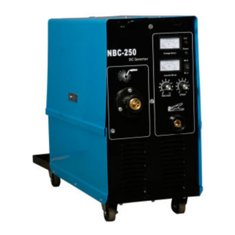
Mac Afric EWELDM253 User manual

THANKS FOR PURCHASING OUR PRODUCT
EWELDM253
Inverter MIG/MMA Semi-auto ARC Welding Machine
Operation Manual
(Read the manual carefully before installation ,operation and maintenance)
Advanced Product

SAFETY PRECAUTIONS
Follow these precautions carefully. Improper use of any welder
can result in injury or death.
1. ONLY CONNECT WELDER TO A POWER SOURCE FOR WHICH IT WAS DESIGEND.
The specification plate on the welder lists this information. When welding outdoors only use an
extension cord intended for such use.
2. ONLY OPERATE WELDER IN DRY LOCATIONS and on cement or masonry floor. Keep
area clean and uncluttered.
3. KEEP ALL COMBUSTIBLES AWAY FROM WORK SITE.
4. DO NOT WEAR CLOTHING THAT HAS BEEN CONTAMINATED with grease or oil.
5. KEEP CABLES DRY AND FREE FROM OIL AND GREASE and never coil around
shoulders.
6. SECURE WORK WITH CLAMPS or other means; don't over reach when working.
7. NEVER STRIKE AN ARC ON A COMPRESSED GAS CYLINDER
8. DON'T ALLOW THE INSULATED PORTION OF THE ELECTRODE HOLDER TO TOUCH
THE WELDING GROUND WHILE CURRENT IS FLOWING.
9. SHUT OFF POWER AND UNPLUG MACHINE WHEN REPAIRING OR ADJUSTING.
Inspect before every use. Only use identical replacement part.
10. FOLLOW ALL MANUFACTURER'S RULES on operating switches and making
adjustments.
11. ALWAYS WEAR PROTECTIVE CLOTHING when welding . This includes: long sleeved
shirt(leather sleeves), protective apron without pockets, long protective pants and boots. When
handing hot materials, wear asbestos gloves.
12. ALWAYS WEAR A WELDER'S HELMET WITH PROTECTIVE EYE PIECE when welding.
Arcs may cause blindness. Wear a protective cap underneath the helmet.
13. WHEN WELDING OVERHEAD, BEWARE OF HOT METAL DROPPINGS. Always protect
the head, hand, feet and body.
14. KEEP A FIRE EXTINGUISHER CLOSE BY AT ALL TIMES.
15. DO NOT EXCEED THE DUTY CYCLE OF THE MACHINE. The rated cycle of a welding
machine is the percentage of a ten minute period that the machine can operate safely at a
given output setting.
16. KEEP ALL CHILDREN AWAY FROM WORK AREA. When storing equipment, make sure
it is out of reach of children.
17. GUARD AGAINST ELECTRIC SHOCK. DO not work when tired. Do not let body come
In'contact with grounded surfaces.

Prolegomenon
We do very appreciated for your selecting our products.
This kind of welding power Model EWELDM253 is taken foreign advanced technology to develop
and manufacture the new generation inverter integrated controlling Semi-auto MIG/MAG ARC and
MMA Welding machine.
It can be composed the EWELDM253 MIG/MMA multi function Welding system equipped with
wire feeder and welding gun .It has many characteristic such as easy Arc starting .good Arc springiness
.adjustable arc thrusting ,low splash,good welding form ,easy welding operation,wide range and
electricity save.
The MIG/MMA multi function welding machine model EWELDM253 is advanced welding
machine and it can be compared with foreign products.
This operation manual can help you for the machine installation, operation and maintenance
correctly and safely.Pay attention to the points as following.
.Installation of the power cord. Be grounded correctly.
. Don't put sundries under the welder.Otherwise it will affect the heat released.
. Installation for the positive and negative cable of the power output.
. Welding voltage selection
. Welding current selection (speed of wire feeder)
. Selection of Arc thrusting(arc force)
The amendment right and the explanation right of the manual belonging to my company.We have
no special notice if the manual is amended.
1

1. Main characteristic and suitable range
This kind of welding power Model EWELDM253 is taken foreign advanced technology to
develop and manufacture the new generation inverter integrated controlling Semi-auto MIG/MAG Arc
welding machine.It makes use of the import key parts such as Siemens IGBT module of Germany,alloy
magnetic core and the resume diode module of America. It has the perfect performance of high quality ,
good reliability, quick speed of welding current, steady welding process,low splash and good welding
form . Anyway,It becomes the welding very easy.
1.1 Structure of the EWELDM253 multi function welding machine
a.The name of the model
EWELDM253
Model improvement
max welding current
MIG/MMA multi Arc welding machine
b. Composing of the product
This product is composed by three parts as following
★
Power source(EWELDM253)
★
welding gun
1.2 Suitable range of the EWELDM253
★
Suitable material: low-carbon steel, stainless steel
★
Thickness of the material:low-carbon steel and stainless:more than 0.5mm
★
Suitable position:all positions
★φ
Suitable wire : 0.8,1.0,1.2,1.6solid wire/flux cord wire.
1.3 Characteristic of EWELDM253
★
Wide output current 10-250A: 0.8----------- 30-150A
1.0------------40-250A
1.2------------80-250A
★
Steady welding process,low splash,easy control,good welding form.
★
High efficiency: 250A/26.5V the duty cycle is 60%
200A/24V the duty cycle is 100%
continuous wire feed,the max speed of wire feed is 15m/min
★
Low starting of wire feed
★
Preset the welding voltage :Preset the welding current to read the welding
criterion easy.
2

★
Adjusting the arc thrusting: Control the splash and steady arc.
★
Strong resistance for the fluctuate of the electricity
2.Main technical Data :
3
MODEL EWELDM253
INPUT Voltage 1xAC220V 50Hz/60Hz
Rated Input current 47.5A
Rated Input power 11KVA
DC
MMA
No-load Voltage 80V
current Adjusting Range 20~250A
Rated Output Current 250A
Start Current 0-200A
Arcforce Current 0-200A
Rated Duty Cycle 60%
CO2
No-load Voltage 80V
Rated Duty Cycle 60%
Current Adjusting Range 20~250A
Rated Output Current 250A
crater-fill voltage 14-28V
crater-fill current 10-250A
burnback time 0.01-0.5S
burnback voltage 10.0-25.0V
Wire Alloy Material --
Synergic MIG or BASIC MIG all
crater mode 2T( no Start Current & no crater current)
or 4T( no Start Current) ,no S4(special 4 step)
gas type CO2or Ar
PULSE
MIG
Welding Current 20~250A
Welding Voltage -5.0 ~ +5.0
Rated Output Current 250A
Rated Duty Cycle 60%
Start(Initial) Current 10~250A
Start(Initial) Voltage -5.0 ~ +5.0
crater-fill voltage -5.0 ~ +5.0
crater-fill current 10-250A
burnback time 0.01-0.5S
burnback voltage -5.0 ~ +5.0
Wire Alloy Material Fe,AlSi,AlMg,CrNi,Cu
Synergic MIG or BASIC MIG only Synergic MIG
crater mode 2T( no Start Current & no crater current)
or 4T( no Start Current) or S4(special 4 step)
gas type
80%Ar+20%CO
2
(Fe,Cu) ;100%Ar(AlSi,AlMg) ; 98%Ar+2%CO
2
or O
2
(CrNi)

3.Function
3.1 Adjusting function for the welding voltage and welding current
3.1.1 EWELDM253 supply the adjusting range at MIG/MAG as following,
±±
Welding voltage : 14V 3V~28V 3V use the voltage adjusting knob
Welding current : 20A~250A use the current adjusting knob
3.1.2 EWELDM253supply the adjusting range at MMA as following,
Welding current : 10A~250A use the welding current knob on the panel.
3.2 Adjusting function of the Arc thrusting
It has the important function to select the proper Arc thrusting for improvement of the welding
line ,control the welding splash and the steady Arc. Normally,.
If the thrusting is low ,the arc is soft and splash .
If the thrusting is high,the arc is strong and high splash.
Use the arc thrusting continuously by the control knob on the front panel of EWELDM253.
4
MODEL EWELDM253
INPUT Voltage 1xAC220V 50Hz/60Hz
DOUBLE
PULSE
MIG
PULSE peak Current 10~250A
PULSE peak Voltage -5.0 ~ +5.0
Welding(base) Current 10~350A
Welding(base) Voltage -5.0 ~ +5.0
mixed frequency 0.1-9.9Hz
mixed ratio 10-90%
Start(Initial) Current 10~250A
Start(Initial) Voltage -5.0 ~ +5.0
crater-fill voltage -5.0 ~ +5.0
crater-fill current 10-250A
Rated Duty Cycle 60%
Rated Output Current 250A
Wire Alloy Material Fe,AlSi,AlMg,CrNi,Cu
Synergic MIG or BASIC MIG only Synergic MIG
crater mode 2T( no Start Current & no crater current)
or 4T( no Start Current) or S4(special 4 step)
gas type
80%Ar+20%CO
2
(Fe,Cu) ; 100%Ar(AlSi,AlMg) ;98%Ar+2%CO
2
or O
2
(CrNi)
CO2
or
MIG
inductance 1~10
Pre gas Flow Time 0~3s
Post gas Flow Time 0~20s
Wire Diameter 0.8,1.0,1.2(solid/flux)
Efficiency ≥80%
Protection Class of enclosure IP21S
Insulation class F
Protection class of shell fan cooling

3.3 Function of arc drawing back
★
Reduce the welding criterion at the end of welding line in order to fill the short coming of
welding end.
★
Change the knob on the welding gun ,you may get two kinds of welding criterions to fit for
different position and different thickness.Turn on the switch of :"Arc drawing back".the power now has
the function of Arc drawing back.The voltage adjusting is used by the current knob on the front panel.
3.4 2/4 steps change(crater mode)
3.5 Function for low Arc starting
We design the function for low arc starting in order to improve the efficiency of arc starting.
3.6 Recycle function
We design the function to settle two problems.
1) Control the diameter of the wire ball at the end of wire .
2) Prevent the wire into the pool after the Arc stop.
3.7 Over current function of the wire feed motor
In order to protect the motor, the wire feed motor may stop rolling automatically if the current
reaches 10A .When it is lower than 10A ,the motor begins rolling automatically.
5
4 steps
2 steps
switch of gun
welding current
ON OFF
Welding current
end current
current for arc draw back
recycle
recycle
press it one time(ON)relex it one time (OFF)
press it second time(ON)
relex it second time(OFF)
switch of gun
welding current
welding current
special 4 steps switch of gun
welding current End current
current for arc draw back
recycle
press it one time(ON)relex it one time (OFF)
press it second time(ON)
relex it second time(OFF)
start current Welding current

4. Indicating and warning on the EWELDM253 control panel
4.1 Indicating and adjusting
4.1.1 Start current /Welding current/Peak(arc force)/End current Display meter
The current indicating meter on the front panel indicates the actual welding current during the
,
welding indicates the preset current during no welding.
4.1.2 welding Voltage /Pre-flow time/inductance/pulse width/pulse frequency/Burnback time&
voltage/post-flow time Display meter
、
a The meter on the front panel can indicate the actual welding voltage or preset MIG voltage.The
indicating number has the precision of 0.1V .The meter indicates the preset during no welding.
、
b display time(S)
、
c display width(%)
d.display frequency(Hz)
4.1.3 Power indicating
If the indicating light is on the control circuit connects the power already.
4.1.4 pre-flow/Start current /inductance/Peak(arc force)/pulse width/pulse frequency/welding
current/End current/Burnback time &voltage/post-flow time Process Selector
a.MMA: Start current /arcforce/Welding current
b. CO2:pre-flow/Start current&voltage /inductance/welding current&voltage/End current&voltage/
Burnback time &voltage/post-flow time
c. PMIG:pre-flow/Start current&voltage /inductance/welding current/End current/Burnback time&
voltage/post-flow time
d. DPMIG:pre-flow/Start current&voltage /inductance/Peak current&voltage /pulse width/pulse
frequency/welding current&voltage/End current&voltage/Burnback time &voltage/post-flow time
6
12
3
4
6
13
14
7
10
11 12
8
9
5
15
16
17
18
EWELDM253

4.1.5 unit
V-- unit of voltage
S -- unit of burnbacktime, pre& post flow time
% -- unit of pulse width
Hz-- unit of pulse freq.
4.1.6 Memory chanel LED
Display 0 to 9 @MMA or CO2 or PMIG or DPMIG
,。
All 10* 4=40 40 different sets of user data can be stored for the user to choose then use
4.1.7 MMA/ CO2 /PMIG/DPMIG/SETUP Process Selector
:
*setup--Restore default values led of the"DPMIG" lighting when you press "3 s" until the led of
"SETUP" ,press "4"Selector until "1"&"2"display "Lod dEF",Rotating "12"knob,"1"&"2"display meter
flashing 2 seconds, the parameters of the user settings are all restored as the default parameters.
4.1.8 Wire Alloy Selector.
Select your wire type according to the basic categories of Fe (Steel), AlSi (4043Aluminum).
AlMg (5356 Aluminum),CrNi(Stainless Steel),Cu. This input must be made to properly use the Synergic
function to automatically adjust the Volts needed to weld at the selected wire speed.
4.1.9 crater mode
(
2T or 4T or S4 special 4 step)
4.1.10 Duty Cycle/Overcurrent Warning.
When the duty cycle has been exceeded or an overcurrent, condition has occurred, the L.E.D. will
light. Allow the unit to cool while running until the light goes off or for 10 minutes before resetting the
welder. If condition persists check for loose wires or voltage supply problems.
4.1.11 Start current /Welding current/Peak(arc force)/End current Adjustment Knob
4.1.12 volts/frequency/Time /width Adjustment Knob
4.1.13 CH(chanel) Process Selector
,
select 0-9 see item 4.1.6
4.1.14 SAVE Process Selector
select CH(chanel) "0-9" then you press or press "3 s" the "SAVE" you have saved the data.
4.1.15 preset Process Selector
Select the default parameters for the user to use ,may change and save.
4.1.16 syn. Process Selector
select syn. MIG or basic MIG @CO2
only syn. MIG @PMIG or @DPMIG
4.1.17 GAS flow Process Selector
,,
test gas Gas through when you press no gas when you release .
4.1.18 Wire Diameter selector:
Select your wire diameter according of the type wire you are using. Selecting the correct wire
diameter is critical to optimum Synergic function of the welder, automatically compensating the voltage
while the wire speed is adjusted.
7

5.Safe and installation caution
Read the safe caution before installation and operation .It come down to the high voltage
electricity,electric Arc and high temperature splash.So keep the safe regulation ,operate the machine
properly,avoid the danger of electricity and high temperature arc.
★
Check if any damage ot out looking ot the welder.
★
Confirm the capacity:more than 50A.
★
Power source is grounded,diagram 6
★
Prohibit the combustible goods in the welding locale.
★
There is fire proof measure in the welding locale with favorable ventilated condition.
★
There is smoke discharge system if the welding is operated inside the house in order to keep
the safety of workers.
★
The welding operator must be professional workers.
★
The operator must be fitted with safe accessories .Such as safe shoes,gloves,cover,welding
make and welding dress etc.
6. Explanation of installation
6.1 MIG/MAG welding
put the switch "7" MMA/CO2/PMIG/DPMIG SWITCH into "PMIG" or "DPMIG" or "CO2"
★Check the products according to the packing list when open the package.
★
Grounded protection.Attached the diagram 6
The power source is 220Vac/(50~60Hz) .The yellow/green double cable is grounding cable.Be
sure to connect the yellow/green double cable into the grounding connection in the welding locale .
Another way is selecting the M8 bolt on the back on the machine and connect the grounding as the
diagram as following.
★Install the welding gun on the front panel and screw the welding gun ,then lock the bolt.
★Connect the gas pipe with the gas bottle according to the locale conditions. Check the air proof
conditions to ensure the good airproof.
–
Brown wire Live
–
Blue wire Neutral
–
Green/Yellow Wire Earth (Ground)
8
flow meter
gas
yellow/green double cable
diagram 6
air breaker
back panel.
fan
gasinlet
INPUT
switch for power
power
FUSE
or
fan
NOTICE:

Black wire - Live
–
Green/Yellow Wire Earth (
Ground)
9
TO THREAD WIRE INTO FEEDER:
1. Loosen top idler tensioner, rotating counter-clockwise
2. Flip tensioner down, releasing top drive roll.
3. Raise top drive idler roller.
4. Inspect the drive roll to make sure that the groove size matches the wire diameter. Reversal of the
lower roller may be necessary. To reverse the roller, remove the thumb screw securing the drive roll. Pull
the drive roll off, and flip the drive roll over. Reassemble and tighten roller. If a flux core roller is needed
contact us.
5. Thread straightened wire into coiled sheath and over grooves in lower drive roll. Thread through
until it threads into the gun section 3"-4". Lower the upper drive roll onto lower drive roll, keeping the
wire securely fixed in the groove of the feed roller. Make sure the wire has been engaged in the correct
groove.
6. Raise tensioner back into place. Tighten slightly so wire will feed. Notice markings on tensioner
for future reference.
7. Hold torch straight out as possible. Press the gun trigger to feed wire until the wire exits the end
of the torch. Remove contact tip if necessary to feed out wire.
8. Adjust tensioner clockwise until drive rolls will not slip when the wire comes into contact with a
hard surface (a block of wood) and the wire will curl up on end. Re-member to keep wire away from
metal that is attached to the work clamp to pre-vent the wire from accidentally arcing.
TO LOAD WIRE SPOOL:
1. Loosen and remove the hand nut by turning it counter-clockwise.
2. Align the locating pin with the hole on the wire spool (if present).
3. Slide spool onto the shaft. Make sure wire is unwinding from the bottom of the spool.
4. Use a 8mm hex wrench to adjust tension (Hex screw located under hand nut)
5. Lightly spin the spool. If it free-wheels more than 1/4 turn, tighten hex screw. If it does
not free-wheel at all, loosen hex screw until it free wheels 1/4 turn.
6. Reinstall Hand nut so the spool is retained securely.
7. Locate end of wire and clip the bent end of the wire so that it will feed through the wire
feed mechanism smoothly. Carefully hold the spool of wire with one hand so the wire will not
“”
despool. Proceed to instructions listed below: To thread wire into feeder
Bottom Drive Roll (See side for stamped size)
”” ””
.8mm=.030 -.035 1.0mm=.040 -.045 OR
”” ””
.6mm=.023 -.025 .8mm= .030 -.035 OR
””
.9mm-.035 1.2mm=.045 OR
””
1.2mm=.045 1.6mm=.06
TO INSTALL MIG GUN (TORCH):
A. Align pins on the torch connector with the feeder
receptacle.
B. Fully engage the connector into the receptacle.
C. By hand, twist the knurled nut on connector clockwise until it is
snug.
1
1

SYNERGIC AND BASIC MIG OPERATION
Synergic vs. Manual Setup and Operation
How Synergic MIG operates:
The Synergic function of the SYN. MIG component allows the user to only need to use the wire
feed speed control to make the unit operate. The welder is programmed to automatically adjust the
voltage based off the users input of wire diameter, and filler metal type when the wire speed is
increased or decreased by turning the wire speed adjustment knob. While in the Synergic mode, the user
“”
can make manual adjustment to fine tune the voltage if he chooses by turning the voltage up or
down after adjusting the wire feed speed. If the wire speed is readjusted after manual adjustment to
voltage is made, the unit defaults to the synergic mode again, and voltage is once again adjusted
automatically. The welder may be used in full Manual mode, with independent control of the wire feed
speed by simply selecting MIG on the wire diameter selector. Settings will not be saved when the unit
cycles off and back on and will default to factory settings. If stepping away briefly it is best to keep the
unit on, or the settings will not remember the last settings if it is turned off. 10
working piece
welding gun
front panel.
GAS
SIDE VIEW
front panel.
working piece
welding gun
NO GAS
SIDE VIEW

How to setup the Synergic and Manual functions:
1. Turn unit on. Wait for it to go through the power up cycle.
2. Select the SYN MIG icon with the Process Selector button.
the syn. LED is lighting.
3. Select the wire diameter of the wire being used.
so that the wire will not jam or birds nest while feeding.
4. Select the filler wire type. Steel=Fe , AlSi,AlMg = Aluminum, CrNi = Stainless Steel.
Cu=Copper
5. Use the "inductance" control to select the desired arc qualities, and adjust the arc qualities,
whether a stiff, pen-etrating arc with a narrow bead profile and slightly more spatter, or a wider, more
fluid puddle that easily wets in with low amounts of spatter. Overhead welding usually requires a more
stiff penetrating arc. Flat welding will accept a wider, more fluid puddle.
6.2 Stick welding
★
put the switch "7" MMA/CO2/PMIG/DPMIG SWITCH into "Stick"
★
Selecting empiric formula: I=40*d ,d is dia. of the electrode.
Notice positive and negative connection during welding.
A negative connection B positive connection
11
ELECTRODE
HOLDER
WORKPIECE
ELECTRODE
HOLDER
WORKPIECE
front panel. front panel.

7. Operatings
★
"ON" and "OFF" indicating switch on the real panel.
★
Preset the welding voltage ,welding current(wire speed).and Arc force.Diagram 4
★
Confirm the specification of the wire feed hose
★Confirm the specification of nib base .It affects the extended length of the wire .
★Confirm the specification of nib. It affects the electric resistance.
★Confirm the wire slot of the roller is suitable for the diameter of the wire. Different diameter of
wire select different wire slot. Otherwise it affects the wire feed result.
★Confirm the pressure of the roller to avoid slipping.
If the pressure is not enough ,the wire feed is slow speed.
If the pressure is too much ,the wire will be anamorphic.
The wire feeder can not work properly.
★
Confirm the flow of the gas and air proof.
We suggest the gas flow to be "L" more than 10D(D-diameter of wire ).If the selection is not
proper,it also affects the welding quality.When using the CO2gas,please confirm if the heating power
works properly or not .
★Straight the hose of welding gun as much as possible .The bending radius can not be less than
160mm.Otherwise it affects the wire feeder.
7.1 working process
press the switch of the gun ,the normal welding begins.Relax the switch,the arc stops.
7.2 Gas inspection
Press the switch of the gun before the wire roller is firmed,preset the gas flow through the meter to
check if it is gas proof.Otherwise ,it affects the welding result.
7.3Rip into the wire
Select the specification of the wire ,materials according to the craft requirements.Firm the bolt and
press the button on the front panel.The speed of ripping wire can be controlled by the welding current
knob.Unload the nib if necessary and load it again after the wire is out.
12

8. working elements
Diagram for the EWELDM253 working elements.Digram9
Input AC220V,rectifier and filter it into 620VDC.
Control the IGBT by PWM+PFM,inverter the 620VDC to 20KHZ AC.
High frequency transformer pass the power by insulation and voltage reducing with high
efficiency.
Output the second rectifier and the second filter.Output the required welding current and voltage.
9.Maintenance
Check the safety measure be efficiency.
Get rid of the dust for the power source (For example,dry compressed air)
Before operating,,Check the "workpiece" "torch"connectors of the power panel if they are relaxed
.Check the connection between the grounding cable and plug if they are relaxed,(If relaxed,the
serious heating will damage the quick connectors)
.Check the fan if it works regularly.charge it if it is trouble.
Check the insulation and breakage of the input power cord
.Change it in time to ensure the safety.
check if there is any noisy for the wire feed motor.
Check the abrasion of the wire feed hose.Get rid of the dust inside of the hose.(1~2times /40kg
wire)
.Get rid of the splash inside the nib regularly to ensure the guaranteed result by the gas blow.
Check the abrasion of the nib.Change it in time.(suggest 5~10pieces nibs/40kg wire).
13
+
IGBT
rectifier
filter
input
inverter
circuit
rectifier
filter
output
control circuit
working piece
welding gun
wire
panel indictor
feeder
Digram 9
input

10.Troubles and Remedy
Troubles and remedy and remedy are as the form 10 as following
Troubles Cause Remedy
1.Fan not works
properly
1.the fan line lose
2.Fan breakage
1.Connect the line
2.Change the fan
2.No indicating on
the front panel
1.the power line lose
2.Indicating light broken
3.IGBT broken
1.Check the power,Connect the line
2.Change it(φ8)
3.Contact with the namufacturer .
3.Over heating light
on(warning led lights r
ed or yellow color)
1.aeration is not good
2.The temperature is too high
3.over-load use
4.Thermostat broken
5.Control plate broken
1.get rid of the bar 0.5m around
2.Reduce the temperature
3.Reduce the use loading
4.Change the thermostat(JUC-OF)
5.Check and change the
control plate
4.Wire feeder not w
ork ( welding current
not adjustable)
1.the fuse broken
2.Potentiometer line fall down
or Potentiometer broken
3.the wire blocked
4.the drive circuit broken
5.other reasons
1.Change the fuse 5A/250V
(on left panel,open wire feeder case)
2.Connect the lines or Change it
3.Check the gun
4.Change the control panel
5.Contact with the namufacturer
5.Welding Voltage
not adjustable
1.Potentiometer line fall down
2.Potentiometer broken
3.The circuit broken
1.Connect the lines
2.Change it
3.Change the control pcb
6.Welding stops, and
warning light is on Self-protection has engaged 1.over-temperature,
14

11.Transportation,storage and environment conditions
★The package (Wooden cases or cartons)of the manufacturer is suitable for air ,sea ,railway and
highway (three class more) transportation..
★Pay attention to the indication on the package during the transportation.
★the environment conditions
℃℃
A Temperature range operating 0 ~ 40
℃℃
transportation -25 ~+55
℃
B The air humidity 40 50%RH
℃
20 90%RH
C The dust ,acid and causticity gas in the environment must be lower than the normal level (The
welding process produced not included)
D Rain proof when it is used outside.
12.Quality Guaranteed
If you have any problem of the quality ,please contact us in time .We generally have one year quality
guarantee on condition that you operate or transport the machine properly according to the operation
manual.
15

13.ACCESSORIES:SEE PACKING LIST,PLEASE
PACKING LIST
★★★★★★★★★★★★★★★★★★★★★★★★
No.
━━━━━━━━━━━━━━━━━━━━━━━━━━━━━━━━━━━━━━━━━━━
Certificate of quality
───────────────────────
Name of product:MIG/MAG / MMA Semi-auto ARC Welding Machine
Type of product: EWELDM253
Packing No:
Test results of this welder fulfils_____________
_________technical requirements and its release
from the works is granted.
Inspector_________ Date___________
EWELDM253
Welding machine 1
adapter connector+cable+Ground pliers
1
adapter connector+cable+holder 1
welding torch 1
Operation instructions 1
Certificate of quality 1
16

WARNING
AVISO DE
PRECAUCION
ATTENTION
WARNUNG
ATENÇÃO
Spanish
French
German
Portuguese
Japanese
Chinese
Korean
Arabic
READ AND UNDERSTAND THE MANUFACTURER’S INSTRUCTION FOR THIS EQUIPMENT AND THE CONSUMABLES TO BE
USED AND FOLLOW YOUR EMPLOYER’S SAFETY PRACTICES.
SE RECOMIENDA LEER Y ENTENDER LAS INSTRUCCIONES DEL FABRICANTE PARA EL USO DE ESTE EQUIPO Y LOS
CONSUMIBLES QUE VA A UTILIZAR, SIGA LAS MEDIDAS DE SEGURIDAD DE SU SUPERVISOR.
LISEZ ET COMPRENEZ LES INSTRUCTIONS DU FABRICANT EN CE QUI REGARDE CET EQUIPMENT ET LES PRODUITS A
ETRE EMPLOYES ET SUIVEZ LES PROCEDURES DE SECURITE DE VOTRE EMPLOYEUR.
LESEN SIE UND BEFOLGEN SIE DIE BETRIEBSANLEITUNG DER ANLAGE UND DEN ELEKTRODENEINSATZ DES HER-
STELLERS. DIE UNFALLVERHÜTUNGSVORSCHRIFTEN DES ARBEITGEBERS SIND EBENFALLS ZU BEACHTEN.
●Do not touch electrically live parts or
electrode with skin or wet clothing.
●Insulate yourself from work and
ground.
●No toque las partes o los electrodos
bajo carga con la piel o ropa moja-
da.
●Aislese del trabajo y de la tierra.
●Ne laissez ni la peau ni des vête-
ments mouillés entrer en contact
avec des pièces sous tension.
●Isolez-vous du travail et de la terre.
●Berühren Sie keine stromführenden
Teile oder Elektroden mit Ihrem
Körper oder feuchter Kleidung!
●Isolieren Sie sich von den
Elektroden und dem Erdboden!
●Não toque partes elétricas e elec-
trodos com a pele ou roupa molha-
da.
●Isole-se da peça e terra.
●Keep flammable materials away.
●Mantenga el material combustible
fuera del área de trabajo.
●Gardez à l’écart de tout matériel
inflammable.
●Entfernen Sie brennbarres Material!
●Mantenha inflamáveis bem guarda-
dos.
●Wear eye, ear and body protection.
●Protéjase los ojos, los oídos y el
cuerpo.
●Protégez vos yeux, vos oreilles et
votre corps.
●Tragen Sie Augen-, Ohren- und Kör-
perschutz!
●Use proteção para a vista, ouvido e
corpo.

WARNING
AVISO DE
PRECAUCION
ATTENTION
WARNUNG
ATENÇÃO
Spanish
French
German
Portuguese
Japanese
Chinese
Korean
Arabic
LEIA E COMPREENDA AS INSTRUÇÕES DO FABRICANTE PARA ESTE EQUIPAMENTO E AS PARTES DE USO, E SIGA AS
PRÁTICAS DE SEGURANÇA DO EMPREGADOR.
●Keep your head out of fumes.
●Use ventilation or exhaust to
remove fumes from breathing zone.
●Los humos fuera de la zona de res-
piración.
●Mantenga la cabeza fuera de los
humos. Utilice ventilación o
aspiración para gases.
●Gardez la tête à l’écart des fumées.
●Utilisez un ventilateur ou un aspira-
teur pour ôter les fumées des zones
de travail.
●Vermeiden Sie das Einatmen von
Schweibrauch!
●Sorgen Sie für gute Be- und
Entlüftung des Arbeitsplatzes!
●Mantenha seu rosto da fumaça.
●Use ventilação e exhaustão para
remover fumo da zona respiratória.
●Turn power off before servicing.
●Desconectar el cable de ali-
mentación de poder de la máquina
antes de iniciar cualquier servicio.
●Débranchez le courant avant l’entre-
tien.
●Strom vor Wartungsarbeiten
abschalten! (Netzstrom völlig öff-
nen; Maschine anhalten!)
●Não opere com as tampas removidas.
●Desligue a corrente antes de fazer
serviço.
●Não toque as partes elétricas nuas.
●Do not operate with panel open or
guards off.
●No operar con panel abierto o
guardas quitadas.
●N’opérez pas avec les panneaux
ouverts ou avec les dispositifs de
protection enlevés.
●Anlage nie ohne Schutzgehäuse
oder Innenschutzverkleidung in
Betrieb setzen!
●Mantenha-se afastado das partes
moventes.
●Não opere com os paineis abertos
ou guardas removidas.
Table of contents
Other Mac Afric Welding System manuals
Popular Welding System manuals by other brands

ESAB
ESAB 653 cvcc Service bulletin

Hypertherm
Hypertherm POWERMAX350 Service manual

Miller
Miller Axcess 300 owner's manual

Lincoln Electric
Lincoln Electric Square Wave TIG 275 Operator's manual

Lincoln Electric
Lincoln Electric IDEALARC IM318-B Operator's manual

Miller Electric
Miller Electric SuitCase X-TREME 8VS owner's manual