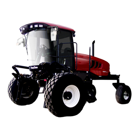
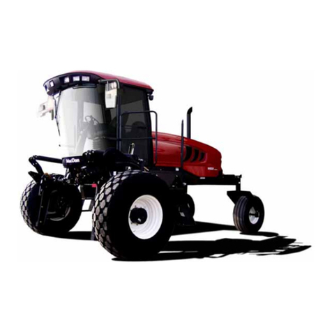
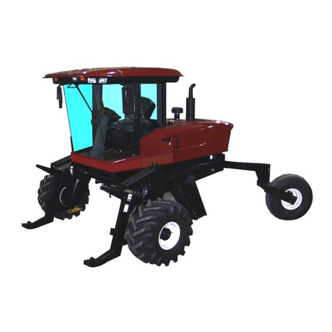
MacDon M155E4 2016 User manual

The harvesting specialists.
M155E4
Self-Propelled Windrower
Unloading and Assembly Instructions (North America)
147764 Revision A
2016 Model Year
Original Instruction

Featuring the Dual Direction®and Ultra Glide®suspension on the M155E4.
Published in October, 2015

Introduction
This instruction manual describes the unloading, setup, and predelivery requirements for the MacDon M155E4
Self-Propelled Windrowers.
Carefully read all the material provided before attempting to unload, assemble, or use the machine.
Retain this instruction for future reference.
Conventions
The following conventions are used in this document: Right- and left-hand are determined from the operator’s
position. The front of the windrower is the side that faces the crop.
NOTE:
Keep your MacDon publications up-to-date. The most current version can be downloaded from our website
(www.macdon.com) or from our Dealer-only site (https://portal.macdon.com) (login required).
147764 iRevision A

List of Revisions
The following list provides an account of major changes from the previous version of this document.
Summary of Change Location
Updated inside front cover illustration to match those
used in other M155E4 manuals and catalogs. Inside Front Cover
Addednotet
o keep MacDon publications up-to-date. Introduction, page i
Revised walking beam bolt torque sequence. 3.3 Repositioning Caster Wheels, page 13
Added note to ensure that there is enough diesel
exhaust fluid (DEF) to avoid DEF level warnings. 3.7 Starting Engine, page 18
Added fuel shut off valve check to starting engine
troubleshooting table. Table 3.1 Troubleshooting, page 19
Added paragraph to recommend selecting a radio with
non-volatile memory in order to retain radio settings
and preset memory.
3.8 Installing AM/FM Radio, page 21
Updated lift cylinder safety prop illustrations to show
red plastic handle. Throughout 3.10 Attaching Headers, page 26
Updated lubrication points illustration to show M155E4
Windrower. 3.11.2 Lubrication Points, page 62
Replaced “Gauges” with “Display Module” in chapter
title. 3.12 Fuel and Diesel Exhaust Fluid (DEF) Display
Module, page 63
Corrected pressure sensor part number from
“MD #5574” to “MD #B5574” in footnote. 4.7.2 Switching the Installed Header Sensors On or
Off, page 108
Added procedure to locate windrower and engine serial
numbers, and updated illustrations. 5.1 Recording Serial Numbers, page 131
Addedsteptocleanfiller cap and surrounding area. 5.5 Checking Hydraulic Oil, page 137
Added description of auto road light feature. 5.11.7 Checking Exterior Lights, page 149
Moved torque specification topics, conversion chart,
and definitions to a new Reference chapter. 6 Reference, page 157
Added and revised terms and acronyms. 6.3 Definitions, page 170
Revisedhazardstatementstobeconsistentwith
current MacDon manuals. Throughout
Revised figure titles. Throughout
147764 ii Revision A

TABLE OF CONTENTS
Introduction...................................................................................................................................... i
List of Revisions ...............................................................................................................................ii
1 Safety.................................................................................................................................................... 1
1.1 Signal Words................................................................................................................................... 1
1.2 General Safety ................................................................................................................................ 2
1.3 Safety Signs.................................................................................................................................... 4
2 Unloading the Windrower...................................................................................................................... 5
2.1 Using Two Forklifts to Unload Windrower .......................................................................................... 5
2.2 Using One Forklift to Unload Windrower............................................................................................7
2.2.1 Method 1: Pulling from Trailer Deck........................................................................................... 7
2.2.2 Method 2: Lifting from Trailer Deck............................................................................................ 8
3 Assembling the Windrower................................................................................................................... 9
3.1 Repositioning Right Leg................................................................................................................... 9
3.2 Installing Drive Wheel .....................................................................................................................11
3.3 Repositioning Caster Wheels.......................................................................................................... 13
3.4 Unpacking Ignition Keys................................................................................................................. 15
3.5 Installing Steps.............................................................................................................................. 16
3.6 Connecting Batteries...................................................................................................................... 17
3.7 Starting Engine.............................................................................................................................. 18
3.8 Installing AM/FM Radio.................................................................................................................. 21
3.9 Installing the Slow Moving Vehicle (SMV) Sign ................................................................................ 25
3.10 Attaching Headers......................................................................................................................... 26
3.10.1 Attaching a D-Series Header................................................................................................... 26
Attaching Header Boots .................................................................................................. 26
Attaching a D-Series Header: Hydraulic Center-Link with Optional Self-Alignment.............. 27
Attaching a D-Series Header: Hydraulic Center-Link without Self-Alignment....................... 32
3.10.2 Attaching an A-Series Header.................................................................................................38
Attaching an A-Series Header: Hydraulic Center-Link with Optional Self-Alignment............. 39
Attaching an A-Series Header: Hydraulic Center-Link without Self-Alignment..................... 44
3.10.3 Attaching an R-Series Header.................................................................................................50
Attaching an R-Series Header: Hydraulic Center-Link with Optional Self-Alignment ............ 50
Attaching an R-Series Header: Hydraulic Center-Link without Self-Alignment..................... 55
3.11 Lubricating the Windrower.............................................................................................................. 61
3.11.1 Lubrication Procedure ............................................................................................................ 61
3.11.2 Lubrication Points................................................................................................................... 62
3.12 Fuel and Diesel Exhaust Fluid (DEF) Display Module....................................................................... 63
4 Cab Display Module (CDM).................................................................................................................. 67
4.1 Cab Display Module (CDM) Programming....................................................................................... 67
4.2 Cab Display Options...................................................................................................................... 69
4.2.1 Setting the Cab Display Language........................................................................................... 69
4.2.2 Changing the Windrower Display Units.................................................................................... 70
4.2.3 Adjusting the Cab Display Buzzer Volume................................................................................ 71
4.2.4 Adjusting the Cab Display Backlighting.................................................................................... 72
4.2.5 Adjusting the Cab Display Contrast ......................................................................................... 73
4.3 Calibrating the Header Sensors...................................................................................................... 75
4.3.1 Calibrating the Header Height Sensor...................................................................................... 75
4.3.2 Calibrating the Header Tilt Sensor........................................................................................... 77
4.3.3 Calibrating the Header Float Sensors ...................................................................................... 79
4.4 Programming the Windrower.......................................................................................................... 81
4.4.1 Activating the Hydraulic Center-Link........................................................................................ 81
4.4.2 Activating the Rotary Header Drive Hydraulics ......................................................................... 81
4.4.3 Setting the Header Knife Speed.............................................................................................. 82
4.4.4 Setting the Knife Overload Speed............................................................................................ 83
147764 iiiRevision A

TABLE OF CONTENTS
4.4.5 Setting the Rotary Disc Overload Speed.................................................................................. 84
4.4.6 Setting the Hydraulic Overload Pressure.................................................................................. 85
4.4.7 Setting the Header Index Mode............................................................................................... 86
4.4.8 Setting the Return to Cut Mode............................................................................................... 87
4.4.9 Setting the Header Cut Width.................................................................................................. 88
4.4.10 Activating the Double Windrow Attachment (DWA)................................................................... 88
4.4.11 Setting the Auto Raise Height .................................................................................................90
4.4.12 Activating the Hay Conditioner ................................................................................................ 91
4.4.13 Displaying Reel Speed ........................................................................................................... 92
4.4.14 Setting the Windrower’s Tire Size............................................................................................ 93
4.4.15 Setting the Engine Intermediate Speed Control (ISC) RPM....................................................... 94
4.4.16 Clearing Sub-Acres................................................................................................................ 95
4.5 Activating Cab Display Lockouts..................................................................................................... 96
4.5.1 Activating Knife Speed Control Lockout................................................................................... 96
4.5.2 Activating Rotary Disc Speed Control Lockout.......................................................................... 97
4.5.3 Activating the Header Float Control Lockout............................................................................. 98
4.5.4 Activating the Draper Speed Control Lockout........................................................................... 99
4.5.5 Activating the Auger Speed Control Lockout ...........................................................................101
4.5.6 Activating the Reel Speed Control Lockout .............................................................................102
4.5.7 Activating the Reel Fore-Aft Control Lockout...........................................................................103
4.5.8 Activating the Header Tilt Control Lockout...............................................................................104
4.6 Displaying Activated Cab Display Lockouts ....................................................................................105
4.7 Troubleshooting Windrower Problems............................................................................................107
4.7.1 Displaying the Windrower and Engine Error Codes..................................................................107
4.7.2 Switching the Installed Header Sensors On or Off ...................................................................108
4.7.3 Displaying Header Sensor Input Signals.................................................................................110
4.7.4 Forcing a Header ID..............................................................................................................111
4.8 Troubleshooting Header Problems.................................................................................................113
4.8.1 Testing the Header Up/Down Activate Function Using the Cab Display Module (CDM) ..............113
4.8.2 Testing the Reel Up/Down Activate Function Using the Cab Display Module (CDM)...................114
4.8.3 Testing the Header Tilt Activate Function Using the Cab Display Module (CDM)........................116
4.8.4 Testing the Reel Fore-Aft Activate Function Using the Cab Display Module (CDM) ....................118
4.8.5 Activating the Hydraulic Purge Using the Cab Display Module (CDM).......................................119
4.8.6 Testing the Knife Drive Circuit Using the Cab Display Module (CDM)........................................121
4.8.7 Testing the Draper Drive Circuit Activate Function Using the Cab Display Module (CDM) ...........123
4.8.8 Testing the Reel Drive Circuit Activate Function Using the Cab Display Module (CDM)..............124
4.8.9 Testing the Rotary Disc Drive Circuit Activate Function Using the Cab Display
Module (CDM)..................................................................................................................126
4.8.10 Testing the Double Windrower Attachment (DWA) Drive Activate Function Using the Cab
Display Module (CDM) ......................................................................................................128
5 Performing Predelivery Checks..........................................................................................................131
5.1 Recording Serial Numbers ............................................................................................................131
5.2 Checking Wheel Drive Lubricant Level...........................................................................................132
5.3 Checking Tire Pressures and Adding Tire Ballast............................................................................133
5.3.1 Checking Tire Pressures........................................................................................................133
5.3.2 Adding Tire Ballast ................................................................................................................133
5.4 Checking Engine Air Intake ...........................................................................................................135
5.5 Checking Hydraulic Oil..................................................................................................................137
5.6 Checking Fuel Separator...............................................................................................................138
5.7 Checking Engine Coolant..............................................................................................................139
5.8 Checking Gearbox Lubricant Level ................................................................................................140
5.9 Checking Air Conditioning (A/C) Compressor Belt...........................................................................141
5.10 Checking Safety System ...............................................................................................................142
5.11 Performing Operational Checks.....................................................................................................144
147764 iv Revision A

TABLE OF CONTENTS
5.11.1 Checking Engine Warning Lights............................................................................................145
5.11.2 Checking Engine Startup.......................................................................................................145
5.11.3 Checking Engine Speed ........................................................................................................146
5.11.4 Checking Gauges and Cab Display Module (CDM) Display on an M155E4...............................146
5.11.5 Checking Electrical System....................................................................................................147
5.11.6 Checking Operator's Presence System...................................................................................147
5.11.7 Checking Exterior Lights........................................................................................................149
Auto Road Light.............................................................................................................151
5.11.8 Checking Horn......................................................................................................................152
5.11.9 Checking Interior Lights.........................................................................................................152
5.11.10 Checking Air Conditioning (A/C) and Heater............................................................................153
5.12 Checking Manuals........................................................................................................................154
5.13 Performing Final Steps..................................................................................................................155
6 Reference...........................................................................................................................................157
6.1 Torque Specifications....................................................................................................................157
6.1.1 SAE Bolt Torque Specifications..............................................................................................157
6.1.2 Metric Bolt Specifications.......................................................................................................159
6.1.3 Metric Bolt Specifications Bolting into Cast Aluminum..............................................................162
6.1.4 Flare-Type Hydraulic Fittings..................................................................................................162
6.1.5 O-Ring Boss (ORB) Hydraulic Fittings (Adjustable)..................................................................164
6.1.6 O-Ring Boss (ORB) Hydraulic Fittings (Non-Adjustable) ..........................................................166
6.1.7 O-Ring Face Seal (ORFS) Hydraulic Fittings...........................................................................167
6.2 Conversion Chart..........................................................................................................................169
6.3 Definitions....................................................................................................................................170
Predelivery Checklist ........................................................................................................................173
147764 vRevision A


1Safety
1.1 Signal Words
Three signal words, DANGER,WARNING,andCAUTION, are used to alert you to hazardous situations. The
appropriate signal word for each situation has been selected using the following guidelines:
DANGER
Indicates an imminently hazardous situation that, if not avoided, will result in death or serious injury.
WARNING
Indicatesapo
tentially hazardous situation that, if not avoided, could result in death or serious injury. It
mayalsobeuse
d to alert against unsafe practices.
CAUTION
Indicates a potentially hazardous situation that, if not avoided, may result in minor or moderate injury. It
may be used to alert against unsafe practices.
147764 1Revision A

SAFETY
1.2 General Safety
CAUTION
The following are general farm safety precautions
that should be part of your operating procedure for
all types of machinery.
Protect yourself.
• When assembling, operating, and servicing machinery,
wear all the protective clothing and personal safety
devices that could be necessary for the job at hand.
Don’t take chances. You may need the following:
• Hard hat
• Protective footwear with slip resistant soles
• Protective glasses or goggles
• Heavy gloves
• Wet weather gear
• Respirator or filter mask
Figure 1.1: Safety Equipment
• Be aware that exposure to loud noises can cause
hearing impairment or loss. Wear suitable hearing
protection devices such as ear muffs or ear plugs to
help protect against objectionable or loud noises.
Figure 1.2: Safety Equipment
•Provideafirst aid kit for use in case of emergencies.
•Keepafire extinguisher on the machine. Be sure the
fire extinguisher is properly maintained. Be familiar with
its proper use.
• Keep young children away from the machinery at
all times.
• Be aware that accidents often happen when the
Operator is tired or in a hurry. Take the time to
consider the safest way. Never ignore the warning
signs of fatigue.
Figure 1.3: Safety Equipment
147764 2Revision A

SAFETY
•Wearclose-fitting clothing and cover long hair. Never
wear dangling items such as scarves or bracelets.
• Keep all shields in place. Never alter or remove safety
equipment. Make sure driveline guards can rotate
independently of the shaft and can telescope freely.
• Use only service and repair parts made or approved by
the equipment manufacturer. Substituted parts may not
meet strength, design, or safety requirements.
Figure 1.4: Safety around Equipment
• Keep hands, feet, clothing, and hair away from moving
parts. Never attempt to clear obstructions or objects
from a machine while the engine is running.
•DoNOT modify the machine. Non-authorized
modifications may impair machine function and/or
safety. It may also shorten the machine’s life.
• To avoid bodily injury or death from unexpected startup
of machine, always stop the engine and remove the
key from ignition before leaving operator’s seat for
any reason.
Figure 1.5: Safety around Equipment
• Keep the service area clean and dry. Wet or oily floors
are slippery. Wet spots can be dangerous when working
with electrical equipment. Be sure all electrical outlets
and tools are properly grounded.
• Keep work area well lit.
• Keep machinery clean. Straw and chaff on a hot
engine is a fire hazard. Do NOT allow oil or grease to
accumulate on service platforms, ladders, or controls.
Clean machines before storage.
• Never use gasoline, naphtha, or any volatile material
for cleaning purposes. These materials may be toxic
and/or flammable.
• When storing machinery, cover sharp or extending
components to prevent injury from accidental contact. Figure 1.6: Safety around Equipment
147764 3Revision A

SAFETY
1.3 Safety Signs
• Keep safety signs clean and legible at all times.
• Replace safety signs that are missing or
become illegible.
• If original parts on which a safety sign was installed are
replaced, be sure the repair part also bears the current
safety sign.
• Safety signs are available from MacDon Parts.
Figure 1.7: Operator’s Manual Decal
147764 4Revision A

2 Unloading the Windrower
You can use one or two forklifts to unload the windrower. Refer to 2.1 Using Two Forklifts to Unload Windrower,
page 5 or 2.2 Using One Forklift to Unload Windrower, page 7.
2.1 Using Two Forklifts to Unload Windrower
Figure 2.1: Two-Forklift Unloading Method
CAUTION
To prevent injury to bystanders and avoid striking them with machinery, do NOT allow people to stand in
the unloading area.
CAUTION
Equipment used for unloading must meet or exceed the specified requirements. Using inadequate
equipment may result in chain breakage, vehicle tipping, or machine damage.
Table 2.1 Lifting Vehicle Requirements
Minimum Lifting Capacity15500 lb. (2500 kg)
Minimum Fork Length 78 in. (1981 mm)
IMPORTANT:
Forklifts are normally rated for a load located 24 in. (610 mm) ahead of the back end of the forks. To obtain forklift
capacity at 48 in. (1220 mm), check with your forklift distributor.
1. Move the trailer onto level ground and block the trailer wheels.
1. At 48 in. (1220 mm) from back end of forks.
147764 5Revision A

UNLOADING THE WINDROWER
2. Set forklift tines to the widest possible setting.
3. Position one forklift on either side of the trailer, and position the forks under the windrower frame.
NOTE:
The windrower’s center of gravity is approximately 55 in. (1397 mm) rearwards from the center of the
drive wheel.
4. Lift with both forklifts simultaneously until the windrower is clear of the trailer deck.
WARNING
Ensure the forks are secure before moving the trailer away from the load. Stand clear when lifting.
5. Drive truck slowly forward until trailer deck is clear of windrower.
6. Lower unit slowly to the ground using both forklifts simultaneously. If the ground is soft, place wooden blocks
under the front shipping stands.
7. Back off forklifts.
8. Check windrower for shipping damage, and check shipment for missing parts.
147764 6Revision A

UNLOADING THE WINDROWER
2.2 Using One Forklift to Unload Windrower
There are two different methods for unloading a windrower using one forklift. If using a chain to pull the windrower
to a ground level that is equal to, or slightly lower than, the height of the trailer deck, refer to 2.2.1 Method 1: Pulling
from Trailer Deck, page 7. If lifting the windrower from the left or right side of the trailer deck, refer to 2.2.2 Method
2: Lifting from Trailer Deck, page 8.
2.2.1 Method 1: Pulling from Trailer Deck
CAUTION
Equipment used for unloading must meet or exceed the specified requirements. Using inadequate
equipment may result in chain breakage, vehicle tipping, or machine damage.
Table 2.2 Lifting Vehicle Requirements
Minimum Capacity25500 lb. (2500 kg)
IMPORTANT:
Forklifts are normally rated for a load located 24 in. (610 mm) ahead of the back end of the forks. To obtain forklift
capacity at 48 in. (1220 mm), check with your forklift distributor.
Table 2.3 Pulling Chain Requirements
Type Overhead lifting quality (1/2 in.)
Minimum Working Load 5000 lb. (2270 kg)
1. Position the rear of the trailer against an unloading
dock that is the same height, or slightly lower than, the
trailer deck.
2. Remove shipped parts from underneath the
windrower frame.
3. Set forklift tines to the widest possible setting.
4. Drive forklift up to the rear of the windrower and place
forks under the rear frame cross member.
5. Install chains between the forklift mast and the jacking
brackets on both front legs of the windrower. Chains
must be the same length.
Figure 2.2: Chain Installation Location
CAUTION
The front legs rest on the trailer deck on skid shoes. Ensure there are no obstructions preventing the skid
shoes from sliding rearwards, and watch carefully while dragging the unit to ensure the skid shoes do not
slide sideways towards the edge of the trailer deck.
6. Drag the windrower rearwards off of carrier.
7. Remove chains and back off the forklift.
8. Check windrower for shipping damage, and check shipment for missing parts.
2. At 48 in. (1220 mm) from back end of forks.
147764 7Revision A

UNLOADING THE WINDROWER
2.2.2 Method 2: Lifting from Trailer Deck
CAUTION
Equipment used for unloading must meet or exceed the specified requirements. Using inadequate
equipment may result in chain breakage, vehicle tipping, or machine damage.
Table 2.4 Lifting Vehicle Requirements
Minimum Capacity311,000 lb. (4994 kg)
Minimum Fork Length 78 in. (1981 mm)
IMPORTANT:
Forklifts are normally rated for a load located 24 in. (610 mm) ahead of the back end of the forks. To obtain forklift
capacity at 48 in. (1220 mm), check with your forklift distributor.
WARNING
Ensure the forks are secure before moving the trailer away from the load. Stand clear when lifting.
1. Move the trailer onto level ground and block the
trailer wheels.
2. Set forklift tines to the widest possible setting.
3. Position forklift on left or right side of trailer, and
position forks (A) under windrower frame.
NOTE:
The windrower’s center of gravity is
approximately 55 in. (1397 mm) rearwards from
the center of the drive wheel.
Figure 2.3: Windrowers on Trailer
WARNING
Ensure the forks extend beyond the far side of the frame.
4. Lift until windrower is clear of the trailer deck.
5. Back forklift slowly away from trailer until the windrower is clear of the trailer deck.
6. Lower unit slowly to the ground. If the ground is soft, place wooden blocks under the front shipping stands.
7. Back off forklift.
8. Check windrower for shipping damage, and check shipment for missing parts.
3. At 48 in. (1220 mm) from back end of forks.
147764 8Revision A

3 Assembling the Windrower
Perform all procedures in this chapter in the order in which they are listed.
3.1 Repositioning Right Leg
The right cab-forward leg requires repositioning from shipping to field configuration.
1. Support the front of the windrower with a stand (A) (or
equivalent) so the right leg is off the ground.
2. Position jack (B) under the right leg and slightly raise
thejacktotakesomeweightofftheleg.
Figure 3.1: Right Leg
3. Remove two bolts (A), washers, and nuts from frame.
Figure 3.2: Windrower Frame
4. Adjust jack height until pin (A) is loose. Extract pin by
tapping out with a hammer or using tool (MD #B5442).
IMPORTANT:
Removing the pins will be difficult if the jack is not
properly positioned to take the weight off the leg.
Figure 3.3: Windrower Frame
147764 9Revision A

ASSEMBLING THE WINDROWER
5. Removesecondpin(A)usingaslidehammerand
special welded nut and washer to fit in front of Diesel
Exhaust Fluid (DEF) tank.
NOTE:
Second pin (A) must be tapped forward and
extracted through the front of the frame due to
the position of the DEF tank.
Figure 3.4: Windrower Frame
6. Move leg outwards to expose one hole (A).
7. Reinstall pins and secure with bolts (B), washers, and
nuts. Torque nuts to 100 ft·lbf (136 N·m).
8. Lower jack and remove it from the right-hand leg.
Figure 3.5: Windrower Frame
147764 10 Revision A

ASSEMBLING THE WINDROWER
3.2 Installing Drive Wheel
1. Support the front of the windrower off the ground using
stand (A).
Figure 3.6: Windrower on Stand
2. Position drive wheel (A) against the wheel drive
hub (B) so the air valve (C) is on the outside and the
tire tread (D) points in cab-forward direction.
NOTE:
For turf tires (diamond tread), be sure arrow on
sidewall points in cab-forward rotation.
3. Lift wheel onto hub using a lifting device.
4. Lower lifting device.
Figure 3.7: Drive Wheel
147764 11 Revision A

ASSEMBLING THE WINDROWER
5. Line up the holes in the rim with the studs on the wheel
drive hub and install wheel nuts (A).
IMPORTANT:
To avoid damage to wheel rims and studs,
tighten nuts by hand. Do NOT useanimpact
gun, do NOT use lubricant or Never-Seez®
compound, and do NOT overtighten wheel nuts.
6. Torque drive wheel nuts to 375 ft·lbf (510 N·m) using
the tightening sequence shown.
IMPORTANT:
Use only manufacturer specified nuts
(MD #205397).
7. Repeat tightening sequence two additional times
ensuring the specified torque of 375 ft·lbf (510 N·m) is
achieved each time.
8. Repeat torque procedure every hour until two
consecutive checks confirm there is no movement of
the nuts.
Figure 3.8: Drive Wheel Nuts
147764 12 Revision A
Table of contents
Other MacDon Tractor manuals

MacDon
MacDon M205 User manual

MacDon
MacDon M Series User manual

MacDon
MacDon M150 2009 Parts list manual

MacDon
MacDon M155 User manual

MacDon
MacDon M1170 User manual

MacDon
MacDon M150 User manual

MacDon
MacDon M105 User manual

MacDon
MacDon M2170NT User manual

MacDon
MacDon M150 User manual

MacDon
MacDon 9250 User manual