Pulled to the left and rearward from its neutral
position,
it
determines
the reverse speed.
Tractor
speed in
either
direction
may be
increased
or
decreased at any time
with
or
without
the use of the
motion
control
pedal.
8. TRANSAXLE
SHIFT
LEVER
Use
this
lever to
select the transaxle speed range you wish to use.
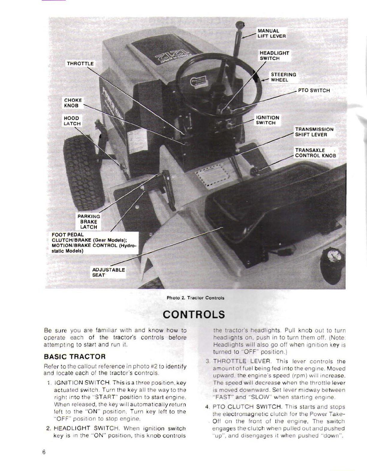
5.
CHOKE
KNOB.
By cable extension this
knob
can
rols
he
uel-air
mixture
in the engine's
carbure:or.
The
knob
should
be pulled
out
when
--a1
the
engine
and then pushed in
shortly
a::er
engine
begins
to run.
-. STEERING WHEEL.
Controls
the
front
wheels
of
the
tractor
for
steering.
7.
TRANSMISSION
SHIFT LEVER. In
conjunction
with
throttle
and transax/e settings, this lever
determines
the
direction
and speed the
tractor
will move
over
the
ground.
Hi
N
Lo
Shift
Pattern
-
Gear
Models
Transaxle
Shift
Pattern
Moved to the
right
into
the
"LO"
position
the
transaxle will
operate
in
its
low
speed range.
Moved to the
left
into
the
"HI"
position
the
transaxle will
allow
the
tractor
to
move
in its
highest
speed
ranges.
(Note:
while
not
recommended,
this
lever must be in the
"neutral"
position
to
keep
the
engine
running
when the
operator
leaves the seat.)
9.
BRAKE/CLUTCH
PEDAL
(Gear Models). A
th
ree
function,
foot
operated
control,
this
pedal,
when depressed
halfway
down,
disengages the
drive train
clutch
allowing
for
a
gear
change
with
the transmission lever. Depressing
the
pedal all
the
way
down
activates
the
two
pressure padson
the
disc
brake,
stopping
the
forward
or
rearward
motion
of
the tractor.
10.
MOTION
CONTROL
PEDAL
(Hydrostatic
Models). When fUlly depressed,
this
foot
operated
control
also activates the pressure
pads on the disc brake,
stopping
the
tractor.
As
the pedal is raised, it releases the brakes and
begins to activate
the
hydrostatic
transmission
linkage
putting
the
tractor
in
motion
in the
direction
set
by
the
transmission
shift
lever. As
the pedal is released fully, the
tractor
will
accelerate
up
to
and
hold
the
speed established
by
the
transmission
shift
lever setting.
11.
PARKING
BRAKE
LATCH.
Once
the
foot
pedal
is
fully
depressed, a
slight
additional
rotating
action
with
the
operator's
toecauses
this
latch to
hook
over arod
on
the frame
of
the tractor.
Properly adjusted.
this
keeps the
brake
pads
locked
on the
disc
and
prevents the
tractor
from
moving.
12.
HOOD
LATCH.
Retains the
lower
edges of the
hood preventing
bounce
on
rough
terrain.
13.
ADJUSTABLE
SEAT.
Contoured
seat may be
moved
forward
or
rearward
up
to
3"
in 1"
increments.
Tilt
seat
forward
and remove
quick
change
keys and pins.
Slide
seat assembly back
or
forth so that
hole
lines
up
with
one
in seat
bracket. Reinsert pin
and
quick
change
key.
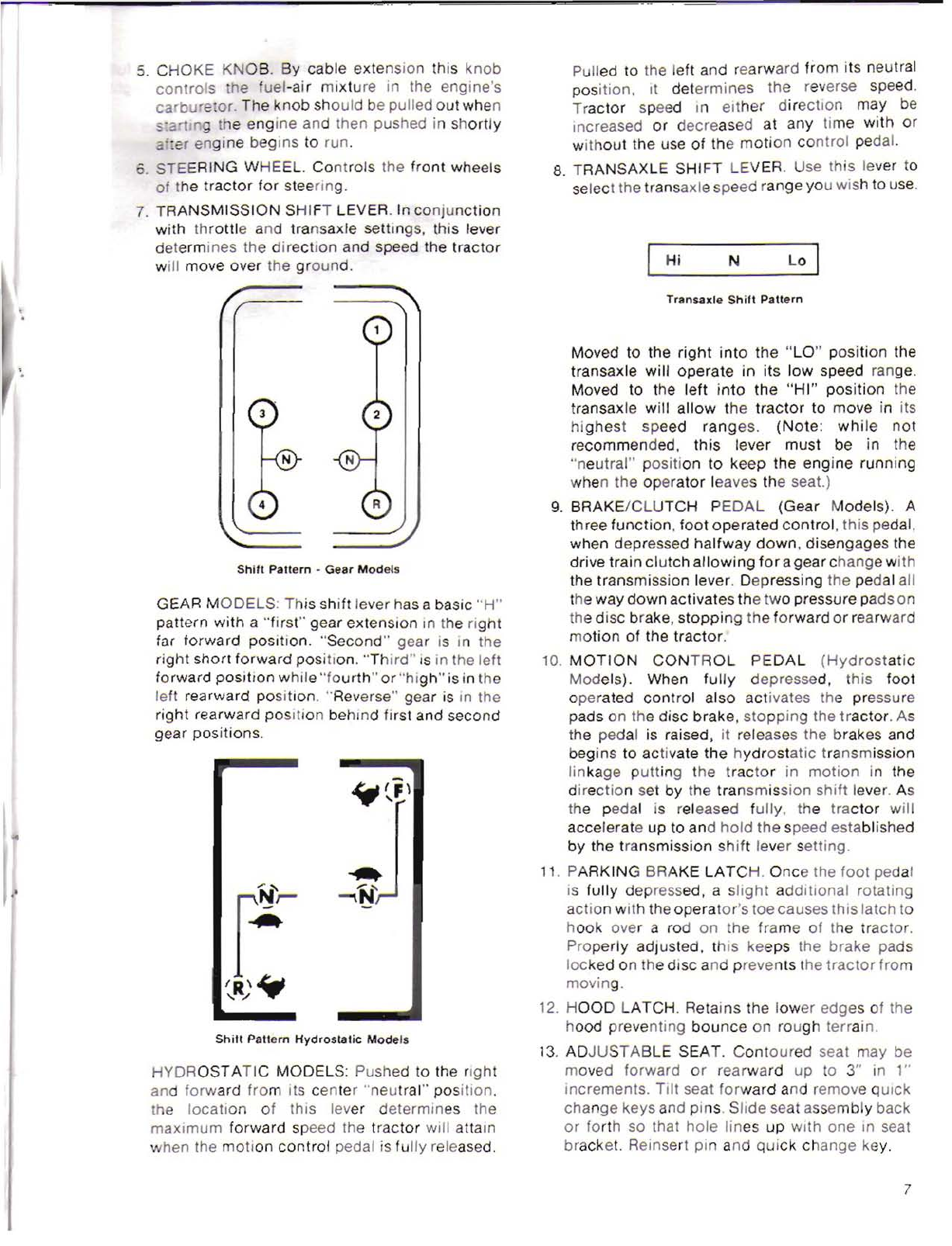
N
Shift
Pallern
Hydrostatic
Models
HYDROST
ATIC
MODELS: Pushed to the right
and
forward
from
its
center
"neutral"
position.
the
location
of
this lever
determines
the
maximum
forward
speed the
tractor
will attain
hen the
motion
control
pedal is
fully
released.
GEAR
MODELS:
This
shift
lever has abasic
"H"
pattern
with
a
"first"
gear
extension
in the
right
far
forward
position.
"Second"
gear is in the
right
short
forward
position.
"Third"
is in the left
forward
position
while
"fourth"
or
"high"
is in the
left rearward
position.
"Reverse" gear is in the
right
rearward
position
behind
first and second
gear
positions.
7