Machine Support Vibracon SM12CS User manual

Version 2.3, May 2009, © Machine Support B.V. Vibracon®manual
www.machinesupport.com
An SKF Group Company
Vibracon®manual
ООО "Индастриал Партнер"
Авторизованный дистрибьютор SKF
www.skf.indpart.ru
8(495)223-07-69
Техническая поддержка:
[email protected], 8(495)223-07-69

Version 2.3, May 2009, © Machine Support B.V. Vibracon®manual
www.machinesupport.com
Contents
Version
Chapter 1 Vibracon®Brochure 9
Chapter 2 How to order Vibracon®chocks 2.1
Chapter 3 Vibracon®References and Approvals 2.3
Chapter 4 Vibracon®Installation Procedure 2
Chapter 5 Vibracon®Frequently Asked Questions 2
Chapter 6 Vibracon® Application Design Instructions 2.1
Chapter 7 Other products and services of the Machine Support Group 2
ООО "Индастриал Партнер"
Авторизованный дистрибьютор SKF
www.skf.indpart.ru
8(495)223-07-69
Техническая поддержка:
[email protected], 8(495)223-07-69

Version 2.3, May 2009, © Machine Support B.V. Vibracon®manual
www.machinesupport.com
Introduction
Vibracon®chocks are permanent, strong and re-usable machinery mounting chocks for all
types of rotating or critically aligned machinery. Vibracon®chocks are mechanically stiff
chocks that make accurate mounting simple and quick. The Vibracon®advantages are
elimination of the trial and error alignment process characteristic for the “mill and shim”
method and adjustability during the life cycle of the machinery.
The Vibracon®chock has many configurations and material options to satisfy technical
concerns, in end user environments and production line costs. All Vibracon®chocks include
the spherical top plate and mating middle section. This self leveling configuration
accommodates the angular differences that are inherent with mounting surfaces. The height
adjustment feature has the greatest range in the industry, which makes the Vibracon®chock
easy to install.
Vibracon®chocks are the most economical means to establish a perfect mounting plane. The
Vibracon®advantage is the capability to perfectly create the mounting plane within minutes
and repeatedly for Production or Service Managers and Accountants.
In this manual we will inform you about all facts of the Vibracon®. If you have further
questions or if you need additional information, please remember The Machine Support
Group is a 24/7 organization. Please don’t hesitate to contact one of our offices as
mentioned below.
Machine Support B.V. Machine Support, Inc.
Kaartenmakerstraat 7 109B 86th street
NL-2984 CB Ridderkerk Virginia Beach, VA 23451
The Netherlands United States
Phone (+) 31 (0)180 483828 Phone (+) 1 877 621 1777
Fax (+) 31 (0)180 483829 (+) 1 757 417 7411
Machine Support, Inc. Machine Support, Inc.
2 Redland Place 218 Venture Blvd.
The Woodlands, TX 77382 Houma, LA 70360
United States United States
Phone (+) 1 281 298 5001 Phone (+) 1 985 851 5100
Fax (+) 1 281 657 7597 Fax (+) 1 985 851 0061
Machine Support U.A.E. Machine Support Singapore
P.O. Box 8807 16 Tuas Avenue 10
Dubai Singapore 639140
United Arab Emirates Singapore
Phone (+) 971 (0) 433 92215 Phone (+) 65 6861 0484
Fax (+) 971 (0) 433 91952 Fax (+) 65 6861 0191
ООО "Индастриал Партнер"
Авторизованный дистрибьютор SKF
www.skf.indpart.ru
8(495)223-07-69
Техническая поддержка:
[email protected], 8(495)223-07-69

Version 2.1, August 2005, © Machine Support B.V. page 1 of 16 Vibracon®manual, chapter 2
www.machinesupport.com
An SKF Group Company
How to order Vibracon®chocks
ООО "Индастриал Партнер"
Авторизованный дистрибьютор SKF
www.skf.indpart.ru
8(495)223-07-69
Техническая поддержка:
[email protected], 8(495)223-07-69

Version 2.1, August 2005, © Machine Support B.V. page 2 of 16 Vibracon®manual, chapter 2
www.machinesupport.com
2 How to order Vibracon®chocks
2.1 HOW TO SELECT THE RIGHT VIBRACON®CHOCK SIZE?...............................3
2.2 HOW TO GET A VIBRACON®CHOCKING PROPOSAL FREE OF CHARGE?........3
2.3 HOW TO ORDER VIBRACON®CHOCKS?.....................................................4
2.3.1 The Original...........................................................................................................4
2.3.1.1 Article numbers Vibracon®Original chocks.......................................................5
2.3.2 The Low Profile......................................................................................................5
2.3.2.1 Article numbers Vibracon®Low Profile chocks .................................................6
2.3.3 The extended Vibracon®Original and Low Profile.................................................6
2.3.3.1 Article numbers Vibracon®additional bottom rings...........................................7
APPENDIX 1 DATA SHEETS FOR VIBRACON®CALCULATION
APPENDIX 2 EXAMPLE OF CHOCKING PROPOSAL
ООО "Индастриал Партнер"
Авторизованный дистрибьютор SKF
www.skf.indpart.ru
8(495)223-07-69
Техническая поддержка:
[email protected], 8(495)223-07-69

Version 2.1, August 2005, © Machine Support B.V. page 3 of 16 Vibracon®manual, chapter 2
www.machinesupport.com
2.1 How to select the right Vibracon®chock size?
To get an indication which size of Vibracon®should be used, the following parameters will
give you an impression:
•What is the size of the bolthole in the component bed plate?
•What is the minimum distance (pitch) between two adjacent holes?
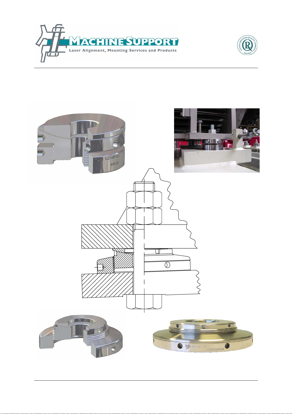
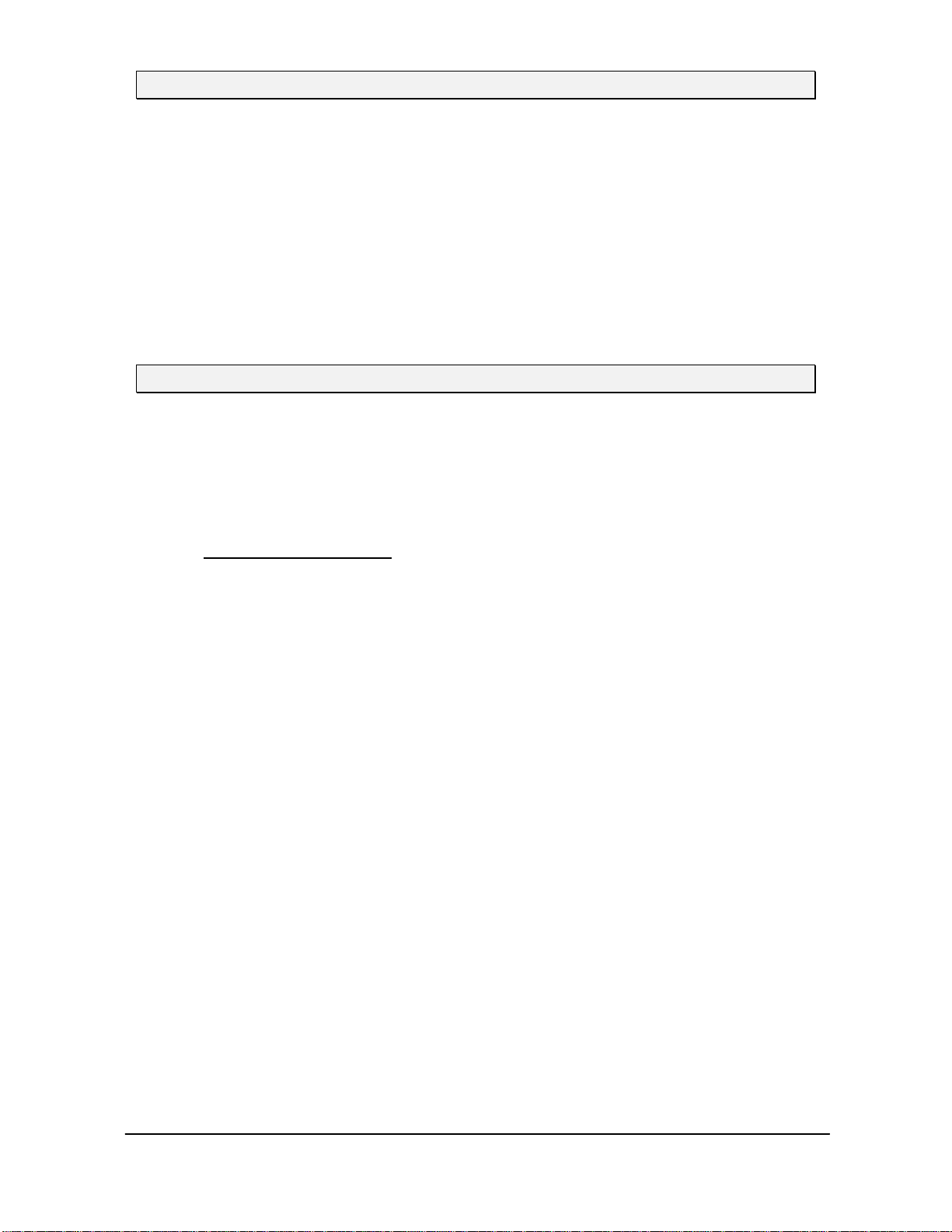
The type indication of Vibracon®is related to the foundation bolts for which they can be used.
For instance the Vibracon®SM30 is developed to be used in combination with a hexagonal
bolt M30 but it is also possible to use one size of bolt diameter bigger, in this example a bolt
M33.
2.2 How to get a Vibracon®chocking proposal free of charge?
As a part of our service, Machine Support offers you a free of charge calculation proposal for
the mounting of your component. To prepare this calculation we need information concerning
the component, the available chocking height and some information concerning the
foundation.
The fastest way to receive a chocking proposal for your application is to fill out one of the
appropriate datasheets (APPENDIX 1). The datasheets can also be downloaded from our
website www.machinesupport.com we ask you to send the completed datasheets by e-mail
to:
The used calculation software is approved by the Classification Societies involved for marine
applications. On request Machine Support will make contact with the OEM to support you
with getting an agreement on the chocking proposal.
Normally you will receive, within one day, a calculation as mentioned in APPENDIX 2.
A full proposal consists of four sheets:
•Report of all information related to the selection of the chock, including operating
forces on the chocks plus foundation hardware information;
•Illustration of the top view of the component that shows the location of the chocks, the
position of the positioning and / or collision chocks and the fitted bolts (if required);
•Illustration of the cross section of the foundation bolt in which the clamping length and
foundation bolt are specified;
•Illustration of the cross section of the fitted bolt, if required, in which the clamping
length and fitted bolt are specified.
Machine Support, upon request, will submit our report to the involved Classification Society
for approval. Costs for this service are on an as negotiated and per event basis.
ООО "Индастриал Партнер"
Авторизованный дистрибьютор SKF
www.skf.indpart.ru
8(495)223-07-69
Техническая поддержка:
[email protected], 8(495)223-07-69

Version 2.1, August 2005, © Machine Support B.V. page 4 of 16 Vibracon®manual, chapter 2
www.machinesupport.com
2.3 How to order Vibracon®chocks?
In the Vibracon®brochure (see chapter 1) you will find an overview of the standard elements.
If you have a specific component which has to be chocked and the standard elements will
not fit, please don’t hesitate to send in your demands and we will find out if we can provide
you a proper solution.
Based on the unique article numbers the chocks can be ordered by fax, mail or e-mail. As
soon as we have received your order we will send you an order conformation in reply.
Vibracon®chocks are always on stock at Machine Support in the Netherlands. However, it is
recommended to check the delivery time before ordering. Our local dealers of the elements
also have some elements on stock.
A list of all distributors is available on the website from Machine Support:
www.machinesupport.com
2.3.1 The Original
Vibracon® SM chocks are machinery mounting chocks that are easily and accurately
adjusted. The chocks accommodate up to a 4° angular difference between machine and the
mounting base without expensive machining of the base or extra work of installing epoxy
resin chocks.
The self levelling capability combined with the height adjustment feature eliminates the
possibility of a soft foot in the production line and for the life cycle of the machinery.
Figure 2.3.1 Vibracon®Original
ООО "Индастриал Партнер"
Авторизованный дистрибьютор SKF
www.skf.indpart.ru
8(495)223-07-69
Техническая поддержка:
[email protected], 8(495)223-07-69

Version 2.1, August 2005, © Machine Support B.V. page 5 of 16 Vibracon®manual, chapter 2
www.machinesupport.com
2.3.1.1 Article numbers Vibracon®Original chocks
The article numbers of the different sizes of chocks are as follows:
Material DIN 1.1191 Material DIN 1.4404 ( AISI 316L )
SM12CS SM12SS
SM16CS SM16SS
SM20CS SM20SS
SM24CS SM24SS
SM30CS SM30SS
SM36CS SM36SS
SM42CS SM42SS
SM48CS SM48SS
SM56CS SM56SS
SM64CS SM64SS
Figure 2.3.1.1 Article numbers Original Vibracon®chocks
2.3.2 The Low Profile
The Low Profile chocks offer an economic solution for repair projects or fixed design systems
where expensive milled chocks, shims or epoxy resins were applied. The Vibracon®SM Low
Profile configuration addresses those applications where the chock height between the
foundation and component has been established by the previous design. Most of the other
chocking methods are time consuming and do not support the life cycle needs of the
machine owners and installation activities on a tight schedule. A variety of adjustment tools
for confined installation spaces is available.
Figure 2.3.2 Vibracon®Low Profile
ООО "Индастриал Партнер"
Авторизованный дистрибьютор SKF
www.skf.indpart.ru
8(495)223-07-69
Техническая поддержка:
[email protected], 8(495)223-07-69

Version 2.1, August 2005, © Machine Support B.V. page 6 of 16 Vibracon®manual, chapter 2
www.machinesupport.com
2.3.2.1 Article numbers Vibracon®Low Profile chocks
The article numbers of the different sizes of chocks are as follows:
Material DIN 1.7225
( other materials on request)
SM12LP
SM16LP
SM20LP
SM24LP
SM30LP
SM36LP
SM42LP
Figure 2.3.2.1 Article numbers Vibracon®Low Profile chocks
2.3.3 The extended Vibracon®Original and Low Profile
It can happen that the maximum element height is not sufficient to fill up the gap between the
foundation top plate and the bed plate of the component. In that situation it is possible to
introduce a so called additional bottom ring to extend the maximum height of the Vibracon®
Original and Low Profile chocks. This ring will be mounted between the base plate of the
chock and the top plate of the foundation. As an alternative for the additional bottom ring
Machine Support can also provide Vibracon®extended bottom rings.
As a rule of thumb, the height of the chocks should not exceed the diameter of the elements.
For instance the maximum height of a Vibracon®SM30, with a diameter of 140 mm, should
not exceed a chock height of 140 mm.
Figure 2.3.3.1 SM element with additional Figure 2.3.3.2 SM - LP element with
bottom ring additional bottom ring
ООО "Индастриал Партнер"
Авторизованный дистрибьютор SKF
www.skf.indpart.ru
8(495)223-07-69
Техническая поддержка:
[email protected], 8(495)223-07-69

Version 2.1, August 2005, © Machine Support B.V. page 7 of 16 Vibracon®manual, chapter 2
www.machinesupport.com
2.3.3.1 Article numbers Vibracon®additional bottom rings
The article numbers of the additional bottom rings are as follows:
Material: DIN 1.0570 / 1.1191
Article no. Height
additional ring Max. extended
height (D) SM element Max. extended height (D)
SM - LP element
SM12EV 22 mm 60 mm Not available
SM16EV 35 mm 80 mm 65 mm
SM20EV 50 mm 100 mm 80 mm
SM24EV 63 mm 120 mm 93 mm
SM30EV 78 mm 140 mm 108 mm
SM36EV 93 mm 160 mm 133 mm
SM42EV 118 mm 190 mm 163 mm
SM48EV 135 mm 220 mm Not available
SM56EV 140 mm 230 mm Not available
SM64EV 155 mm 250 mm Not available
Figure 2.3.3.1 Article numbers Vibracon®additional bottom rings
ООО "Индастриал Партнер"
Авторизованный дистрибьютор SKF
www.skf.indpart.ru
8(495)223-07-69
Техническая поддержка:
[email protected], 8(495)223-07-69

Version 2.1, August 2005, © Machine Support B.V. page 8 of 16 Vibracon®manual, chapter 2
www.machinesupport.com
APPENDIX 1
DATASHEET FOR VIBRACON CALCULATION
ООО "Индастриал Партнер"
Авторизованный дистрибьютор SKF
www.skf.indpart.ru
8(495)223-07-69
Техническая поддержка:
[email protected], 8(495)223-07-69

Version 2.1, August 2005, © Machine Support B.V. page 9 of 16 Vibracon®manual, chapter 2
www.machinesupport.com
Machine Support B.V., The Netherlands
Phone : +31 (0)180 483828
Fax : +31 (0)180 483829
Website :
www.machinesupport.com
Please insert data into coloured cells
Shipyard / Customer :
Shipname / Project :
Classification society :
Object :
Make / type :
Engine Mass : (kg)
Power : (kW)
Revolutions : (rpm)
Number of elements : (-)
Foundation bolthole diameter : (mm)
Fitted bolthole diameter : (mm)
Top View of engine LEGEND
Total length of the component : (mm)
A
Location first hole (seen from coupling) : (mm) B
Pitch between other holes (on one side) : (mm) C
Total width of the component : (mm) D
Pitch of boltholes (left to right) : (mm) E
Foundation width (inside) : (mm) F
Cross section of mounting detail LEGEND
Top sleeve length :(mm) G
Bed plate thickness :(mm) H
Chock height : (mm) J
Top plate thickness : (mm) K
Bottom sleeve length : (mm) L
Address information
Company :
Contact :
Phone :
Fax :
E-mail :
MS-F-333 REV. 04 D.D. 03.05.2005
Remarks:
Selection of Vibracon SM element for Diesel/Gas/Turbine Engines
Stopper clearance in accordance
with manufacturer instructions
Steel side chocks
COUPLING
FED
BA
C
G
H
J
K
L
ООО "Индастриал Партнер"
Авторизованный дистрибьютор SKF
www.skf.indpart.ru
8(495)223-07-69
Техническая поддержка:
[email protected], 8(495)223-07-69

Version 2.1, August 2005, © Machine Support B.V. page 10 of 16 Vibracon®manual, chapter 2
www.machinesupport.com
Machine Support B.V., The Netherlands
Phone : +31 (0)180 483828
Fax : +31 (0)180 483829
Website :
www.machinesupport.com
Please insert data into coloured cells
Shipyard / Customer :
Shipname / Project :
Classification society :
Object :
Make / type :
Gearbox Mass : (kg)
Power : (kW)
Revolutions : (rpm)
Number of elements : (-)
Foundation bolthole diameter : (mm)
Fitted bolthole diameter : (mm)
Reduction rate : (-)
Average distance of boltholes : (mm)
Distance between centre line of shaft and top plate : (mm)
Propulsion efficiency : (N/kW)
(For and aft chocks capable of transmitting 3 times nominal propeller thrust must be installed)
Top View of gearbox LEGEND
Total length of gearbox : (mm)
A
Location first hole (seen from coupling) : (mm) B
Pitch between other holes (on one side) : (mm) C
Total width of gearbox : (mm) D
Pitch of boltholes (left to right) : (mm) E
Foundation width (inside) : (mm) F
Cross section of mounting detail LEGEND
Top sleeve length :(mm) G
Bed plate thickness :(mm) H
Chock height : (mm) J
Top plate thickness : (mm) K
Bottom sleeve length : (mm) L
Address information
Company :
Contact :
Phone :
Fax :
E-mail :
MS-F-332 REV. 04 D.D. 03.05.2005
Remarks:
Selection of Vibracon SM element for (Marine) Gearboxes
COUPLING
C B
A
FED
G
H
J
K
L
ООО "Индастриал Партнер"
Авторизованный дистрибьютор SKF
www.skf.indpart.ru
8(495)223-07-69
Техническая поддержка:
[email protected], 8(495)223-07-69

Version 2.1, August 2005, © Machine Support B.V. page 11 of 16 Vibracon®manual, chapter 2
www.machinesupport.com
Machine Support B.V., The Netherlands
Phone : +31 (0)180 483828
Fax : +31 (0)180 483829
Website :
www.machinesupport.com
Please insert data into the coloured cells
Shipyard / Customer :
Shipname / Project :
Classification society :
Object :
Make / type :
Generator Mass : (kg)
Power : (kW)
Revolutions : (rpm)
Number of elements : (-)
Foundation bolthole diameter : (mm)
Fitted bolthole diameter : (mm)
Top View of generator LEGEND
Total length of generator : (mm)
A
Location first hole (seen from coupling) : (mm) B
Pitch between other holes (on one side) : (mm) C
Total width of the component : (mm) D
Pitch of boltholes (left to right) : (mm) E
Foundation width (inside) : (mm) F
Foot length : (mm) M
Cross section of mounting detail LEGEND
Top sleeve length :(mm) G
Bed plate thickness :(mm) H
Chock height : (mm) J
Top plate thickness : (mm) K
Bottom sleeve length : (mm) L
Address information
Company :
Contact :
Phone :
Fax :
E-mail :
MS-F-334 REV. 04 D.D. 03.05.2005
Remarks:
Selection of Vibracon SM element for Generators/E-motors/Pumps/Comp.
COUPLING
COUPLING
FDEFED
A
CB A
BMM
C
G
H
J
K
L
ООО "Индастриал Партнер"
Авторизованный дистрибьютор SKF
www.skf.indpart.ru
8(495)223-07-69
Техническая поддержка:
[email protected], 8(495)223-07-69

Version 2.1, August 2005, © Machine Support B.V. page 12 of 16 Vibracon®manual, chapter 2
www.machinesupport.com
APPENDIX 2
EXAMPLE OF CHOCKING PROPOSAL
ООО "Индастриал Партнер"
Авторизованный дистрибьютор SKF
www.skf.indpart.ru
8(495)223-07-69
Техническая поддержка:
[email protected], 8(495)223-07-69

Version 2.1, August 2005, © Machine Support B.V. page 13 of 16 Vibracon®manual, chapter 2
www.machinesupport.com
Phone :
Fax :
Website :
E-mail :
Shipyard / Customer :
Shipname / Project : C-factor
Classification society : Det Norske Veritas 5000
Object : Piston engine
Make / type :
Machine
Mass (if engine with water +oil) : 37500 (kg)
Power : 2880 (kW)
Revolutions : 600 (rpm)
Foundation width (bolt distance) : 1400 (mm)
Number of elements : 18 (-)
Bolthole diameter : 35 (mm)
Correction / Safety factor : 2 (-)
Minimum required Vibracon SM element : 30 (-)
Advised Vibracon SM element :30 (-)
Element load (maximum) : 24,05 (kN)
Element load (minimum) : 16,78 (kN)
Machine load : 48,11 (kN)
:
Foundation bolts : 14 * M30 (L =420 mm) (-)
Material : grade 8.8 (-)
E-modul : 207000 (N/mm²)
Yield strength : 630 (N/mm²)
Elongation foundation bolt : 0,62 (mm)
Tension per bolt : 243,3 (kN)
Tensile stress : 468,7 (N/mm²)
Disposable yield strength : 74 (%)
Equivalent stress : 552,0 (N/mm²)
Disposable yield strength < 90 % : 88 (%)
Tightening torque : 1460 (Nm)
:
Fitted bolts : 4 * M30 (L =462 mm) (-)
Material : 42 CrMo 4 (-)
E-modul : 207000 (N/mm²)
Yield strength : 750 (N/mm²)
Elongation of fitted bolt : 0,57 (mm)
Tension per bolt : 243,3 (kN)
Tensile stress : 468,7 (N/mm²)
Disposable yield strength : 62 (%)
Equivalent stress : 552,0 (N/mm²)
Disposable yield strength < 90% : 74 (%)
Tightening torque : 1460 (Nm)
MS-F-331 BLAD 1/1 REV.00 D.D. 01.08.2001 REV. 27
MS REF. NUMBER : NE-04-0155-01-PW
Foundation bolt
Fitted stud bolt
Baldvin NC-100
Selection of Vibracon SM element
Calculation of holding down bolts' torque
MaK 6M32
Slippstödin ehf
+31 (0)180 483828
+31 (0)180 483829
www.machinesupport.com
Machine Support B.V., The Netherlands
ООО "Индастриал Партнер"
Авторизованный дистрибьютор SKF
www.skf.indpart.ru
8(495)223-07-69
Техническая поддержка:
[email protected], 8(495)223-07-69

Version 2.1, August 2005, © Machine Support B.V. page 14 of 16 Vibracon®manual, chapter 2
www.machinesupport.com
ООО "Индастриал Партнер"
Авторизованный дистрибьютор SKF
www.skf.indpart.ru
8(495)223-07-69
Техническая поддержка:
[email protected], 8(495)223-07-69

Version 2.1, August 2005, © Machine Support B.V. page 15 of 16 Vibracon®manual, chapter 2
www.machinesupport.com
xM30 3,5 Root diameter 25,71
Sleeve Ø32 - Ø60
Bed plate
Top plate
SW30 (Spherical Washer)
+31 (0)180 483828
+31 (0)180 483829
www.machinesupport.com
info@machinesupport.comE-mail
Website
Fax
Phone
Machine Support B.V. The Netherlands
APPROVAL
SKETCH
:
:
:
:
:
:
:
:
:
:
Calculations are valid for bolts with ISO Metric screw thread and coarse pitch, minimum material grade 8.8, yieldstrength> 630 N/mm², oil lubricated thread courses
and nut mating surfaces without slide additives.
MS-F-336 BLAD 1/1 REV.00 D.D. 01.08.2001
NE-04-0155-01-PWMS REF. NUMBER:
ООО "Индастриал Партнер"
Авторизованный дистрибьютор SKF
www.skf.indpart.ru
8(495)223-07-69
Техническая поддержка:
[email protected], 8(495)223-07-69

Version 2.1, August 2005, © Machine Support B.V. page 16 of 16 Vibracon®manual, chapter 2
www.machinesupport.com
Bed plate
Top plate
x
M30 3,5 Root diameter 25,71
Sleeve Ø32 - Ø60
SW30 (Spherical Washer)
+31 (0)180 483828
+31 (0)180 483829
www.machinesupport.com
info@machinesupport.comE-mail
Website
Fax
Phone
Machine Support B.V. The Netherlands
APPROVAL
Calculations are valid for bolts with ISO Metric screw thread and coarse pitch, minimum material grade 8.8,yieldstrength > 630 N/mm², oil lubricated thread courses
and nut mating surfaces withoutslideadditives
SKETCH
MS-F-337 BLAD 1/1 REV.00 D.D. 01.08.2001
NE-04-0155-01-PWMS REF. NUMBER:
:
:
:
:
:
ООО "Индастриал Партнер"
Авторизованный дистрибьютор SKF
www.skf.indpart.ru
8(495)223-07-69
Техническая поддержка:
[email protected], 8(495)223-07-69

Version 2.3, May 2009, © Machine Support B.V. page 1 of 22 Vibracon®manual, chapter 3
www.machinesupport.com
An SKF Group Company
Vibracon®
References and Approvals
ООО "Индастриал Партнер"
Авторизованный дистрибьютор SKF
www.skf.indpart.ru
8(495)223-07-69
Техническая поддержка:
[email protected], 8(495)223-07-69
This manual suits for next models
26
Popular Industrial Equipment manuals by other brands

HASHIMA
HASHIMA HP-124AP instruction manual

Piranha
Piranha MegaFab IRONWORKER P-50 Instructions And Repair Parts

SEW-Eurodrive
SEW-Eurodrive MOVITRAC FSC11B operating instructions

Nordson
Nordson Encore HD Color-on-Demand product manual

Siemens
Siemens SINUMERIK 808D installation manual

MITS
MITS Design Pro CAM-T manual