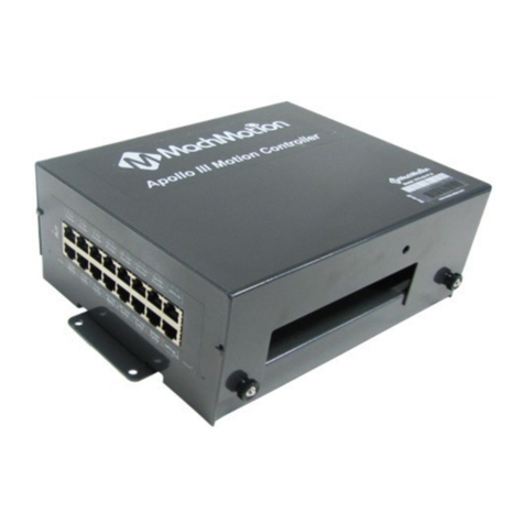
MachMotion Apollo III User manual

Apollo III
MANUAL – MACH3
Specializing in CNC Automation and Motion Control

2 | Page
11/10/14
R0124
This manual covers the setup and configuration of the Apollo III motion controller connected
to the control using Mach3.
Formatting Overview:
•Menus, options, icons, fields, and text boxes on the screen will be bold (e.g. the
Help icon).
•Clickable buttons will be bold and within brackets (e.g. the [OK] button).
•Directory names, commands, and examples of editing program files will appear in
Courier New font
This manual as well as all other MachMotion manuals can be found at www.MachMotion.com
Copyright © 2014, MachMotion
All rights reserved.
Apollo III Using Mach3

Page | 3
Apollo III
R0124
Table of Contents
1PART 1: INTRODUCTION.............................................................................................. 8
1.1 Overview.................................................................................................................................8
1.2 Tool Required..........................................................................................................................8
1.3 Reference Diagram ...............................................................................................................8
1.4 Status LEDs ........................................................................................................................... 10
1.5 Specifications....................................................................................................................... 11
1.6 Drawing ................................................................................................................................ 12
1.7 Hardware Startup .............................................................................................................. 12
1.8 Software Startup ................................................................................................................ 13
2AXIS SETUP ................................................................................................................ 14
2.1 Apollo lll Cover Removal................................................................................................... 14
2.2 Enabling Axes...................................................................................................................... 15
2.3 Axis Calibration .................................................................................................................. 16
2.3.1 Manual Calibration.............................................................................................................. 16
2.3.2 Calibration Wizard .............................................................................................................18
2.4 Backlash Calculation........................................................................................................... 19
2.5 Reversing Direction ............................................................................................................. 20
2.6 Slaving an Axis.................................................................................................................... 20
3SPINDLE SETUP........................................................................................................... 21
3.1 Wiring a Spindle ................................................................................................................ 21
3.1.1 VFD from MachMotion.........................................................................................................21
3.1.2 VFD Other Than from MachMotion...................................................................................22
3.1.3 No VFD...................................................................................................................................22
3.2 Spindle Configuration ........................................................................................................ 23
3.2.1 Spindle Pulley Setup............................................................................................................23
3.3Turning on the Spindle ....................................................................................................... 24
3.4 Reversing Direction ............................................................................................................. 24
4LIMITS AND HOMING SETUP...................................................................................... 25
4.1 Homing Setup ...................................................................................................................... 26
4.2 Soft Limits Setup.................................................................................................................. 27
Apollo III Using Mach3

4 | Page
5INPUT SETUP .............................................................................................................. 28
5.1 Generic Inputs...................................................................................................................... 28
5.2 Wiring Inputs ....................................................................................................................... 29
5.2.1 Standard 24V Inputs ...........................................................................................................29
5.2.2 Sinking Inputs (NPN).............................................................................................................30
5.2.3 Sourcing Inputs (PNP)...........................................................................................................31
5.3 Configuring Inputs............................................................................................................... 31
6OUTPUT SETUP........................................................................................................... 32
6.1 Generic Outputs.................................................................................................................. 32
6.2 Wiring Outputs.................................................................................................................... 33
6.3 Configuring Outputs ........................................................................................................... 34
6.4 Using Outputs ...................................................................................................................... 34
6.5 Mist and Flood Control ...................................................................................................... 35
7ADVANCED OPTIONS ................................................................................................ 35
8PART 2: ADVANCED SETUP ....................................................................................... 40
8.1 Apollo III Network Connection.......................................................................................... 40
8.1.1 Direct Connection..................................................................................................................40
8.1.2 Router Connection................................................................................................................. 42
8.2 Apollo III Software Installation ......................................................................................... 42
8.2.1 Installing Apollo III Plugin and Firmware ......................................................................... 42
8.2.2 Installing VSI Manager........................................................................................................42
8.3 Mach3 Integration .............................................................................................................. 44
8.3.1 Mach3 Startup ......................................................................................................................44
8.4 Apollo III Status Window................................................................................................... 44
8.5 Apollo III Configuration...................................................................................................... 45
9ENABLE CIRCUIT......................................................................................................... 48
9.1 Emergency Stop .................................................................................................................. 48
9.2 Hardware Enable................................................................................................................ 49
9.3 Drive Enable ........................................................................................................................ 51
10 AXES ........................................................................................................................ 53
10.1 Connecting Drives............................................................................................................. 53
10.1.1 Differential Control ...........................................................................................................53
10.1.2 Single-Ended Control........................................................................................................54
10.1.3 Encoder Feedback............................................................................................................. 55
10.2 Configuring Axes.............................................................................................................. 56
10.2.1 Control Parameters ...........................................................................................................57
10.3 Testing Motion................................................................................................................... 58
10.3.1 Test Motion Parameters.................................................................................................... 59
10.4 Backlash Compensation .................................................................................................. 60
10.5 Reversing Direction........................................................................................................... 60
Apollo III Using Mach3

Page | 5
10.6 Slaving an Axis................................................................................................................. 61
11 SPINDLE.................................................................................................................... 62
11.1 Wiring a Spindle.............................................................................................................. 63
11.1.1 VFD....................................................................................................................................... 63
11.1.2 VFD from MachMotion...................................................................................................... 63
11.1.3 No VFD ................................................................................................................................63
11.1.4 Spindle Feedback..............................................................................................................64
11.2 Configuring the Spindle .................................................................................................. 65
11.2.1 Enabling the Spindle......................................................................................................... 65
11.2.2 Spindle Pulley Setup.........................................................................................................67
11.2.3 Analog Calibration............................................................................................................68
11.2.4 RPM Feedback...................................................................................................................68
11.2.5 Servo Spindle Setup .........................................................................................................68
11.2.6 Turning on the Spindle...................................................................................................... 69
12 MPGS ....................................................................................................................... 69
13 INPUTS ..................................................................................................................... 71
13.1 Wiring Inputs..................................................................................................................... 72
13.1.1 Standard 24V Inputs.........................................................................................................72
13.1.2 High Voltage Sourcing Inputs (PNP)............................................................................... 73
13.1.3 Low Voltage Sourcing Inputs (PNP)................................................................................74
13.1.4 Sinking Inputs (NPN)..........................................................................................................74
13.1.5 Isolated Inputs ....................................................................................................................75
13.2 Configuring Inputs ............................................................................................................ 75
14 OUTPUTS.................................................................................................................. 76
14.1 Wiring Outputs................................................................................................................. 77
14.2 Configuring Outputs ........................................................................................................ 78
14.3 Using Outputs.................................................................................................................... 79
15 APPENDICES ............................................................................................................ 80
15.1 Default Factory Settings ................................................................................................. 80
15.1.1 Default Motor Outputs......................................................................................................80
15.1.2 Default Input Signals.........................................................................................................80
15.1.3 Default Output Signals..................................................................................................... 81
15.2 Apollo III Drawing ............................................................................................................ 83
15.3 Apollo III Case Mount Drawing...................................................................................... 85
16 WARRANTY INFORMATION.................................................................................... 87
16.1 Additional Resources ....................................................................................................... 87
Apollo III Using Mach3

6 | Page
**This page intentionally left blank**
Apollo III Using Mach3

Page | 7
Part 1:
INSTALLATION & SETUP
Apollo III Using Mach3

8 | Page
WARNING
Improper installation of this motion controller can cause DEATH, INJURY or serious
PROPERTY DAMAGE. Do not attempt to install this controller until thoroughly
reading and understanding this manual.
1PART 1: INTRODUCTION
1.1 Overview
The Apollo III is MachMotion's Ethernet motion controller. It uses differential or single-ended step and direction to
control up to 6 axes with full encoder feedback (full closed loop). It also has 16 inputs, 8 outputs, excellent
position resolution, two MPG inputs, and spindle encoder feedback
1.2 Tool Required
To use the Apollo III, the following items are necessary:
•24VDC Power Supply
•Emergency Stop Circuit
•Control with Mach3 and Ethernet Port
•Small flat head screw driver
MachMotion CNC controls come with the above items, except the screw driver.
1.3 Reference Diagram
Use the diagram below as a reference throughout the manual.
Apollo III Using Mach3

Page | 9
FIGURE 1 APOLLO III OVERVIEW
WARNING
DO NOT connect 115VAC to any part of the Apollo III motion controller. It could
cause serious damage to the controller.
Apollo III Using Mach3

10 | Page
1.4 Status LEDs
The Apollo III has four status LEDs that show the status of the controller’s processor. The LEDs are located close to
the center of the controller. See the figure below.
Figure 2 Status LEDs
Color
Label
Function
Green
PWR
Power is supplied to Apollo III
Orange
CTRL
Apollo III has an enable signal from control
Red
ERR
Apollo III has an error
Green
CPU
Apollo III CPU is running (should be flashing when power is supplied)
TABLE 1 - APOLLO III STATUS LEDS
Apollo III Using Mach3

Page | 11
1.5 Specifications
Below are the specifications for the Apollo III motion controller.
Item
Specification
Input Power 24VDC
Max Power Consumption 48W
Axes 6
Step and Direction Axis Control
5V Single Ended and Differential
Connection RJ45 Connectors and Terminal Blocks
Max Pulse Speed 1.6 MHz
Encoder Feedback 5V Differential
Connection RJ45 Connectors
Max Frequency
6.25 MHz
Spindle 1
Relay Outputs Clockwise (CW) and Counterclockwise (CCW)
Analog Signal 0-10VDC
Encoder Feedback 5V Differential
Outputs 8
Voltage 7V-48VDC*
Max Current 250mA**
Commons 2
Inputs 16 (Sinking or Sourcing)
Voltage 2.5V-48VDC
Min Current
2mA
Isolated Optional
Enable Circuit 2
Hardware Enable Relay Contacts, 5V Enable, 24V Enable
Drive Enable Relay Contacts
Emergency Stop Circuit Normally Closed Connection
Ethernet Port 10/100 MHz
Dimensions
8.32"(L) X 5.75"(W) X 2"(H)
Optimal Temperature Range 32° to 100°F (0° to 38°C)
TABLE 2 - SPECIFICATIONS FOR THE APOLLO III MOTION CONTROLLER
Apollo III Using Mach3

12 | Page
*Only 24V is provided on the motion controller. Any other voltage must be supplied. **Commons must be supplied externally. If the commons are using the Apollo
III power supply, each output can only source 125mA.
1.6 Drawing
Below is a drawing of the Apollo III.
FIGURE 3 - APOLLO III MOUNTING HOLES
The controller can be mounted on any solid surface that will be protected from dust and dirt. Use a minimum of
3/8 inch standoffs to prevent electrical shorts.
Scale drawing of the Apollo III and mounting case are located in Appendices, pages 83 and 85.
Hardware Startup
To power the Apollo III, you must supply 24VDC to the power connection located at the top right of the board as
shown below. The top orange LED labeled Power will turn on.
FIGURE 4 24V POWER CONNECTOR
Power LED
24V Power
Apollo III Using Mach3

Page | 13
1.7 Software Startup
On the desktop of your control there is a Mach3 shortcut for your machine type. Below are examples of a Mill,
Lathe, and Plasma shortcut.
FIGURE 5 PROFILES
There is also a shortcut for Mach3 Loader. This allows any of the profiles to be loaded from one location. Double
clicking on the Mach3 Loader shortcut opens the following window:
FIGURE 6 LOADER
After double clicking on a profile or opening a profile from Mach3 Loader, a window will come up asking for
agreement with the Mach3 Legal Notice.
FIGURE 7 LEGAL NOTICE
Apollo III Using Mach3

14 | Page
Read the legal notice and click on the check box Please do not ask this again, I will always agree.Then press
[I Agree to all terms of this agreement].
When Mach3 loads, clear the [Reset] button so it is not flashing. [Reset] must be cleared for Mach3 to operate.
2AXIS SETUP
2.1 Apollo lll Cover Removal
All of the drives and external I/O will be wired into the Apollo III. Begin by removing the cover by loosening the
four black knobs on the sides.
FIGURE 8 APOLLO III COVER REMOVED
Note: For more information about the Apollo III see the Apollo III User’s Manual.
Next, plug the drive control and encoder cables into the Apollo III motion controller. The drive control connections
are located on the bottom row of the large RJ45 block. The encoder control connections are located on the top
row of the large RJ45 block. See the picture below.
Apollo III Using Mach3

Page | 15
FIGURE 9 DIFFERENTIAL STEP AND DIRECTION, AND ENCODER FEEDBACK RJ45 CONNECTIONS
2.2 Enabling Axes
After the drives are connected to the Apollo III, open up Mach3, and enable the axes as follows:
Note: This may already be setup depending on your system.
1. On the menu bar, click Config->Ports and Pins.
2. Select the Motor Outputs tab to see the axis enable options as pictured below.
FIGURE 10 AXIS SETUP
3. Enable all the axes that are to be controlled by setting the respective boxes in the Enabled column to
green checks. In the example below, the X, Y, and Z axes are enabled.
Apollo III Using Mach3

16 | Page
FIGURE 11 X, Y, AND Z AXES ENABLED
4. Press [OK] to save any changes and close the window.
The system is now set up for motion.
WARNING
The machine can be crashed very easily. No limit switches have been set up and the
units have not been configured yet.
2.3 Axis Calibration
For the machine to move the correct distance, the axes need to be calibrated. To get the units perfect, they must
be calculated manually from the machine specifications. However, you can get them extremely close if you use
the calibration wizard (see Calibration Wizard on page 18).
2.3.1 Manual Calibration
Complete the following procedure to do the manual calibration:
Note: If the MachMotion plugin is not listed under PlugIn Control, see the Axis Configuration Worksheet to do the
calculations by hand or use the calibration wizard on page 18. The worksheet can be found on the MachMotion
website under software setup documentation.
Go to PlugIn Control->MachMotion Plugin.
1. Select the Calibration tab.
2. Select the drive type of the axis being configured.
3. Enter the max motor RPM.
4. Enter the correct drive ratio.
Apollo III Using Mach3

Page | 17
Drive Ratio Apollo III
Drive Type
1
Teco
32
Mitsubishi
64
Yaskawa
1
Stepper
TABLE 2 – DEFAULT DRIVE RATIO VALUES
FIGURE 12 - MACHMOTION PLUGIN CALIBRATION CALCULATOR
5. Choose the machine configuration for the axis from the following three options.
a. Ball Screw
i. Enter the ball screw pitch
ii. Enter the gearing ratio between the shaft and the motor
Note: If the system has a pulley ratio and a gear box use this equation to get the total gear ratio:
[Gear Box Ratio] x [Pulley Ratio] = [Total Gear Ratio]
Ex: [10:1 Gear Box] x [30 Motor Pulley Teeth/15 Shaft Pulley Teeth] =
[10] x [30/15] = [20 Total Gear Ratio]
b. Rack and Pinion – Pinion Diameter
i. Enter pinion diameter
ii. Enter the gearing ratio between the shaft and the motor
c. Rack and Pinion – Rack Pitch
i. Enter number of teeth on pinion
ii. Enter the rack pitch
iii. Enter the gearing ratio between the shaft and the motor
6. Press the [Calculate] button.
7. Select the axis to calibrate.
8. Press the [Calibrate Axis] button.
Apollo III Using Mach3

18 | Page
9. Repeat starting at step 3 for each additional axis.
10. Restart Mach3 to save the calibration settings.
2.3.2 Calibration Wizard
Complete the following procedure to use the calibration wizard:
1. Run “M9990” from the MDI line.
2. Select the axis to calibrate.
3. Enter in the distance and federate the axis should move.
4. Measure how far the axis moved.
5. Enter in the distance the axis moved.
6. Allow it to update the Steps Per Unit for that axis if the measurement was correct.
7. Repeat this procedure until the axis is within the required accuracy.
If you want to adjust your velocity, select Config on the top menu bar, then Motor Tuning. You should see the
Motor Tuning and Setup window as shown below.
FIGURE 13 MOTOR TUNING AND SETUP
In the column titled Axis Selection, press the button corresponding to the axis you want to set up. The selected
axis’s parameters will be loaded. Now you can adjust your velocity setting as shown below.
Apollo III Using Mach3

Page | 19
FIGURE 14 VELOCITY IN MOTOR TUNING
Press [SAVE AXIS SETTINGS] before clicking on another axis or closing out the Motor Tuning and Setup window.
WARNING
No limits have been set up. DEATH, INJURY or serious PROPERTY DAMAGE can occur if
the system is not operated carefully.
2.4 Backlash Calculation
The Apollo III has backlash compensation. Use the MDI line to enter G-Code to move the axes. To calculate the
machine’s backlash, follow the steps below.
1. Move an axis in one direction farther than the maximum possible backlash.
2. Mount a dial indicator and zero it.
3. Move the axis again in the same direction for a specific distance (it doesn’t matter how far).
4. Move the axis backwards the same distance.
5. Note how far the dial indicator was off from zero to see the axis’s backlash value.
6. On the menu bar go to Config->Config Plugins and press the [CONFIG] button on the HiCON plugin
line.
7. Select the tab corresponding to the desired axis.
8. Enter the backlash distance and speed as described below.
FIGURE 15 BACKLASH COMPENSATION
Apollo III Using Mach3

20 | Page
Backlash (mm, inch) – This field defines the backlash distance in inches or mm. The Apollo III uses this value to
calculate virtual load position.
Backlash Speed % – This field adjusts the maximum acceleration that the backlash counts can be applied. The
Apollo III takes the max acceleration from the motor tuning and multiplies it by this percentage. Valid values are
10-400 (0.1 to 4 times max acceleration). A common value is 20%.
WARNING
Do not leave the backlash speed zero if you enter in a backlash distance. The Apollo
III will not function.
2.5 Reversing Direction
If an axis moves the wrong direction, it can be reversed in the Mach3 software.
1. Navigate to the menu bar and click Config->Homing/Limits.
The following window will come up:
FIGURE 16 REVERSING DIRECTION
2. Under the Reversed column click on the red “X” if the axis needs to be reversed.
3. After making all the changes, press [OK].
The axis will now move the opposite direction than it did before.
2.6 Slaving an Axis
To configure an axis as a slave, follow the steps outlined below.
1. Click Config->Slave Axis on the main menu bar. It will display the Slave Axis Selectionwindow.
Apollo III Using Mach3
Table of contents
Other MachMotion Controllers manuals