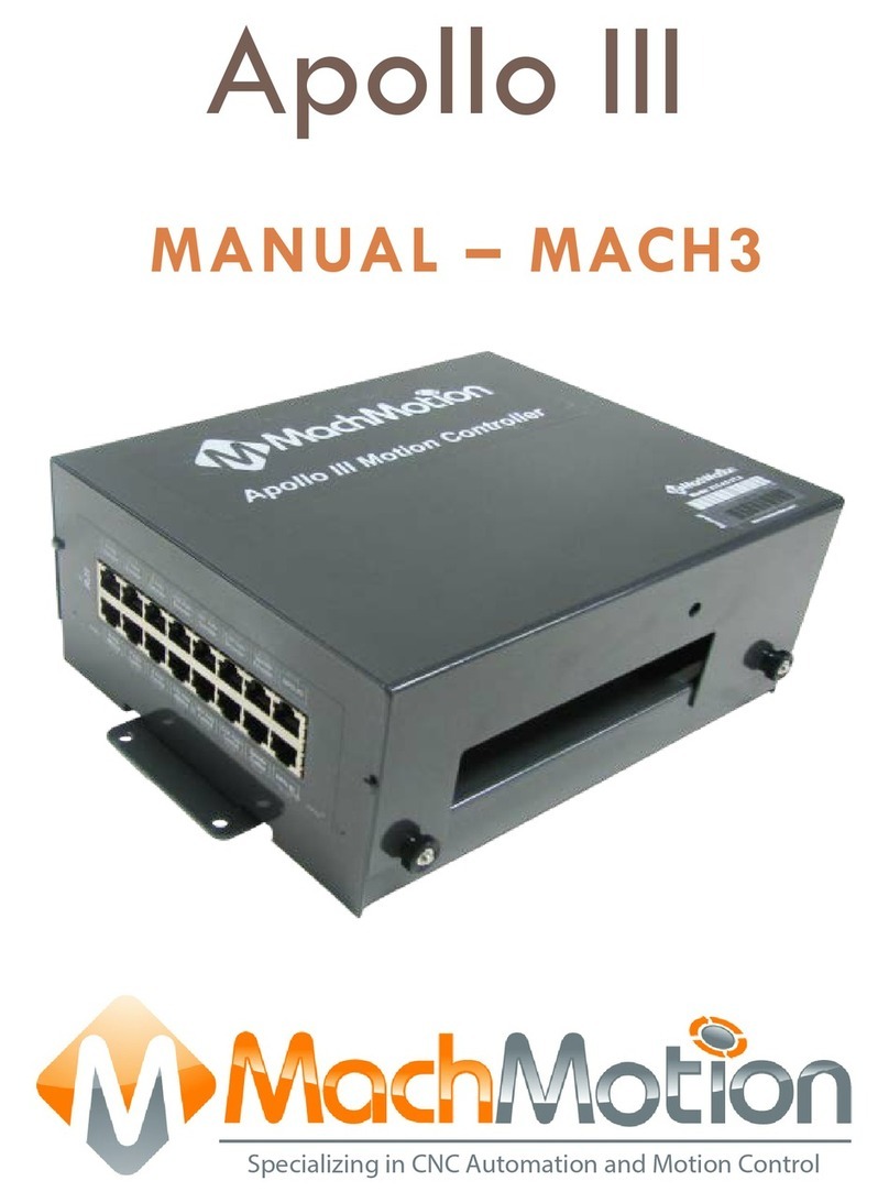
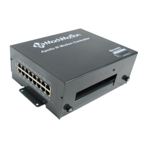
MachMotion Apollo I User manual

The Apollo I Breakout Board provides a flexible, plug-in-play interface for the Mach3 CNC software using standard
computer parallel ports. Its key features include the following:
6 Axis Control
Spindle Control (Clockwise, Counterclockwise, and 0-10VDC Analog)
9 Inputs & 8 Outputs
Emergency Stop Circuit
Hardware and Drive Enable Circuit
1.1 Overview
Use the diagram below as a reference throughout the manual.
Figure 1 Apollo I Overview
The purpose of this manual is to give you all the information you need to use the Apollo I Breakout Board. Written in
simple step by step instructions, this manual can be used by anyone who has a basic understanding of your machine
and basic computer skills.
Apollo I User Manual - Mach3
1. Introduction
WARNING
Do NOT connect 115VAC to any part of the Apollo I Breakout Board. It could cause serious damage to your
board.

1.2 Tools Required
Before operating the Apollo I, you must have the following items:
24VDC Power Supply
Computer with Two Parallel Ports
Mach3 Software
If you purchased a CNC control from MachMotion, you already have all of the above items.
1.3 Specifications
Below are the specifications for the Apollo I Breakout Board.
Item
Specification
Input Power
24VDC
Max Power Consumption
48W
Axes
6
Step and Direction Axis Control
5V Single Ended and Differential
Connection
RJ45 Connectors and Terminal Blocks
Max Pulse Speed
45 kHz
Spindle
1
Relay Outputs
Clockwise (CW) and Counterclockwise (CCW)
Analog Signal
0-10VDC
Outputs
8
Voltage
7V-48VDC*
Max Current
250mA**
Commons
2
Inputs
9 (Sinking or Sourcing)
Voltage
2.5V-48VDC
Min Current
2mA
Isolated
Optional
Enable Circuit
2
Hardware Enable
Relay Contacts, 5V Enable, 24V Enable
Drive Enable
Relay Contacts
Emergency Stop Circuit
Normally Closed Connection
Dimensions
8.32"(L) X 5.75"(W) X 2"(H)
Table 1 Apollo I Specifications
*Only 24V is provided on the breakout board. Any other voltage must be supplied.
**Commons must be supplied externally. If the commons are using the Apollo I power supply, each output can only
source 125mA.

2.1 Mounting
The Apollo I has four 0.16 inch mounting holes as shown below.
Figure 2 Apollo I Mounting Holes
You can mount the breakout board on any solid surface that will be protected from dust and dirt. Make sure to use 3/8
to 1/2 inch standoffs so the bottom of the board will not short out. Place the Apollo I as close to the control as possible.
If the parallel port cables are longer than 12” then you may have issues with electrical noise.
2.2 Supply Power
To turn on the Apollo I you must supply 24VDC. The power connection is located at the top right of the board as shown
below.
Figure 3 24V Power Connector
When 24VDC is supplied, the top orange LED labeled Power will turn on. Near the middle of the board another power
LED should turn on as shown below.
2. Installation

Figure 4 Second Power LED
2.3 Configuring Jumpers
On the Apollo I there are four jumpers that must be set up for it to function properly. As shown below, place all of the
jumpers on the top two pins.
Figure 5 Jumper Configuration
The only jumper you that you should ever use is the CP jumper. It overrides the enable circuit and should only be used
for testing purposes. When the CP jumper is connected to the bottom two pins, the green and blue enable LEDs should
turn on (See Hardware Enable and Drive Enable Sections). Otherwise, the Apollo I is not working correctly.
3.1 Setting up Your Parallel Ports
To connect to the Apollo I, you must have two parallel ports on your computer. Port 1 is on the left and port 2 is on the
right as shown below. Connect them both to the parallel ports on your computer.
3. Apollo I Overview

Figure 6 Parallel Port Connections
Now you need to find your port addresses for ports 1 and 2. Follow the procedure below.
1. Click on Window’s Start button, right click on Computer (or My Computer for Windows XP), and select
Properties.
2. Near the top select the Device Manager. (For Windows XP click on the Hardware tab first.)
3. Expand the Ports (COM & LPT) to see all the parallel ports on your control. For all MachMotion controls PCI
ECP Parallel Ports (LPT2) and PCI ECP Parallel Ports (LPT3) are used for the Apollo I.
Figure 7 Parallel Ports
1. Double click on one of the ports and then select the Resource tab. The first number in the first line of the
range is your port address.

Figure 8 Parallel Port Address
For example, in the figure above, the port address is 0378. Repeat step 4 for the second parallel port.
Now you are ready to load the addresses you found into Mach3. After opening up Mach3, select Config, then Ports
and Pins. Enter in your addresses under Port #1 and Port #2. Delete everything in the address but the “0x”. Then
add your addresses to the end of “0x”. In the example above the port address should be 0x378.
Figure 9 Mach3 Parallel Port Addresses
Press Apply and then OK.
If you used a default XML from MachMotion’s website, your parallel ports should now be set up. Press the Reset button
in Mach3 if it is flashing. The enable LED shown in Figure 14 should be on. Otherwise swap your parallel ports on the
control.
The Apollo I has a hardware and drive enable circuit which turns on when Mach3 turns on the Charge Pump signal.
However, before anything on the Apollo I will work, you must connect the two Emergency Stop terminals. Use the table
below as a quick reference for the different signals.
Signal / LED
Mach3 Name
Port #
Pin #
Input/Output
Enable
Charge Pump
2
17
Output
E-Stop
Estop
2
15
Input
4. Setting up Your Enable Circuit

Table 1 Enable Circuits
Note: If you are using a MachMotion XML or if you purchased a control from MachMotion, both the E-Stop and the
Enable circuits will be set up inside the software.
Emergency Stop
The emergency stop connector is located right below the power connector on the Apollo I. When the emergency stop
terminals are connected together, the red E-Stop LED turns on and the breakout board can then enable.
Figure 10 Emergency Stop Connection
Note: Nothing will work on the Apollo I Breakout Board unless the Emergency Stop terminals are connected together!
Emergency stop input is set up inside Mach3 by setting the EStop signal to port 2 pin 15. Set the Active Low column
to a red X. If it is setup correctly, Mach3 will reset any time the emergency stop terminals are disconnected.
Figure 11 Mach3 EStop Setup
Note: For more information see Configuring Your Inputs section.
4.1 Hardware Enable
WARNING
Do NOT connect 115VAC to any part of the Apollo I Breakout Board. It could cause serious damage to your
board.

The hardware enable is the main enable circuit. It enables all the components on the Apollo I, turns on the 5V enable
(5EN) and the 24V enable signals (24EN), and activates the hardware enable relay (HEN). When the hardware enable
is set up correctly, it will only activate when there are no emergency conditions. Tripping the emergency circuit or a
limit switch will disable the hardware enable. Remember that the emergency stop terminals must be connected for
anything to enable.
The 5V and 24V enable signals can be used for any low current applications. The hardware enable relay can be used
for higher current applications if you supply the voltage source. The signals are labeled 5EN, 24EN, and HEN on the
Apollo I terminal block TB2 as shown below.
Figure 12 Hardware Enable Signals
View the diagram below for an example of the hardware enable relay.
Figure 13 Hardware Enable Relay Example
The green LEDs (labeled Enable) turn on as soon as the breakout board detects the enable signal from Mach3. The
LEDs do not mean that the hardware enable circuit is activated. The hardware enable circuit is only activated when the
red (E-Stop) LED is on.

Figure 14 Hardware Enable LEDs
Hardware enable is set up inside Mach3 by setting the Charge Pump signal to port 2 pin 17 as shown below. Set the
Active Low column to a red X.
Figure 15 Mach3 Charge Pump Setup
Note: For more information see Configuring Your Outputs section.
Note: The Charge Pump also turns on the Drive Enable.
4.2 Drive Enable
Drive enable is used to enable all your drives. When activated, the drive enable relay connects the external enable
(EXT) to the servo enable (SOV) terminals on TB2. The signal SOV runs to each axis control mod jack (See Table 2
Axis Control Mod Jack Pinouts). You can jumper EXT to 5V, 24V, GND, or any other DC voltage for different enable
signals depending on what your servo drives require. Again, remember that the emergency stop terminals must be
connected for anything to enable.

Figure 16 Drive Enable Signals
The Mitsubishi, Yaskawa, and TECO servo drives from MachMotion are all enabled with a ground signal. Therefore EXT
and GND are connected together as shown below.
Figure 17 Drive Enable Example
The blue LED (labeled Drive Enable) on the top middle of the breakout board turns on as soon as the drive enable
signal from Mach3 is detected. The blue LED does not mean that the drive enable relay is activated. The drive enable
relay is only activated when the red (E-Stop), green (Enable), and blue (Drive Enable) LEDs are on.
Figure 18 Drive Enable LED
If you need to use the drive enable signal without using the axis control cables, just connect your signal directly to SOV.
Drive enable uses the same output as the hardware enable. See Figure 15 for the Charge Pump setup.
Now all the LEDs on the Apollo I (besides the inputs and outputs) should be on. If not, go back and make sure that you
set up everything correctly. If all the LEDs are on, you are ready to begin setting up your axes.
To set up your axes you must connect your drives and set up the Mach3 software.
5.1 Connecting Your Drives
The Apollo I Breakout Board uses step and direction to control your axes. You can use differential or single-ended
outputs. For differential outputs you have two signals for step (step + and step -) and two signals for direction
(direction + and direction -). For single-ended you only have one signal for both step and direction. All MachMotion
5. Setting up Your Axes

products use differential outputs.
5.1.1 Differential Control
For most systems you will use differential step and direction. The step and direction outputs are located on the bottom
row of RJ1, the large mod jack block. See the diagram below.
Figure 19 Differential Step and Direction Mod Jacks
The pinout for the mod jacks is shown below.
Function
Reserved
Drive Error
Direction +
Drive
Enable
(SOV)
GND
Direction -
Step +
Step -
RJ45 Pins
1
2
3
4
5
6
7
8
Colors
White &
Orange
Orange
White &
Green
Blue
White & Blue
Green
White &
Brown
Brown
Table 2 Axis Control Mod Jack Pinouts
For any drive from MachMotion, you can plug it directly into the axis control mod jacks.
Note: For more information on the Drive Enable signal, see Drive Enable section.
5.1.2 Single-Ended Control
For single-ended control you can use the terminals on TB1 (the large green terminal block). The top row is for the
direction signals and the middle row is for the step signals. The first letter on each terminal is the axis name and the
second letter is the function (D for direction and S for step). See the picture below.
Table 3 Singled-Ended Step and Direction Terminals
5.2 Enabling Your Axes
After your drives are connected to the Apollo I, open up Mach3 and enable your axes in the following way:

1. On the menu bar, click Config and then Ports and Pins. A window called Engine Configuration… Ports and
Pins will pop up. Select the Motor Outputs tab and you will see the axis setup as pictured below.
Figure 20 Axis Setup
1. Click on the red “X” to enable an axis. If there is a green check mark next to the axis, then the axis is enabled
already. The port and pin numbers must be set up as shown below for anything to work.
Figure 21 X, Y, and Z Axes Enabled
1. Press Apply and then OK. Your axes should now be enabled.
Note: The Dir LowActive and Step Low Ac… columns are not used for the Apollo I Breakout Board.
Now you should be able to jog your axes!
WARNING
Your machine has not be calibrated so it could jog at extremely high speeds and move erroneous distances.
Also, no limits have been set up so you could cause DEATH, INJURY or serious PROPERTY DAMAGE if you are not
careful.

5.3 Calibrating Your Axes
Now you must calibrate your machine. To get your units perfect, you must calculate them manually from your machine
specifications. However, you can get them pretty accurate if you use the calibration wizard (see Calibration Wizard
section).
5.3.1 Manual Calibration
You need to calculate how many steps there are per inch and the maximum velocity of your system. If you purchased
motors from MachMotion, use the table below as a reference.
Motor Type
Encoder Counts
TECO
10,000
Mitsubishi
131,072
Steppers (10 micro-step)
2000
Table 4 Motor Encoder Counts
Calculate the steps per inch and velocity using the steps outlined below.
1. Calculate your gear reduction using the number of teeth on your pulleys and your gearbox ratio. If your motor
is directly driving your axis, then your gear reduction is 1. Otherwise use the formula below.
Gear Reduction = Screw Teeth / Motor Teeth * Gearbox Ratio
1. Now calculate the distance one motor turn will move your axis by taking the ball screw pitch and dividing it by
your gear reduction.
Distance of One Motor Turn = Ball Screw Pitch / Gear Reduction
1. Next calculate the number of steps per inch. Find the number of encoder counts for your drive (which can be
found on the motor specification sheet or in Table 4) and divide it by the distance of one motor turn. This
gives you what Mach3 calls your “Steps per.”
Steps per = Encoder Counts / Distance of One Motor Turn
1. Finally you can calculate your velocity by multiplying your motor’s RPM by the distance of one motor turn.
This gives you your velocity in inches or millimeters per minute.
Velocity = RPM * Distance of One Motor Turn
For example, if you are setting up a 3000 RPM TECO motor with a ball screw pitch of 5 TPI (0.2” pitch) and ball screw
pulley with 36 teeth and a motor pulley with 18 teeth, calculate it as follows.
Begin by calculating your gear reduction. Take the number of teeth on your screw and divide it by the number of teeth
on your motor. In this example the axis has a gear reduction of 2 (36/18).
Now calculate the distance one motor turn will move your axis by taking the ball screw pitch and dividing it by your
gear reduction. In this example one motor turn will move the axis 0.1 inches (0.2”/2).
Next calculate the number of encoder counts per inch (steps per). Find the number of encoder counts for your drive
and divide it by the distance of one motor turn. In this example the steps per inch is 100,000 (10,000/0.1).
Finally, you can calculate your velocity by multiplying your motor’s RPM by the distance of one motor turn. The
velocity in this example is 300 units per minute (0.1*3000).
Now you are ready to enter these values into the Mach3 software. Select Config on the top menu bar, then Motor
Tuning. You should see the Motor Tuning and Setup window as shown below.

Figure 22 Motor Tuning and Setup
On the right column titled Axis Selection, press the button corresponding to the axis you want to set up. The selected
axis’s parameters will be loaded. Now enter in your new value for Steps per as shown below.
Figure 23 Steps per in Motor Tuning
Next enter your velocity as shown below.
Figure 24 Velocity in Motor Tuning
Press SAVE AXIS SETTINGS before clicking on another axis or closing out the Motor Tuning and Setup window.
5.3.2 Calibration Wizard
The calibration wizard is located in the Diagns screen under the Mach Settings tab. Click on the button Set Steps
Per to begin the wizard. If you do not have the Ultimate screen, then you must go to the Settings tab and click on the
Set Steps per Unit button (right above the Reset button).

You will be asked to select an axis and then to enter how far you want the axis to move. After the machine moves, you
will need to measure how far it moved and enter it into the wizard. Repeat the wizard for each axis on your machine.
If you want to adjust your velocity, select Config on the top menu bar, then Motor Tuning. You should see the Motor
Tuning and Setup window as shown below.
Figure 25 Motor Tuning and Setup
On the right column titled Axis Selection, press the button corresponding to the axis you want to set up. The selected
axis’s parameters will be loaded. Now you can adjust your velocity setting as shown below.
Figure 26 Velocity in Motor Tuning
Press SAVE AXIS SETTINGS before clicking on another axis or closing out the Motor Tuning and Setup window.
5.4 Calculating Backlash
The Apollo I has backlash compensation. Use the MDI line to enter g-code to move your axes. To calculate your
machine’s backlash, follow the steps below.
1. Move the axis in one direction farther than the maximum possible backlash.
2. Mount your dial indicator and zero it.
3. Move the axis again in the same direction for a specific distance (it doesn’t matter how far).
4. Move the axis backwards the same distance.
5. Calculate how far the dial indicator was off from zero. This is your backlash value.
After measuring your backlash, load this value into Mach3. Your backlash value must be in inches or millimeters,
depending on what units you are using. Click on Config and then select Backlash. The following window will come up.
WARNING
No limits have been set up. You could cause DEATH, INJURY or serious PROPERTY DAMAGE if you are not careful.

Figure 27 Backlash
Make sure to check the box Backlash Enabled and set the Backlash Speed to 100 as shown above.
You can also change the speed that the backlash is applied. Click on Config then select General Config. The value
Shuttle Accel in seconds is how fast your backlash will be applied.
Figure 28 Shuttle Accel
Below is a table of common values.
Drive Type
Seconds
Steppers
1 to 0.1
Servos
0.01 to 0.0001
Table 5 Backlash Time
5.5 Reversing Direction
If an axis moves the wrong direction, you can reverse the direction in the Mach3 software.
1. Navigate to the menu bar and click Config -> Homing/Limits.

Figure 29 Homing & Limits
You will see the following window come up:
Figure 30 Reversing Direction
1. Under the Reversed column click on the red “X” if the axis needs to be reversed.
2. After making all your changes, press OK.
Your axis will now move the opposite direction than it did before.
5.6 Slaving an Axis
To configure an axis as a slave, follow the steps outlined below.
1. Click Config->Slave Axis on the main menu bar. It will display the Slave Axis Selection window.
Figure 31 Slave Axis Selection Window
1. Select the axis you want to slave. Under X, Y, and Z you can slave either A, B, or C. For example, the
configuration below is used to slave the A axis to the Y axis.

Figure 32 A Axis Slaved to Y
1. Press OK and then restart Mach3.
When Mach3 comes back up, your axis should be slaved correctly.
The Apollo I spindle control consists of a 0-10V analog signal for spindle speed and two relays (CW and CCW) for
spindle direction. Below the spindle terminals on TB2 there are two LEDs for spindle forward (FWD) and reverse (REV).
If these LEDs turn on correctly, then your spindle is set up.
Figure 33 Spindle LEDs
6.1 Wiring up Your Spindle
6.1.1 Spindle Control
Your spindle can be connected into RJ1 or directly into the terminals on TB2 (see Figure 1). On RJ1 the spindle control
connector is on the bottom row as shown below.
Figure 34 Spindle Control RJ45 Mod Jack
The pinout for the spindle control mod jack is shown below.
Function
Analog 0-
10VDC
CW Relay
CW Relay
Drive
Enable
GND
N/C
CCW Relay
CCW Relay
RJ45 Pins
1
2
3
4
5
6
7
8
White &
White &
White &
6. Setting up Your Spindle

Colors
White &
Orange
Orange
White &
Green
Blue
White & Blue
Green
White &
Brown
Brown
Table 6 Spindle Control RJ45 Mod Jack
Note: For more information on the Drive Enable signal, see Drive Enable section.
If you purchased a VFD from MachMotion, then you can plug it directly into the spindle control mod jack.
You can also connect your spindle into the terminals on TB2 as shown below.
Figure 35 Spindle Control Terminals
The terminals and the RJ45 connector both use the same signals. Use whatever method is easiest.
6.2 Setting up the Spindle
Follow the directions below to enable your spindle inside Mach3.
1. Select Config->Ports and Pins and then click on the Motor Outputs tab. Enable the spindle by clicking on
the red “X”. If there is a green check mark next to the spindle, then it is already enabled. Make sure that the
port and pin numbers are set up as shown.

Figure 36 Spindle Setup
1. Now click on the Output Signals tab. Enable outputs 1 and 2 and set them up to port 2 pin 14 and port 2 pin
16 respectively. Set the Active Low column to a red X. See the figure below.
Figure 37 Spindle Outputs
1. Finally, click on the Spindle Setup tab. Make sure the check box Disable Spindle Relays is unchecked and
that the Clockwise Output # is 1 and the Counterclockwise Output # is 2. Also, select the check box
PWM Control and set the PWM Base Freq. to 100.
Table of contents
Other MachMotion Controllers manuals
Popular Controllers manuals by other brands

WindowMaster
WindowMaster WMX 526 Installation instruction

Harmonic Drive
Harmonic Drive RSF-B mini Series manual

Delta
Delta ASC2204C-H user manual

wattstopper
wattstopper DRD6 v2 installation instructions

Wyrestorm
Wyrestorm Enado Mini ENA-MINI-010 quick start guide

EP Solar
EP Solar Tracer-2210RN instruction manual

System air
System air NOTUS-R Installation, maintenance and operation instructions

HANYOUNG NUX
HANYOUNG NUX TH510 Series Operation manual

Samwontech
Samwontech TEMP2000 Series installation manual

Elmo
Elmo VILLEGGIO NG-TRX Series user manual

WindowMaster
WindowMaster WMI 101 installation instructions

System air
System air RE 1 user guide