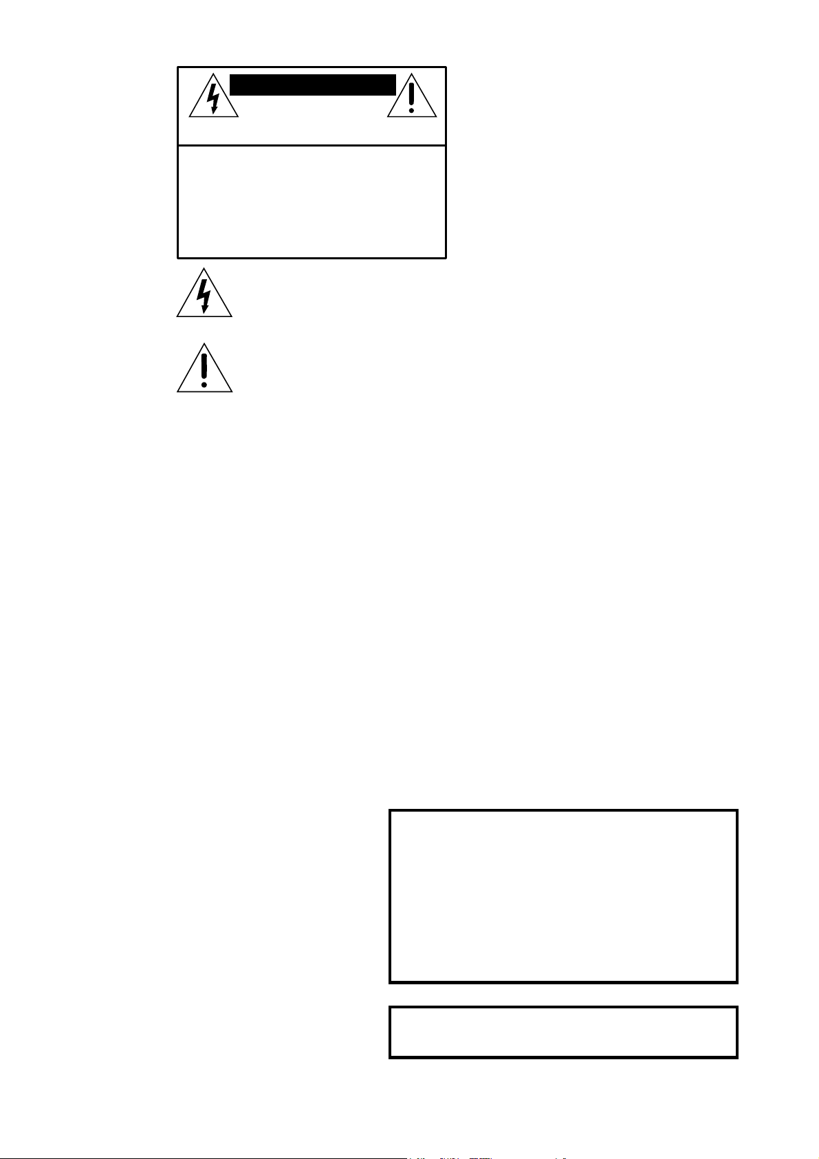
Mackie 1642-VLZ PRO User manual

1642-VLZ PRO
16-CHANNEL
MIC
/
LINE MIXER
OWNER’S MANUAL
1
MUTE
23
MUTEMUTE
4
MUTE
LINE IN
INSERT
X
D
R
M
I
C
P
R
E
MIC
1
BAL
UN-
BAL
LINE IN
INSERT
X
D
R
M
I
C
P
R
E
MIC
2
BAL
UN-
BAL
LINE IN
INSERT
X
D
R
M
I
C
P
R
E
MIC
3
BAL
UN-
BAL
LINE IN
INSERT
X
D
R
M
I
C
P
R
E
MIC
4
BAL
UN-
BAL
LINE IN
INSERT
X
D
R
M
I
C
P
R
E
MIC
5
BAL
UN-
BAL
LINE IN
INSERT
X
D
R
M
I
C
P
R
E
MIC
6
BAL
UN-
BAL
LINE IN
INSERT
X
D
R
M
I
C
P
R
E
MIC
7
BAL
UN-
BAL
LINE IN
INSERT
X
D
R
M
I
C
P
R
E
MIC
8
BAL
UN-
BAL
BAL
UN-
BAL
LINE IN 9
LINE IN 10
X
D
R
M
I
C
P
R
E
MIC
9-10
L
R
13
LEFT
LEFT
RIGHT
LEFT
RIGHT
MONOMONOMONO
14
RIGHT
BAL /
UNBAL
BAL /
UNBAL
15
LEFT
MONO
16
RIGHT
TAPE
IN
TAPE
OUT
BAL
UN-
BAL
LINE IN 11 LINE IN LINE IN
LINE IN 12
X
D
R
M
I
C
P
R
E
MIC
11-12
L
R
PHONES
A
B
LAMP
12 V
0.5A
1642-VLZPRO
16- CHANNEL MIC /LINE MIXER
WITH PREMIUM XDR
TM
MIC PREAMPLIFIERS
U
OO
+20
OO
+20
U
OO
+15
OO
+15
STEREO AUX RETURN
EFFECTS TO MONITORS
TO AUX
SEND 2
TO AUX
SEND 1
1
2
1
2
3
4
C-R / PHNS
ONLY
RETURNS
SOLO
MAIN MIX
TO SUBS
ASSIGN OPTIONS
1
–
2
3
–
4
U
OO
+20
U
OO
+20
U
OO
+10
U
OO
+10
AUX SEND
1
2
PWR
PHAN
SOLO
SOLO
1
2
2
3
TRIM
15
16
U
OO
+15
U
O
U
+15
U
OO
+15
AUX
PRE
U
+20
-20
1
TRIM
13
14
OO
U
+15
AUX
U
+20
-20
2
3
4
1
4
U
+15-15
EQ
U
OO
+15
U
OO
+15
U
OO
+15
PRE
U
+15-15
EQ
12k
HI
12k
HI
OO
+15
O
PAN PAN
HI
MID
3K
LOW
MID
800Hz
80Hz
LOW
LOW
MID
800Hz
80Hz
LOW
LR
U
+15
-15
LR
+15
-15
U
+15
-15
U
+15
-15
U
+15
-15
LOW
MID
800Hz
U
+15
-15
LOW
MID
800Hz
U
+15
-15
U
+15
-15
HI
MID
3K
SUBS 1
–
2
SUBS 3
–
4
MAIN MIX
CR SOURCE
TAPE
OO
MAX
SOLO
RUDE SOLO LIGHT
1
5
2
6
3
7
4
8
LEFT
RIGHT
LEFT
RIGHT
LEFT
RIGHT
LEFT
LEVEL
SET
MODE
(AFL)
LEVEL SET
NORMAL
(PFL)
RIGHT
dB
30
20
10
OO
40
50
5
5
U
60
10
dB
30
20
10
OO
40
50
5
5
U
60
10
TRACK
8
EFX
A
EFX
B
MAIN
MIX
CONTROL ROOM
MAX
OO
MAX
OO
PHONES
U
0 dB= 0 dBu
LEFT RIGHT
OO
+20
TAPE IN
TAPE TO
MAIN MIX
28
10
7
4
2
0
2
4
7
10
20
30
UU
5
MUTE
6
MUTE
7
MUTE
8
MUTE
9-10
MUTE
11 -12
MUTE
13 -14
MUTE
15 -16
MUTE
TRACK
7
TRACK
6
TRACK
5
TRACK
4
TRACK
3
TRACK
2
TRACK
1
REC
1
REC
2
U
TRIM
1
LOW CUT
75 Hz
18dB/OCT
+15dB -45dB
U
U
OO
+15
OO
U
+15
U
OO
+15
AUX
1
PRE
U
+15
-15
FREQ
800
2k200
8k10 0
MID
PAN
LR
U
+15
-15
80Hz
LOW
060
2
3
U
+15-15
EQ
U
OO
+15
4
12k
HI
dB
30
20
10
OO
40
50
5
5
U
60
10
SOLO
1
-
2
3
-
4
L/R
OL
-
20
M
I
C
G
A
I
N
-
1
0
d
B
V
TRIM
2
LOW CUT
75 Hz
18dB/OCT
+15dB -45dB
U
U
OO
+15
OO
U
+15
U
OO
+15
AUX
1
PRE
U
+15
-15
FREQ
800
2k200
8k10 0
MID
PAN
LR
U
+15
-15
80Hz
LOW
060
2
3
U
+15-15
EQ
U
OO
+15
4
12k
HI
dB
30
20
10
OO
40
50
5
5
U
60
10
SOLO
1
-
2
3
-
4
L/R
OL
-
20
M
I
C
G
A
I
N
-
1
0
d
B
V
TRIM
3
LOW CUT
75 Hz
18dB/OCT
+15dB -45dB
U
U
OO
+15
OO
U
+15
U
OO
+15
AUX
1
PRE
U
+15
-15
FREQ
800
2k200
8k10 0
MID
PAN
LR
U
+15
-15
80Hz
LOW
060
2
3
U
+15-15
EQ
U
OO
+15
4
12k
HI
dB
30
20
10
OO
40
50
5
5
U
60
10
SOLO
1
-
2
3
-
4
L/R
OL
-
20
M
I
C
G
A
I
N
-
1
0
d
B
V
TRIM
4
LOW CUT
75 Hz
18dB/OCT
+15dB -45dB
U
U
OO
+15
OO
U
+15
U
OO
+15
AUX
1
PRE
U
+15
-15
FREQ
800
2k200
8k10 0
MID
PAN
LR
U
+15
-15
80Hz
LOW
060
2
3
U
+15-15
EQ
U
OO
+15
4
12k
HI
dB
30
20
10
OO
40
50
5
5
U
60
10
SOLO
1
-
2
3
-
4
L/R
OL
-
20
M
I
C
G
A
I
N
-
1
0
d
B
V
TRIM
5
LOW CUT
75 Hz
18dB/OCT
+15dB -45dB
U
U
OO
+15
OO
U
+15
U
OO
+15
AUX
1
PRE
U
+15
-15
FREQ
800
2k200
8k10 0
MID
PAN
LR
U
+15
-15
80Hz
LOW
060
2
3
U
+15-15
EQ
U
OO
+15
4
12k
HI
dB
30
20
10
OO
40
50
5
5
U
60
10
SOLO
1
-
2
3
-
4
L/R
OL
-
20
M
I
C
G
A
I
N
-
1
0
d
B
V
TRIM
6
LOW CUT
75 Hz
18dB/OCT
+15dB -45dB
U
U
OO
+15
OO
U
+15
U
OO
+15
AUX
1
PRE
U
+15
-15
FREQ
800
2k200
8k10 0
MID
PAN
LR
U
+15
-15
80Hz
LOW
060
2
3
U
+15-15
EQ
U
OO
+15
4
12k
HI
dB
30
20
10
OO
40
50
5
5
U
60
10
SOLO
1
-
2
3
-
4
L/R
OL
-
20
M
I
C
G
A
I
N
-
1
0
d
B
V
TRIM
7
LOW CUT
75 Hz
18dB/OCT
+15dB -45dB
U
U
OO
+15
OO
U
+15
U
OO
+15
AUX
1
PRE
U
+15
-15
FREQ
800
2k200
8k10 0
MID
PAN
LR
U
+15
-15
80Hz
LOW
060
2
3
U
+15-15
EQ
U
OO
+15
4
12k
HI
dB
30
20
10
OO
40
50
5
5
U
60
10
SOLO
1
-
2
3
-
4
L/R
OL
-
20
M
I
C
G
A
I
N
-
1
0
d
B
V
TRIM
8
LOW CUT
75 Hz
18dB/OCT
+15dB -45dB
U
U
OO
+15
OO
U
+15
U
OO
+15
AUX
1
PRE
U
+15
-15
FREQ
800
2k200
8k10 0
MID
PAN
LR
U
+15
-15
80Hz
LOW
060
2
3
U
+15-15
EQ
U
OO
+15
4
12k
HI
dB
30
20
10
OO
40
50
5
5
U
60
10
SOLO
1
-
2
3
-
4
L/R
OL
-
20
M
I
C
G
A
I
N
-
1
0
d
B
V
TRIM
9
10
LOW CUT
75 Hz
18dB/OCT
U
OO
+15
OO
U
+15
U
OO
+15
AUX
1
PRE
U
+15
-15
HI
MID
3K
PAN
LR
U
+15
-15
80Hz
LOW
060
2
3
U
+15-15
EQ
U
OO
+15
4
12k
HI
dB
30
20
10
OO
40
50
5
5
U
60
10
SOLO
1
-
2
3
-
4
L/R
OL
-
20
M
I
C
G
A
I
N
TRIM
11
12
LOW CUT
75 Hz
18dB/OCT
U
OO
+15
OO
U
+15
U
OO
+15
AUX
1
PRE
U
+15
-15
HI
MID
3K
PAN
LR
U
+15
-15
80Hz
LOW
060
2
3
U
+15-15
EQ
U
OO
+15
4
12k
HI
dB
30
20
10
OO
40
50
5
5
U
60
10
SOLO
1
-
2
3
-
4
L/R
OL
-
20
M
I
C
G
A
I
N
dB
30
20
10
OO
40
50
5
5
U
60
10
SOLO
1
-
2
3
-
4
L/R
OL
-
20
dB
30
20
10
OO
40
50
5
5
U
60
10
SOLO
1
-
2
3
-
4
L/R
OL
-
20
L
R
MONO
(BAL/UNBAL)
ON ON
POWER PHANTOM
120 VAC 50/60 Hz 40W
1A/250V SLO-BLO
TO REDUCE THE RISK OF
FIRE REPLACE WITH SAME
TYPE FUSE AND RATING
CAUTION:
AUX RETURN
(BAL/UNBAL)
DIRECT OUTS
(BAL/UNBAL)
SUB OUTS
(BAL/UNBAL)
C
-
R OUTS
(BAL/UNBAL)
MAIN
INSERT
TIP OUT TO EFFECTS DEVICE
RING RETURN FROM EFFECTS
STEREO
PLUG
DIRECT OUT WITH NO SIGNAL
INTERRUPTION TO MASTER
DIRECT OUT WITH SIGNAL
INTERRUPTION TO MASTER
FOR USE AS AN EFFECTS LOOP
(TIP= SEND, RING = RETURN)
INSERT ALL THE WAY IN TO
THE "SECOND CLICK" INSERT ONLY INTO THE
"FIRST CLICK"
MONO PLUG MONO PLUG
CONCEIVED, DESIGNED, AND MANUFACTURED BY MACKIE DESIGNS INC •
WOODINVILLE WA • 98072 • USA • MADE IN USA • PATENTS PENDING •
COPYRIGHT ©1998• THE FOLLOWING ARE REGISTERED TRADEMARKS OF
MACKIE DESIGN INC.: "MACKIE", "XDR", AND THE "RUNNING MAN" FIGURE •
11
8
4321 7654321
5
2
6
3
7
4 234
8
L
R
L
R
L
R
L
R
MAIN
(BAL/UNBAL)
AUX SENDS
(BAL/UNBAL)
MAIN OUTS
L
R
L
R
L
R
LEVEL
1642
-
VLZPRO
16- CHANNEL MIC/ LINE MI XER
WITH PREMIUM XDR
TM
MIC PREAMPLIFIERS
XDR
TM
EXTENDED DYNAMIC RANGE MIC PREAMPLIFIERS ARE PROPRIETARY TO MACKIE DESIGNS, INC.
U
OO
+15
SERIAL NUMBER MANUFACTURING DATE
REPLACEWITH THE SAMETYPE FUSEANDRATING.
DISCONNECTSUPPLYCORDBEFORE CHANGING FUSE UTILISEUN FUSIBLEDERECHANGE DE MÊMETYPE.
DEBRANCHERAVANTDEREMPLACER LE FUSIBLE
WARNING:
TOREDUCETHERISK OF FIRE OR ELECTRIC SHOCK,DO NOT
EXPOSETHISEQUIPMENTTO RAIN OR MOISTURE. DO NOTREMOVE COVER.
NOUSERSERVICEABLE PARTS INSIDE. REFER SERVICING TOQUALIFIED PERSONNEL.
AVIS:
RISQUEDECHOC ELECTRIQUE — NE PAS OUVRIR
RISK OF ELECTRIC SHOCK
DO NOT OPEN
CAUTION
(MONO)(MONO)(MONO)(MONO)
MIC
+4

CAUTION AVIS
RISK OF ELECTRIC SHOCK
DO NOT OPEN
RISQUE DE CHOC ELECTRIQUE
NE PAS OUVRIR
CAUTION: TO REDUCE THE RISK OF ELECTRIC SHOCK
DO NOT REMOVE COVER (OR BACK)
NO USER-SERVICEABLE PARTS INSIDE
REFER SERVICING TO QUALIFIED PERSONNEL
ATTENTION: POUR EVITER LES RISQUES DE CHOC
ELECTRIQUE, NE PAS ENLEVER LE COUVERCLE. AUCUN
ENTRETIEN DE PIECES INTERIEURES PAR L'USAGER. CONFIER
L'ENTRETIEN AU PERSONNEL QUALIFIE.
AVIS: POUR EVITER LES RISQUES D'INCENDIE OU
D'ELECTROCUTION, N'EXPOSEZ PAS CET ARTICLE
A LA PLUIE OU A L'HUMIDITE
The lightning flash with arrowhead symbol within an equilateral
triangle is intended to alert the user to the presence of uninsulated
"dangerous voltage" within the product's enclosure, that may be
of sufficient magnitude to constitute a risk of electric shock to persons.
Le symbole éclair avec point de flèche à l'intérieur d'un triangle
équilatéral est utilisé pour alerter l'utilisateur de la présence à
l'intérieur du coffret de "voltage dangereux" non isolé d'ampleur
suffisante pour constituer un risque d'éléctrocution.
The exclamation point within an equilateral triangle is intended to
alert the user of the presence of important operating and maintenance
(servicing) instructions in the literature accompanying the appliance.
Le point d'exclamation à l'intérieur d'un triangle équilatéral est
employé pour alerter les utilisateurs de la présence d'instructions
importantes pour le fonctionnement et l'entretien (service) dans le
livret d'instruction accompagnant l'appareil.
SAFETY INSTRUCTIONS
1. ReadInstructions—Allthesafetyandoperation
instructionsshouldbereadbeforethisMackieproductis
operated.
2. RetainInstructions—Thesafetyandoperating
instructionsshouldbekeptforfuturereference.
3. HeedWarnings—Allwarningsonthis Mackie productand
intheseoperatinginstructionsshouldbefollowed.
4. FollowInstructions—Alloperatingandotherinstructions
shouldbefollowed.
5. WaterandMoisture—ThisMackieproductshouldnotbe
usednearwater–forexample,nearabathtub,washbowl,
kitchensink,laundrytub,inawetbasement,neara
swimmingpool,swamporsalivatingSt.Bernarddog,etc.
6. Heat—ThisMackieproductshouldbesituatedaway
fromheatsourcessuchasradiators,orotherdeviceswhich
produceheat.
7. PowerSources—ThisMackieproductshouldbe
connectedtoapowersupplyonlyofthetypedescribedin
theseoperationinstructionsorasmarkedonthisMackie
product.
10. Damage Requiring Service — This Mackie product
shouldbeservicedonlybyqualifiedservicepersonnelwhen:
A. Thepower-supplycordortheplughasbeen
damaged;or
B. Objectshavefallen,orliquidhasspilledinto
thisMackieproduct;or
C. ThisMackieproducthasbeenexposedtorain;
or
D. ThisMackieproductdoesnotappeartooperate
normallyorexhibitsamarkedchangein
performance;or
E. ThisMackieproducthasbeendropped,orits
chassisdamaged.
11. Servicing — The user should not attempt to service this
Mackieproductbeyondthosemeansdescribedinthis
operatingmanual.Allotherservicingshouldbereferredtothe
MackieServiceDepartment.
12. To prevent electric shock, do not use this polarized plug
withanextensioncord,receptacleorotheroutletunlessthe
bladescanbefullyinsertedtopreventbladeexposure.
Pourpréevenirleschocsélectriquesnepasutilisercettefiche
polariseéavecunprolongateur,unprisedecourantouune
autresortiedecourant,saufsileslamespeuventêtreinsérées
àfondsanslaisseraucunepariieàdécouvert.
13. GroundingorPolarization—Precautionsshouldbe
takensothatthegroundingorpolarizationmeansofthis
Mackieproductisnotdefeated.
14. This apparatus does not exceed the Class A/Class B
(whicheverisapplicable)limitsforradionoiseemissionsfrom
digitalapparatusassetoutintheradiointerference
regulationsoftheCanadianDepartmentofCommunications.
ATTENTION—Leprésentappareilnumériquen’émetpasde
bruitsradioélectriquesdépassantlaslimitesapplicablesaux
appareilsnumériquesdeclassA/declassB(selonlecas)
prescritesdanslerèglementsurlebrouillageradioélectrique
édictéparlesministeredescommunicationsduCanada.
15. Topreventhazardordamage,ensurethatonly
microphone cables and microphones designed to IEC 268-15A
are connected.
Duration Per Day Sound Level dBA, Typical
In Hours Slow Response Example
8 90 Duoinsmallclub
692
4 95 SubwayTrain
397
2 100 Veryloudclassicalmusic
1.5 102
1 105 PatricescreamingatRonaboutdeadlines
0.5 110
0.25orless 115 Loudestpartsatarockconcert
WARNING —Toreduce therisk of fire or electricshock,
donot expose this appliance torain ormoisture.
8. PowerCordProtection—Powersupply
cordsshouldberoutedsothattheyarenot
likelytobewalkeduponorpinchedbyitems
placeduponoragainstthem,paying
particularattentiontocordsatplugs,
conveniencereceptacles,andthepointwhere
theyexitthisMackieproduct.
9. ObjectandLiquidEntry—Careshouldbe
takensothatobjectsdonotfallintoand
liquidsarenotspilledintotheinsideofthis
Mackie product.

3
We realize that you must have a powerful
hankerin’ to try out your new 1642-VLZ
PRO.
Or you might be one of those people who
never readsmanuals. Either way, all we ask
is that you read this page NOW, and the rest
can wait until you’re good and ready. But do
read it — you’ll be glad you did.
Other Nuggets of Wisdom
Foroptimumsonicperformance,thechannel
fadersandthe
MAIN MIX
fader should be set
nearthe“
U
”(unitygain)markings.
Always turn down the
MAIN MIX
fader and
CONTROL ROOM
and
PHONES
knobs before
making connections to your 1642-VLZPRO.
If you shut down your equipment, turn off
youramplifiersfirst.Whenpoweringup,turn
onyouramplifierslast.
Save the shipping box! You may need it
someday, and you don’t want to have to pay for
anotherone.
INSTANT MIXING
Here’s how to get going
rightaway,assumingyouown
amicrophoneandakeyboard:
1. Plugyourmicrophoneinto Channel 1’s
MIC
input.
2. Turn on the 1642-VLZ
PRO.
3. PerformtheLevel-Setting Procedure .
4. Connectcordsfromthe
MAIN OUT
jacks
toyouramplifier.
5. Hookupspeakerstotheampandturniton.
6. Setchannel1’sfadertothe “U”mark.
7. Engage(pushin)Channel1’s
L/R
switch.
8. Setthe
MAIN MIX
faderone-quarterof
thewayup.
9. Singlikeacanary!
10. Plug your keyboard intochannels3and4.
11. Turnchannel3’s
PAN
knobfullyleftand
channel4’s
PAN
knobfullyright.
12. Set thosefaderstothe“U”mark.
13.
PerformtheLevel-Setting Procedure .
14.
Engagethe
L/R
switchonthesechannels.
15. Playlikea madmanandsinglikeacanary!
It’syourfirst mix!
READ THIS PAGE!!!
Please write your serial number here for
future reference (i.e. insurance claims,
tech support, return authorization, etc.):
Part No. 820-200-00 Rev. A 08/99
©1999 Mackie Designs Inc. All Rights Reserved.
Printed in the U.S.A.
LEVEL-SETTING PROCEDURE
Messagetoseasonedpros:doNOTsetlevels
usingtheold“Turnthetrimupuntiltheclip
lightcomeson,thenbackoffahair”trick.Whena
MackieDesignsmixercliplightcomeson,you
reallyareabouttoclip.
Thisprocedurereallyworks—itassures
lownoiseandhighheadroom.Pleasereadon.
It’snotevennecessarytohearwhatyou’redo-
ingtosetoptimallevels.Butifyou’dliketo:Plug
headphonesintothe
PHONES
outputjack,
thensetthe
PHONES
knob about one-quar-
ter of the way up.
Thefollowingstepsmustbeperformedone
channel at a time:
1. Turn the
TRIM
,
AUX
sendandfader
controlsfullydown.
2. Besurethe
1–2
,
3–4
and
L/R
channel
assignmentswitchesarealldisengaged.
3. Setthe
EQ
knobsatthecenterdetents.
4. Connectthesignalsourcetothe
MIC
or
LINE
channelinput.
5. Engage(pushin)thechannel’s
SOLO
switch.
6. Pushinthe
MODE
switchintheoutput
section(
LEVELSET(PFL)
mode)—the
LEVELSET
LEDwilllight.
7. Playsomethingintotheselectedinput,at
real-worldlevels.
8. Adjustthe
TRIM
controlsothatthe
displayonthemeterstaysaround“0.”
(Onlytheleftmeterisactiveinthe
Level-SettingProcedure.)
9. Ifyou’dliketoapplysome
EQ
,doso
nowandreturntothepreviousstep.
10. Disengagethatchannel’s
SOLO
switch.
11. Repeat for each channel.
Purchased at:
Date of purchase:

4
1
MUTE
23
MUTEMUTE
4
MUTE
LINE IN
INSERT
X
D
R
M
I
C
P
R
E
MIC
1
BAL
UN-
BAL
LINE IN
INSERT
X
D
R
M
I
C
P
R
E
MIC
2
BAL
UN-
BAL
LINE IN
INSERT
X
D
R
M
I
C
P
R
E
MIC
3
BAL
UN-
BAL
LINE IN
INSERT
X
D
R
M
I
C
P
R
E
MIC
4
BAL
UN-
BAL
LINE IN
INSERT
X
D
R
M
I
C
P
R
E
MIC
5
BAL
UN-
BAL
LINE IN
INSERT
X
D
R
M
I
C
P
R
E
MIC
6
BAL
UN-
BAL
LINE IN
INSERT
X
D
R
M
I
C
P
R
E
MIC
7
BAL
UN-
BAL
LINE IN
INSERT
X
D
R
M
I
C
P
R
E
MIC
8
BAL
UN-
BAL
BAL
UN-
BAL
LINE IN 9
LINE IN 10
X
D
R
M
I
C
P
R
E
MIC
9-10
L
R
13
LEFT
LEFT
RIGHT
LEFT
RIGHT
MONO
14
RIGHT
BAL/
UNBAL
BAL/
UNBAL
15
LEFT
MONO
16
RIGHT
TAPE
IN
TAPE
OUT
BAL
UN-
BAL
LINE IN 11 LINE IN LINE IN
LINE IN 12
X
D
R
M
I
C
P
R
E
MIC
11-12
L
R
PHONES
A
B
LAMP
12V
0.5A
1642-VLZ PRO
16-CH ANNEL MIC/ LINE MIX ER
WITH PREMIUM XDRTM MIC PREAMPLIFIERS
U
OO
+20
OO
+20
U
OO
+15
OO
+15
STEREO AUX RETURN
EFFECTS TO MONITORS
TO AUX
SEND 2
TO AUX
SEND 1
1
2
1
2
3
4
C-R/ PHNS
ONLY
RETURNS
SOLO
MAIN MIX
TO SUBS
ASSIGN OPTIONS
1
–
2
3
–
4
U
OO
+20
U
OO
+20
U
OO
+10
U
OO
+10
AUX SEND
1
2
PWR
PHAN
SOLO
SOLO
1
2
2
3
TRIM
15
16
U
OO
+15
U
O
U
+15
U
OO
+15
AUX
PRE
U
+20
-20
1
TRIM
13
14
OO
U
+15
AUX
U
+20
-20
2
3
4
1
4
U
+15-15
EQ
U
OO
+15
U
OO
+15
U
OO
+15
PRE
U
+15-15
EQ
12k
HI
12k
HI
OO
+15
O
PAN PAN
HI
MID
3K
LOW
MID
800Hz
80Hz
LOW
LOW
MID
800Hz
80Hz
LOW
LR
U
+15
-15
LR
+15
-
15
U
+15
-
15
U
+15
-
15
U
+15
-
15
LOW
MID
800Hz
U
+15
-
15
LOW
MID
800Hz
U
+15
-
15
EQ
U
+15
-15
HI
MID
3K
SUBS 1
–
2
SUBS 3
–
4
MAIN MIX
SOURCE
TAPE
OO
MAX
SOLO
RUDE SOLO LIGHT
1
5
2
6
3
7
4
8
LEFT
RIGHT
LEFT
RIGHT
LEFT
RIGHT
LEFT
LEVEL
SET
MODE
(AFL)
LEVEL SET
NORMAL
(PFL)
RIGHT
dB
30
20
10
OO
40
50
5
5
U
60
10
dB
30
20
10
OO
40
50
5
5
U
60
10
TRACK
8
EFX
A
EFX
B
MAIN
MIX
CONTROL ROOM
MAX
OO
MAX
OO
PHONES
U
0 dB=0 dBu
LEFT RIGHT
OO
+20
TAPE IN
TAPE TO
MAIN MIX
28
10
7
4
2
0
2
4
7
10
20
30
UU
5
MUTE
6
MUTE
7
MUTE
8
MUTE
9-10
MUTE
11 -1 2
MUTE
13 -14
MUTE
15 -16
MUTE
TRACK
7
TRACK
6
TRACK
5
TRACK
4
TRACK
3
TRACK
2
TRACK
1
U
TRIM
1
LOW CUT
75 Hz
18dB/OCT
+15dB-45dB
U
U
OO
+15
OO
U
+15
U
OO
+15
AUX
1
PRE
U
+15
-
15
FREQ
800
2k200
8k100
HI
MID
3K
PAN
LR
U
+15
-15
80Hz
LOW
060
2
3
U
+15-15
EQ
U
OO
+15
4
12k
HI
dB
30
20
10
OO
40
50
5
5
U
60
10
SOLO
1
-
2
3
-
4
L/R
OL
-
20
M
I
C
G
A
I
N
-
1
0
d
B
V
TRIM
2
LOW CUT
75 Hz
18dB/OCT
+15dB-45dB
U
U
OO
+15
OO
U
+15
U
OO
+15
AUX
1
PRE
U
+15
-
15
FREQ
800
2k200
8k100
HI
MID
3K
PAN
LR
U
+15
-15
80Hz
LOW
060
2
3
U
+15-15
EQ
U
OO
+15
4
12k
HI
dB
30
20
10
OO
40
50
5
5
U
60
10
SOLO
1
-
2
3
-
4
L/R
OL
-
20
M
I
C
G
A
I
N
-
1
0
d
B
V
TRIM
3
LOW CUT
75 Hz
18dB/OCT
+15dB-45dB
U
U
OO
+15
OO
U
+15
U
OO
+15
AUX
1
PRE
U
+15
-
15
FREQ
800
2k200
8k100
HI
MID
3K
PAN
LR
U
+15
-15
80Hz
LOW
060
2
3
U
+15-15
EQ
U
OO
+15
4
12k
HI
dB
30
20
10
OO
40
50
5
5
U
60
10
SOLO
1
-
2
3
-
4
L/R
OL
-
20
M
I
C
G
A
I
N
-
1
0
d
B
V
TRIM
4
LOW CUT
75 Hz
18dB/OCT
+15dB-45dB
U
U
OO
+15
OO
U
+15
U
OO
+15
AUX
1
PRE
U
+15
-
15
FREQ
800
2k200
8k100
HI
MID
3K
PAN
LR
U
+15
-15
80Hz
LOW
060
2
3
U
+15-15
EQ
U
OO
+15
4
12k
HI
dB
30
20
10
OO
40
50
5
5
U
60
10
SOLO
1
-
2
3
-
4
L/R
OL
-
20
M
I
C
G
A
I
N
-
1
0
d
B
V
TRIM
5
LOW CUT
75 Hz
18dB/OCT
+15dB-45dB
U
U
OO
+15
OO
U
+15
U
OO
+15
AUX
1
PRE
U
+15
-
15
FREQ
800
2k200
8k100
HI
MID
3K
PAN
LR
U
+15
-15
80Hz
LOW
060
2
3
U
+15-15
EQ
U
OO
+15
4
12k
HI
dB
30
20
10
OO
40
50
5
5
U
60
10
SOLO
1
-
2
3
-
4
L/R
OL
-
20
M
I
C
G
A
I
N
-
1
0
d
B
V
TRIM
6
LOW CUT
75 Hz
18dB/OCT
+15dB-45dB
U
U
OO
+15
OO
U
+15
U
OO
+15
AUX
1
PRE
U
+15
-
15
FREQ
800
2k200
8k100
HI
MID
3K
PAN
LR
U
+15
-15
80Hz
LOW
060
2
3
U
+15-15
EQ
U
OO
+15
4
12k
HI
dB
30
20
10
OO
40
50
5
5
U
60
10
SOLO
1
-
2
3
-
4
L/R
OL
-
20
M
I
C
G
A
I
N
-
1
0
d
B
V
TRIM
7
LOW CUT
75 Hz
18dB/OCT
+15dB-45dB
U
U
OO
+15
OO
U
+15
U
OO
+15
AUX
1
PRE
U
+15
-
15
FREQ
800
2k200
8k100
HI
MID
3K
PAN
LR
U
+15
-15
80Hz
LOW
060
2
3
U
+15-15
EQ
U
OO
+15
4
12k
HI
dB
30
20
10
OO
40
50
5
5
U
60
10
SOLO
1
-
2
3
-
4
L/R
OL
-
20
M
I
C
G
A
I
N
-
1
0
d
B
V
TRIM
8
LOW CUT
75 Hz
18dB/OCT
+15dB-45dB
U
U
OO
+15
OO
U
+15
U
OO
+15
AUX
1
PRE
U
+15
-
15
FREQ
800
2k200
8k100
HI
MID
3K
PAN
LR
U
+15
-15
80Hz
LOW
060
2
3
U
+15-15
EQ
U
OO
+15
4
12k
HI
dB
30
20
10
OO
40
50
5
5
U
60
10
SOLO
1
-
2
3
-
4
L/R
OL
-
20
M
I
C
G
A
I
N
-
1
0
d
B
V
TRIM
9
10
LOW CUT
75 Hz
18dB/OCT
+15dB-45dB
U
U
OO
+15
OO
U
+15
U
OO
+15
AUX
1
PRE
U
+15
-
15
HI
MID
3K
PAN
LR
U
+15
-15
80Hz
LOW
060
2
3
U
+15-15
U
OO
+15
4
12k
HI
dB
30
20
10
OO
40
50
5
5
U
60
10
SOLO
1
-
2
3
-
4
L/R
OL
-
20
M
I
C
G
A
I
N
-
1
0
d
B
V
TRIM
11
12
LOW CUT
75 Hz
18dB/OCT
+15dB-45dB
U
U
OO
+15
OO
U
+15
U
OO
+15
AUX
1
PRE
U
+15
-
15
HI
MID
3K
PAN
LR
U
+15
-15
80Hz
LOW
060
2
3
U
+15-15
EQ
U
OO
+15
4
12k
HI
dB
30
20
10
OO
40
50
5
5
U
60
10
SOLO
1
-
2
3
-
4
L/R
OL
-
20
M
I
C
G
A
I
N
-
1
0
d
B
V
dB
30
20
10
OO
40
50
5
5
U
60
10
SOLO
1
-
2
3
-
4
L/R
OL
-
20
dB
30
20
10
OO
40
50
5
5
U
60
10
SOLO
1
-
2
3
-
4
L/R
OL
-
20
Thankyouforchoosing a MackieDesigns
professionalcompactmixer. The1642-VLZPRO
isequippedwithournewprecision-engineered
XDRTM Extended Dynamic Rangepremiummic
preampsfeaturing:
• Full gain range from 0 to 60dB
• +22dBulinesignalhandlingcapability
• 130dBdynamicrange
• Distortionlessthan0.0007%,20Hzto20kHz
• Bullet-proofRFrejectionusingDCpulse
transformercircuitry
• MadeinWoodinville,Washington,USA
Now that you have your 1642-VLZ PRO, find
out how to get the most from it. That’s where
this manual comes in.
HOW TO USE THIS MANUAL
Sincemanyofyoufolkswillwantto hook up
your1642-VLZ
PROimmediately, the first pages
youwillencounterafterthetableof contents are
theeverpopularhookupdiagrams.Theseshow
typicalmixersetupsforRecord/Mixdown,Video,
Stereo PAand a fixed installation.After this sec-
tionisadetailedtouroftheentiremixer.
Everyfeatureofthe1642-VLZ
PROwillbe
described“geographically;”inotherwords,in
orderof whereit isphysicallyplacedonthe
mixer’stopor rearpanel.Thesedescriptionsare
dividedintothe firstthreemanual chapters,just
asyourmixer isorganizedinto threedistinct
zones:
1. PATCHBAY: The zillion jacks along on the
top edge and therear panel
2. CHANNEL STRIP: The channel strips on
the left.
3. OUTPUT SECTION: The output section on
the right.
Whenever a specific 1642-VLZ
PRO compo-
nent is mentioned, it’ll be in all capital letters
sans-serif type. That can help you find refer-
ences to specific controls much faster, without
slowing you down as you read normally. For ex-
ample: The quick brown fader jumped over the
RUDE SOLO LIGHT
.
Throughout these chapters you’ll find illus-
trations, with each feature numbered. If you’re
curious about a feature, simply locate it on the
appropriate illustration, note the number at-
tached to it, and find that number in the nearby
paragraphs or refer to the table of contents.
You’llalsofindcross-referencestothesenum-
beredfeatureswithin aparagraph. Forinstance,if
yousee“Towireyourowncables: ,”simplyfind
that number in the manual and you’ve foundyour
answer. (These are not page numbers.)
You’ll also notice feature numbers just float-
ing in space, like this . These numbers
direct you to relevant information.
This icon marks information
that is critically important or
unique to the 1642-VLZ
PRO.
For your own good, read them
and remember them. They will
be on the final test.
This icon will lead you to in-
depth explanations of features
and practical tips. While not
mandatory, they’ll have some
valuable information.
A PLUG FOR THE CONNECTORS SECTION
TheAppendixgivesdetailsabout connec-
tors:XLRconnectors, balancedconnectors,
unbalancedconnectorsand specialhybrid
connectors.
RACK MOUNTING
Optionalrackearsare available which allow
the1642-VLZPROtobefittedinastandard19"
rack.Thiswilltakeupaheightof12rack
spaces(includingenoughroomtomakethe
connections).ContactyourMackie dealer for
moredetails.
INTRODUCTION
PATCHBAY
CHANNEL STRIPS
OUTPUT
SECTION

5
CONTENTS
OUTPUT SECTION DESCRIPTION ............................ 22
MAIN MIX FADER .......................................... 22
VLZ MIX ARCHITECTURE ................................ 22
SUB FADERS................................................... 22
ASSIGN TO MAIN MIX ................................... 22
TAPE IN (LEVEL)............................................ 22
TAPE TO MAIN MIX........................................ 23
CR SOURCE ................................................... 23
CONTROL ROOM AND PHONES CONTROLS . 23
MODE (NORMAL (AFL)/LEVEL SET (PFL)).........24
LEVEL SET LED ................................................ 24
SOLO (LEVEL) ................................................. 24
RUDE SOLO LIGHT.......................................... 24
METERS ......................................................... 25
AUX DISCUSSION ......................................... 25
AUX SEND (MASTER) ..................................... 25
AUX SEND SOLO ............................................ 26
AUX RETURNS (LEVEL) ................................... 26
EFFECTS TO MONITORS ................................. 26
MAIN MIX TO SUBS (AUX RET 3) ................... 26
1-2/3-4 (AUX RET 3) .................................... 26
C-R/PHNS ONLY (AUX RET 4)........................ 27
RETURNS SOLO.............................................. 27
1642-VLZPRO BLOCK DIAGRAM ............................... 28
GAIN STRUCTURE DIAGRAM ....................................... 29
SPECIFICATIONS .......................................................... 30
SERVICE INFO .............................................................. 31
APPENDIX : Connections .............................................. 32
LEVEL-SETTING PROCEDURE.................................... 3
INSTANT MIXING.................................................... 3
HOOKUP DIAGRAMS .............................................. 6
PATCHBAY DESCRIPTION ......................................... 10
E-Z INTERFACING ......................................... 10
MIC/LINE INPUT FLEXIBILITY..........................10
MIC INPUTS ................................................... 10
PHANTOM POWER DISCUSSION................... 10
LINE INPUTS .................................................. 11
TRIM ............................................................. 11
INSERT........................................................... 11
DIRECT OUT ................................................... 12
RECORDING.................................................. 12
AUX SEND OUTPUTS ...................................... 12
EFFECTS: SERIAL OR PARALLEL? ..................... 13
AUX RETURN INPUTS..................................... 13
SUB OUTS ...................................................... 13
C-R OUTS (CONTROL ROOM OUTPUTS) ...... 14
PHONES OUTPUT ........................................... 14
TAPE OUTPUT ................................................ 14
TAPE INPUT ................................................... 14
MAIN INSERT ................................................. 14
MAIN OUTS ................................................... 14
MONO OUTPUT ............................................. 15
MONO LEVEL ................................................. 15
POWER CONNECTION .................................... 15
FUSE .............................................................. 15
POWER SWITCH ............................................ 15
POWER LED ................................................... 16
PHANTOM SWITCH........................................ 16
PHANTOM LED............................................... 16
BNC LAMP SOCKET ........................................ 16
CHANNEL STRIP DESCRIPTION .............................. 17
“U” LIKE UNITYGAIN.................................. 17
FADER ........................................................... 17
ASSIGN (1-2, 3-4, L/R)................................. 17
SOLO ............................................................. 18
–20 (SOLO) LED ............................................ 18
OL (MUTE) LED .............................................. 18
MUTE............................................................. 19
PAN ............................................................... 19
3-BAND MID-SWEEP EQ................................. 19
4-BAND FIXED FREQUENCY EQ..................... 20
LOW CUT ....................................................... 20
AUX 1, 2, 3, 4 .............................................. 21
PRE ............................................................... 21

6
1642-VLZPRO 8-Track Tracking
HOOKUP DIAGRAMS
EFXA
StereoCompressor
EFXB
CHANNEL INSERTS
CHANNEL INPUTS
AUX SENDS
BAL/UNBAL
TAPE
OUT TAPE
IN
PHONES
OUT SUB OUTS
BAL/UNBAL
C/R OUT
BAL/UNBAL
MAIN
INSERT
AUX RETURNS DIRECT OUT
BAL/UNBAL
MONO
MAIN OUT
BAL/UNBAL
LR L R
Headphones
8TrackRecorder Out
In
FromMics,Keys,
Drummachines
etc.
1
123459-1011-12
2
3
4
StereoProcessor
PoweredMonitors
CassetteRecorder
“tip”
This plug connects to one of the
mixer’s Channel Insert jacks. “ring”
tip ring sleeve
SEND to processor
RETURN from processor
(TRS plug)
This is an insert plug, used to send and receive
on the same TRS connector
(See the diagram below which
shows how to wire Insert plugs)

7
1642-VLZPRO Video setup
CHANNEL INSERTS
CHANNEL INPUTS
AUX SENDS
BAL/UNBAL
TAPE
OUT TAPE
IN
PHONES
OUT SUB OUTS
BAL/UNBAL
C/R OUT
BAL/UNBAL
MAIN
INSERT
AUX RETURNS DIRECT OUT
BAL/UNBAL
MONO
MAIN OUT
BAL/UNBAL
LR L R
Computer
with Audio Card
in
Multi-VCR
Video Switcher
Headphones
Powered
Monitors
CDPlayer
Video
Decks
Video
Master
Keyboard StereoCompressor

8
1642-VLZPRO Stereo P.A.
CHANNEL INSERTS
CHANNEL INPUTS
AUX SENDS
BAL/UNBAL
AUX RETURNS DIRECT OUT
BAL/UNBAL
MONO
MAIN OUT
BAL/UNBAL
LR L R
Turntable
Active
PASpeaker/
Subwoofer
combination
(Pole-mounted
SRM450sand
SRS1500active
Subwoofers
pictured)
Guitar
Guitar
Mic1-5
Processor
Processor
Drum
Machine
MonoEQs,M-1400iAmps,
and(C300)PassiveStageMonitors
Keyboard
Bass
MonoEffects
StereoEffects
Phonopreamp
Additional
stereosource
StereoCompressors
TAPE
OUT TAPE
IN
PHONES
OUT
SUB OUTS
C/R OUT
BAL/UNBAL MAIN
INSERT
Headphones
DigitalMultitrack
Recorder
StereoProcessor
CDPlayer

9
1642-VLZPRO Church Installation
CHANNEL INSERTS
CHANNEL INPUTS
AUX SENDS
BAL/UNBAL
TAPE
OUT TAPE
IN
PHONES
OUT SUB OUTS
BAL/UNBAL C/R OUT
BAL/UNBAL MAIN
INSERT
AUX RETURNS DIRECT OUT
BAL/UNBAL
MONO
MAIN OUT
BAL/UNBAL
LR L R
Headphones
MultitrackRecorder
DirectBox
Mic1-5
Guitar
StereoProcessor
Processor
AssistiveListening
Transmitter
70VoltLineAmp
SRM450sorother
poweredmonitors
HR824sorother
poweredmonitors Monitorsondistributedsystemthroughoutbuilding
DrumMachine
MonoEQs,M-1400iAmps,
and(C300)PassiveStageMonitors
CassetteRecorder
CDPlayer
VCR
Keyboard

10
LINE IN
INSERT
X
D
R
M
I
C
P
R
E
MIC
1
BAL
UN-
BAL
LINE IN
INSERT
X
D
R
M
I
C
P
R
E
MIC
2
BAL
UN-
BAL
LINE IN
INSERT
X
D
R
M
I
C
P
R
E
MIC
3
BAL
UN-
BAL
LINE IN
INSERT
X
D
R
M
I
C
P
R
E
MIC
4
BAL
UN-
BAL
LINE IN
INSERT
X
D
R
M
I
C
P
R
E
MIC
5
BAL
UN-
BAL
LINE IN
INSERT
X
D
R
M
I
C
P
R
E
MIC
6
BAL
UN-
BAL
LINE IN
INSERT
X
D
R
M
I
C
P
R
E
MIC
7
BAL
UN-
BAL
LINE IN
INSERT
X
D
R
M
I
C
P
R
E
MIC
8
BAL
UN-
BAL
BAL
UN-
BAL
LINE IN 9
LINE IN 10
X
D
R
M
I
C
P
R
E
MIC
9-10
L
R
13
LEFT
LEFT
RIGHT
LEFT
RIGHT
MONOMONOMONO
14
RIGHT
BAL /
UNBAL
BAL /
UNBAL
15
LEFT
MONO
16
RIGHT
TAPE
IN
TAPE
OUT
BAL
UN-
BAL
LINE IN 11 LINE IN LINE IN
LINE IN 12
X
D
R
M
I
C
P
R
E
MIC
11-12
L
R
PHONES
A
B
LAMP
12 V
0.5A
1642-VLZPRO
16-CHANNEL MIC / LINE MIXER
WITH PREMIUM XDRTM MIC PREAMPLIFIERS
At the risk of stating the obvious, this is
where you plug everything in: microphones,
line-level instruments and effects, and the ulti-
mate destination for your sound: a tape
recorder, PA system, etc. Many of the features
described in this section are on top of the
mixer, but some are on the rear panel.
E-Z INTERFACING
Concerned about levels,
balancing, impedances, po-
larity, or other interface
goblins? Don’t be. On your
1642-VLZ
PRO, you can patch anything almost
anywhere, with nary a care. Here’s why:
• Every input and output is balanced
(except inserts, phones and RCA jacks).
• Every input and output will also accept
unbalanced lines (except XLR jacks).
• Every input is designed to accept virtually
any output impedance.
• The main left and right mix outputs can
deliver 28dBu into as low as a 600 ohm load.
• All the other outputs can deliver 22dBu
into as low as a 600 ohm load.
• Alltheoutputsareinphasewiththeinputs.
Allweaskis thatyouperformtheLevel-Setting
Procedure everytimeyoupatch inanew
soundsource.Sostop worryingandstartmixing!
MIC AND LINE INPUT FLEXIBILITY
Channels 1-8 are mono channels with
MIC
and
LINE
inputs, featuring our new XDR Ex-
tendedDynamicRangemicpreamp circuitry.
Channels 9-10 and 11-12 are stereo pairs with
left and right
LINE
inputs and a single
MIC
in-
putfeedingeachpair. Channels 13-14 and
15-16 are stereo pairs with
LINE
inputs only.
MIC INPUTS
We use phantom-powered, balanced micro-
phone inputs just like the big studio mega-
consoles, for exactly the same reason: This
kind of circuit is excellent at rejecting hum
PATCHBAY DESCRIPTION
and noise. You can plug in almost any kind of
mic that has a standard XLR-type male mic
connector. Always be sure to perform the
Level-Setting Procedure
. To learn how sig-
nals are routed from these inputs: . If you
wire your own, connect them like this:
2
2
31
1
SHIELD
COLD
HOT
SHIELD
COLD
HOT
3
SHIELD
COLD
HOT
3
2
1
Pin 1 = ground or shield
Pin 2 = positive (+ or hot)
Pin 3 = negative (– or cold)
Professional ribbon, dynamic, and con-
denser mics will all sound excellent through
these inputs. The 1642-VLZ
PRO’s mic inputs
will handle almost any kind of mic level you
can toss at them, without overloading.
A WORD ABOUT PHANTOM POWER
Mostcondensermicsrequirephantom power,
wherethemixersends low-currentDCvoltage to
themic’s electronics through the same wires
that carry audio. The 1642-VLZ
PRO’s phantom
power is globally controlled by the
PHANTOM
switch on the rear panel .
Semipro condenser mics often have batter-
ies to accomplish the same thing. “Phantom”
owes its name to an ability to be “unseen” by
dynamic mics (Shure
®
SM57/SM58, for in-
stance) that don’t need external power and
aren’t affected by it anyway.
Unless you know for
certain it is safe to do so,
never plug single-ended
(unbalanced) micro-
phones, instruments or
electronic devices into the
MIC
input jacks if
the phantom power is on.

11
LINE INPUTS
These
1
/
4
" jacks share circuitry (but not
phantom power) with the mic preamps. You
can use these inputs for virtually any signal
you’ll come across, from instrument levels as
low as –50df to operating levels of –10dBV to
+4dBu, as there is 45dB of gain available via
the
TRIM
knob .
Note that channels 1-8 line inputs are
intially attenuated by 15dB.
Always be sure to perform the
Level-Setting
Procedure
.
To learn how signals are routed from these
inputs: . To connect balanced lines to these
inputs, use a
1
/
4
" tip-ring-sleeve (TRS) plug,
the type found on some stereo headphones:
Tip = positive (+ or hot)
Ring = negative (– or cold)
Sleeve = shield or ground
To connect unbalanced lines to these in-
puts, use a
1
/
4
" mono (TS) phone plug or
standard instrument cable:
Tip = signal (+)
Sleeve = ground
TRIM
These controls are the top row of knobs in
the channel strip section. Every time you plug
something into a
MIC
or
LINE
input jack, you
should perform the
Level-Setting Procedure
, and that procedure is basically “how to use
the
TRIM
knob.”
TRIM
adjusts the input sensitivity of the
MIC
and
LINE
inputs. This allows signals from
the outside world to be adjusted to optimal
internal operating levels.
Through the XLR jack (
MIC
), there will be
0dB of gain with the knob fully down, ramping
to 60dB of gain fully up.
Throughthe
1
/
4
"input(
LINE
),thereis15dB
of attenuation fully down and 45dB of gain fully
up, with a “
U
” (unity gain) mark at 10:00.
This15dBofattenuationcanbeveryhandy
when you are inserting a signal that is very hot,
or you want to add a lot of EQ gain, or both.
Without this “virtual pad,” a scenario like that
might lead to channel clipping.
The
TRIM
controls for
stereo channels 9-10 and
11-12 are only used to ad-
just the Mic inputs. The
line inputs are set to unity
gain.
The
TRIM
controls for channels 13-14 and
15-16 only adjust the line level inputs, as they
have no Mic inputs.
INSERT
These
1
/
4
"jacksarefor connecting serial
effects processors such as compressors, equaliz-
ers, de-essers, or filters . The
INSERT
point is
after the
TRIM
control, but before the channel’s
EQ
,
LOW CUT,
fader and
MUTE
controls. Insert
cables must be wired thusly:
“tip”
This plug connects to one of the
mixer’s Channel Insert jacks. “ring”
tip ring sleeve
SEND to processor
RETURN from processor
(TRS plug)
Tip = send (to effects device input)
Ring = return (from effects device output)
Sleeve = common ground
Even though channels 1–8 already have
DIRECT OUT
jacks ,
INSERT
jacks can also
be used as channel direct outputs; post-
TRIM
,
pre-
LOW CUT
,andpre-
EQ
.Herearethree
ways you can use the
INSERT
jacks:
Direct out with no signal interruption.
Insert only to first “click.”
Channel Insert jack
Channel Insert jack
Channel Insert jack
Direct out with signal interruption.
Insert all the way in to the second “click.”
For use as an effects loop.
(TIP= SEND to effect, RING = RETURN from effect.)
MONO PLUG
MONO PLUG
STEREO
PLUG
1
MUTE
TRIM
1
LOW CUT
75 Hz
18dB/OCT
+15dB - 45dB
U
U
OO
+15
OO
U
+15
U
OO
+15
AUX
1
PRE
U
+15
-
15
FREQ
800
2k200
8k10 0
MID
PAN
LR
U
+15
-15
80Hz
LOW
060
2
3
U
+15-15
EQ
U
OO
+15
4
12k
HI
dB
30
20
10
OO
40
50
5
5
U
60
10
SOLO
1
-
2
3
-
4
L/R
OL
-
20
M
I
C
G
A
I
N
-
1
0
d
B
V
REC
1
SLEEVE
(SHIELD)
TIP (HOT)
TIPSLEEVE
TIP
SLEEVE
SLEEVE
(SHIELD)
TIPSLEEVE
TIP (HOT)
RING (COLD)
RING
TIP
SLEEVERING

12
DIRECT OUT (on rear panel)
Found only on channels 1–8, these
1
/
4
" jacks
deliver the signal from the very end of the
channel path; post-
TRIM
, post-
EQ
, post-
LOW
CUT
,post-faderandpost-
MUTE
.Youcanuse
these for recording, making the 1642-VLZ
PRO
perfect for an 8-track studio.
RECORDING
When recording, you use the first two chan-
nels for your sound sources: vocal mics, drum
mics, keyboard/synth outputs, guitar effects
outputs, that sort of thing. From there, the
channels manipulate the sound, but are not as-
signed to the output section. Instead, they’re
patched from the channel’s
DIRECT OUT
jacks
to any of your 8 multitrack inputs. This allows
recording of two tracks at a time. By recon-
necting the Direct Outs to the different tape
inputs, you can record to all of the 8 tracks.
Once the tracking is completed, the outputs
of the multitrack are then patched to channels
3-12
LINE
inputs on the 1642-VLZ
PRO (multi-
track out 1 to
LINE
input 3, 2 to 4, 3 to 5, etc.).
Aha! That’s why it says “
TRACK 1
” next to chan-
nel 3’s fader, “
TRACK 2
” next to channel 4, and
so forth. These channels (3–12) will be as-
signed to the mixer’s output section, delivering
the signals to their ultimate destination, which
may be your mixdown 2-track, your control
room system, or your headphones.
But let’s not forget that the 1642-VLZ
PRO is
a 4-bus mixer. These buses lead to the
SUB
OUTS
, and are designed to accomplish the
task of getting channels to the multitrack with-
out using the direct outputs.
For example, a channel is assigned to
SUB OUT 1
.
SUB OUT 1
’s output is patched to
multitrack input 1. From there, the multitrack
output goes to the mixer’s channel 3
LINE
input,
as we just discussed. (Hot tip: To feed an 8-
track deck with 4 sub outputs, the 1642-VLZ
PRO has double busing, which simply means
that bus 1 feeds
SUB OUT 1
and
SUB OUT 5
,
bus 2 feeds
SUB OUT 2
and
SUB OUT 6
, bus 3
feeds
SUB OUT 3
and
SUB OUT 7
, and bus 4
feeds
SUB OUT 4
and
SUB OUT 8
. Patch the 8
SUB OUT
s to the inputs of the 8-track deck.
Tracks in record mode will accept the signal,
and tracks in safe mode will ignore the signal.)
The advantages: You can assign any channel
to any track, without repatching. You can as-
sign multiple channels to one track and control
the overall level of that subgroup . You can’t
bounce tracks without this feature.
By returning the outputs of the effects pro-
cessors to 13/14 (EFX A) and 15/16 (EFX B),
you can choose to record or Monitor with ef-
fects.
Perhaps the best recording method is a
combination of both approaches: Use the
SUB
OUTS
to feed multichannel submixes (like a
drum kit) to some of the tracks, and the
DIRECT OUT
jacks to feed single-channel sig-
nals (like bass guitar) to the other tracks.
Thepointisthat youneverlistendirectlyto
thesourcechannels.You listentothemonitor
channels(3–12)andthey’re listeningtothemul-
titrackthatislistening tothesourcechannels.
Themainadvantageis thatyouwon’tbeforced to
constantlyrepatch yourmultitrack—justset it
upandforgetit. You’llalsoknowfor certainthat
thesignalsare indeedgettingtothe multitrack,
sinceyou’re constantlylisteningtoit.
Another method of interfacing a multitrack is
called inline monitoring, and requires a mixing
console dedicated to that, like the Mackie
8•Bus. Each of its channels is actually two chan-
nels: one carrying the mic/line sound source and
the other carrying the multitrack output.
AUX SEND OUTPUTS
These
1
/
4
" jacks usually patch to the inputs
of your parallel effects devices or to the in-
puts of your stage monitor amps. To learn how
signals are routed to these outputs, see the Aux
discussion on page 25.

13
EFFECTS: SERIAL OR PARALLEL?
You’ve heard us carelessly toss around the
terms “serial” and “parallel.” Here’s what we
mean by them:
“Serial” means that the entire signal leaves
the mixer (
INSERT
send), is routed through the
effects device, and returns to the mixer
(
INSERT
return). Examples: compressor, lim-
iter, graphic equalizer. Line-level sources can
also be patched through a serial effects device
before or after the mixer.
“Parallel” means that a portion of the signal
in the mixer is tapped off to the device (
AUX
SEND
), processed, and returned to the mixer
(
AUX RETURN
) to be mixed with the original
“dry” signal. This way, multiple channels can
all make use of the same effects device.
Examples: reverb, digital delay.
AUX RETURN INPUTS
This is where you connect the outputs of your
parallel effects devices (or extra audio sources).
They’ll accept just about any pro or semipro
effects device on the market. See page 26 for
details of the
AUX RETURN
level controls.
Mono: If you have an effects device with a
mono output (onecord), plug that into
L
in-
put of an
AUX RETURN
and leave the right
input unplugged. That way, the signal will be
sent to both sides, magically appearing in the
center as a mono signal.
SUB OUTS
These
1
/
4
" jacks are usually patched to the in-
puts of a multitrack deck, or to secondary
amplifiers in acomplexinstallation. See page
22 for details of the
SUBGROUP FADERS
.
Double Busing
How on earth do you get four buses to
feed eight tracks? Double busing!
• Bus 1 feeds
SUB OUT 1
and
SUB OUT 5
,
which in turn feed tracks 1 and 5
• Bus 2 feeds
SUB OUT 2
and
SUB OUT 6
,
which in turn feed tracks 2 and 6
• Bus 3 feeds
SUB OUT 3
and
SUB OUT 7
,
which in turn feed tracks 3 and 7
• Bus 4 feeds
SUB OUT 4
and
SUB OUT 8
,
which in turn feed tracks 4 and 8
Tracks in record mode will accept the signal,
and tracks in safe mode will ignore the signal.
L
R
MONO
(BAL/UNBAL)
AUX RETURN
(BAL/UNBAL)
DIRECT OUTS
(BAL/UNBAL)
SUB OUTS
(BAL/UNBAL)
C
-
R OUTS
(BAL/UNBAL)
MAIN
INSERT 11
8
4321 7654321
5
2
6
3
7
4 234
8
L
R
L
R
L
R
L
R
MAIN
(BAL/UNBAL)
AUX SENDS
(BAL/UNBAL)
MAIN OUTS
L
R
L
R
L
(MONO)(MONO)(MONO)(MONO)
R
LEVEL
U
OO
+15
MIC
+4
Serial Device (e.g., Compressor)
Parallel Device (e.g., Reverb)

14
L
N
-
L
13
LEFT
LEFT
RIGHT
LEFT
RIGHT
MONOMONO
O
14
RIGHT
BAL /
UNBAL
BAL /
UNBAL
15
LEFT
MONO
16
RIGHT
TAPE
IN
TAPE
OUT
BAL
UN-
BAL
LINE IN 11 LINE IN LINE IN
LINE IN 12
X
D
R
M
I
C
P
R
E
MIC
11-12
L
R
PHONES
A
B
LAMP
12 V
0.5A
C-R OUTS (CONTROL ROOM OUTPUTS)
These
1
/
4
" jacks are usually patched to the
inputs of your control room amplifier or a
headphone distribution amplifier. See page 23
CONTROL ROOM AND PHONES
for de-
tails of the signal routing to these outputs.
PHONES OUTPUTS
The 1642-VLZ
PRO’s stereo
1
/
4
" phones jacks
will drive any standard headphone to very loud
levels. Walkperson-type phones can also be
used with an appropriate adapter. See page 23
CONTROL ROOM AND PHONES
for de-
tails of the signal routing to these outputs. If
you’re wiring your own cable for the
PHONES
output, follow standard conventions:
Tip = left channel
Ring = right channel
Sleeve = common ground
WARNING: When we say
the headphone amp is
loud, we’re not kidding.
It can cause permanent
ear damage. Even inter-
mediate levels may be
painfully loud with some earphones. BE
CAREFUL!
Always turn the
PHONES
knob all the way
down before connecting headphones. Keep it
down until you’ve put the phones on. Then
turn it up slowly. Why? “Engineers who fry
their ears find themselves with short careers.”
TAPE OUTPUT
These unbalanced RCA jacks tap the
MAIN
MIX
outputs to make simultaneous recording
and PA work more convenient. Connect these
to your 2-track recorder’s inputs. See page 22
MAIN MIX FADER
for details of the signal
routing to these outputs.
Mono: If you want to feed a mono signal to
your tape deck or other device, simply use the
1
/
4
"
MONO
output jack . Alternatively, use
an RCA Y-cord to combine the
TAPE OUTPUT
jacks (Radio Shack
®
#274-511, for instance).
Do not attempt this with any other outputs on
the 1642-VLZ
PRO.
TAPE INPUT
These unbalanced RCA jacks are designed
to work with semipro as well as pro recorders.
Connect your 2-track tape recorder’s outputs
here, using standard hi-fi RCA cables. To learn
how signals are routed from these inputs: .
Use these jacks for convenient playback of
your mixes. You’ll be able to review a mix, and
then rewind and try another pass without
repatching or disturbing the mixer levels. You
can also use these jacks with a portable tape
or CD player to feed music to a PA system
between sets .NOTE: Pushing
TAPE TO
MAIN MIX
in the output sec-
tionautomatically
disconnects the
TAPE OUT-
PUT
from the
MAIN OUT
bus.Thispreventscreatingafeedbackloop,
which could create quite a howl in your system
(andyouraudience!).
MAIN INSERT
These
1
/
4
" jacks are for connecting serial
effects such as compressors, equalizers, de-
essers, or filters . The
INSERT
point is after
the mix amps, but before the
MAIN MIX
fader.
Insert cables must be wired thusly:
“tip”
This plug connects to one of the
mixer’s Channel Insert jacks. “ring”
tip ring sleeve
SEND to processor
RETURN from processor
(TRS plug)
Tip = send (to effects device inputs)
Ring = return (from effects device outputs)
Sleeve = common ground (connect shield to
all three sleeves)
MAIN OUTS
Two sets of jacks are provided for the
MAIN
OUTS
,
1
/
4
" TRS jacks and XLR jacks. These are
usually patched to the inputs of your 2-track
mixdown deck (unless you’ve chosen to use
the
TAPE OUTPUT
RCA jacks), or to the house
amplifier during live sound sessions.
In addition, the XLR
MAIN OUTS
have a
switch to match the signal level to the input of
the device you're connecting them to. Push the
SLEEVE
(SHIELD)
TIPSLEEVE
TIP (HOT)
RING (COLD)
RING
TIP
SLEEVERING

15
switch in to connect to semipro –10 dBV de-
vices, and leave the switch out to connect to
professional +4 dBu devices. To learn how sig-
nals are routed to these outputs: . To use
the
1
/
4
" outputs to drive balanced inputs, con-
nect
1
/
4
" TRS (Tip-Ring-Sleeve) phone plugs
like this:
Tip = + (hot)
Ring = – (cold)
Sleeve = ground
To use these outputs to drive unbalanced
inputs, connect
1
/
4
" TS (Tip-Sleeve) phone
plugs like this:
Tip = signal
Sleeve = ground
MONO OUTPUT
It happens to everybody sooner or later:
The forces that govern your world will demand
a monaural output from your painstakingly-
created stereo panorama. The last thing you
want to do is start twirling all your carefully-
placed
PAN
settings to one side. What to do?
Stick a cord in this
1
/
4
" jack, hand the other
end to Mr. Mono, and you’re done. He’s got his
mono mix and you’ve still got your stereo mix.
The
MONO
output is nothing more than a
sum of the left and right
MAIN MIX
.
MONO LEVEL
So, Mr. Mono comes running back, scream-
ing about the mono mix being so loud that his
camcorder is melting. Just reach for this knob
and turn it down a bit. Just the thing for send-
ing mono signals to mic inputs like camcorders,
telephone interface boxes, even answering
machines. With the pot all the way up (fully
clockwise), you’ll have 6 dB of extra gain with
unity gain halfway between the one and two
o’clock positions.
POWER CONNECTION
Just in case you lose the cord provided with
the 1642-VLZ
PRO, its power jack accepts a
standard 3-prong IEC cord like those found on
most professional recorders, musical instru-
ments, and computers. At the other end of our
cord is — get this — a plug! Not a black cube
or, as we’re fond of calling them, a “wall wart.”
We did this for some very good reasons:
The1642-VLZ
PROhassophisticatedpower
requirements that awallwartcannot provide.
Wallwartsare inconvenient,fragile,radiatehuge
humfields,hogextra jacksonyourpowerstrip
andgetinthe way.Ifyoulose awallwart,you’re
introuble,butif youlosethe1642-VLZ
PRO’s
powercord,youcan getanewoneat anyelec-
tronics,music,orcomputer store.Youcaneven
buythemat Radio Shack
®
(part # 278-1257).
Plug the 1642-VLZ
PRO into any standard
grounded (3-pin) AC outlet or into a power
strip of proper voltage.
WARNING: Disconnecting
the plug’s ground pin can
be dangerous. Please
don’t do it.
FUSE
The 1642-VLZ
PRO is fused for your (and
its own) protection. If you suspect a blown
fuse, disconnect the power cord, pull the fuse
drawer out (located just below the cord re-
ceptacle) andreplacethefusewitha 1ASLO
BLO,5x20mm, available at electronics stores or
your dealer (or a 0.5A SLO BLO 5x20mm if
your 1642-VLZ
PRO is a 220V-240V unit).
POWER SWITCH
You can leave this switch on all the time;
the 1642-VLZ
PRO is conservatively designed,
so heat buildup isn’t a problem even in 24-
hour-a-day operation. You may notice that the
1642-VLZ
PRO feels quite warm but there’s
nothing that will burn out or get used up.
SLEEVE
(SHIELD)
TIPSLEEVE
TIP (HOT)
RING (COLD)
RING
TIP
SLEEVERING
SLEEVE
(
SHIELD
)
TIP (HOT)
TIPSLEEVE
TIP
SLEEVE
L
R
MONO
(BAL/UNBAL)
ON ON
POWER PHANTOM
120 VAC 50/60 Hz 40W
1A/250V SLO-BLO
TO REDUCE THE RISK OF
FIRE REPLACE WITH SAME
TYPE FUSE AND RATING
CAUTION:
C
-
R OUTS
(BAL/UNBAL)
MAIN
INSERT
CONCEIVED, DESIGNED, AND MANUFACTURED BY MACKIE DESIGNS INC •
WOODINVILLE WA • 98072 • USA • MADE IN USA • PATENTS PENDING •
COPYRIGHT ©1998• THE FOLLOWING ARE REGISTERED TRADEMARKS OF
MACKIE DESIGN INC.: "MACKIE", "XDR", AND THE "RUNNING MAN" FIGURE •
4321
L
R
L
R
MAIN
(BAL/UNBAL)
AUX SENDS
(BAL/UNBAL)
MAIN OUTS
L
R
LEVEL
U
OO
+15
MIC
+4

16
13
LEFT
LEFT
RIGHT
LEFT
RIGHT
MONO
14
RIGHT
BAL /
UNBAL
BAL /
UNBAL
15
LEFT
MONO
16
RIGHT
TAPE
IN
TAPE
OUT
LINE IN LINE IN PHONES
A
B
LAMP
12 V
0.5A
1642-VLZPRO
16-CHANNEL MIC / LINE MIXER
WITH PREMIUM XDR
TM
MIC PREAMPLIFIERS
ON ON
POWER PHANTOM
120 VAC 50/60 Hz 40W
1A/250V SLO-BLO
TO REDUCE THE RISK OF
FIRE REPLACE WITH SAME
TYPE FUSE AND RATING
CAUTION:
POWER LED
You’ve probably already figured this out, but
if the
POWER
switch is on, this LED (light-
emitting diode), located in the output section,
will light. If the switch is off, well, you get the
idea. If the
POWER
switch is on and the LED
does not glow, one of three things has hap-
pened: Somebody tripped over the power cord
and yanked it from the outlet, your electricity
has been turned off due to nonpayment, or the
fuse has blown .
PHANTOM SWITCH
The
PHANTOM
switch controls the phan-
tom power supply for condenser microphones as
discussed at the start of this section . When
turned on (or off), the phantom power circuitry
takes a few moments for voltage to ramp up (or
down). This is perfectly normal.
PHANTOM LED
Located right next to the
POWER
LED in the
output section, this is just to let you know which
way you have the
PHANTOM
switch set. If your
dynamic mics work and your condensers don’t,
chances are this LED is off, so turn it on.
You’ll notice that when you turn the phan-
tom power off, the LED stays on for a while.
This is a natural phenomenon — the LED is
actually a yellow voltmeter telling you that the
phantom power takes time to ramp itself down
to zero volts. So, if you’ve turned phantom
power off to connect something to the mic in-
puts, wait until the yellow LED stops glowing
and then make your connections safely.
BNC LAMP SOCKET
Located in the top right corner of the out-
put section, this 12V socket will drive any
standard BNC-type lamp (a Littlite
®
#12G or
#12G-HI (high-intensity), for instance).
U
OO
+20
OO
+20
U
OO
+15
OO
+15
STEREO AUX RETURN
EFFECTS TO MONITORS
TO AUX
SEND 2
TO AUX
SEND 1
1
2
1
2
3
4
C-R / PHNS
ONLY
RETURNS
SOLO
MAIN MIX
TO SUBS
ASSIGN OPTIONS
1
–
2
3
–
4
U
OO
+20
U
OO
+20
U
OO
+10
U
OO
+10
AUX SEND
1
2
PWR
PHAN
SOLO
SOLO
1
2
UU

17
CHANNEL STRIP DESCRIPTION
A Clean Fade
Faders are not rocket
science — they operate by
dragging a metal pin (the
wiper)acrossacarbon-based
strip (the track). It is possible for airborne
crud to land on the track. Should that happen,
you may hear scratchy noises or signal drop-
outs as the wiper stumbles over the crud. Do
all you can to keep airborne crud out of your
profession.Useairconditionedroomswhen-
everpossible,avoidsmokingnearthemixer,
keep food and drink away from the mixer, and
for pity’s sake, never put the mixer in your
kitchen!Wealsorecommend“exercising”the
faders — give them a few full-travel excur-
sions once a week or so, and that will help
scare the crud away. We do not recommend
spraycleaners.
ASSIGN (1–2, 3–4, L/R)
Alongside each channel fader are four but-
tons, labeled
SOLO
,
1–2
,
3–4
and
L/R
. The
latter three are collectively referred to as chan-
nel assignment switches.
1
,
3
and
L
are the left
sides of these stereo pairs, and
2
,
4
and
R
are
the right sides. Used in conjunction with the
channel’s
PAN
knob , these switches deter-
mine the destination of a channel’s signal:
With the
PAN
knob set at the center detent,
the left and right sides receive equal signal
levels. To feed only one side or the other, just
turn the
PAN
knob accordingly.
If you’re doing a mixdown to a 2-track, simply
engage the
L/R
switch on each channel that you
want to hear, and they’ll be sent to the
MAIN
MIX
. If you want to create a subgroup of certain
channels, engage either the
1–2
or
3–4
switches
instead of the
L/R
, and they’ll be sent to the ap-
propriate subgroup faders . From there, the
subgroups can be sent back to the
MAIN MIX
, allowing you to use the subgroup faders as a
master control for those channels.
There are eight mono channel strips and
four stereo channel strips. Many of the func-
tions are identical for the mono and stereo
channels. We’ll start at the bottom and work
our way up, pointing out the differences as we
go along.
“U” LIKE UNITY GAIN
Mackie mixers have a “
U
”
symbol on almost every level
control. This “
U
” stands for
“unity gain,” meaning no
change in signal level. Once you have per-
formed the
Level-Setting Procedure
, you
can set every control at “U” and your signals
will travel through the mixer at optimal levels.
What’s more, all the labels on our controls are
measured in decibels (dB), so you’ll know
what you’re doing level-wise if you choose to
change a control’s settings.
You won’t have to check it here and check it
there, as you would with some other mixers. In
fact, some don’t even have any reference to
actual dB levels at all! Ever seen those “0–10”
fader markings? We call these AUMs (Arbitrary
Units of Measurement), and they mean noth-
ing in the real world. You were smart — you
bought a Mackie.
FADER
The fader is almost the last control in a
channel’s signal path. It’s placed after the
EQ
and
MUTE
controls (post-
EQ
/post-
MUTE
and
before the
PAN
control (pre-
PAN
). The “
U
”
mark, about three-quarters of the way up,
indicates unity gain, meaning no increase or
decrease of signal level. All the way up pro-
vides an additional 10 dB, should you need to
boost a section of a song. If you find that the
overall level is too quiet or too loud with a
fader near unity, you’ll want to confirm the
TRIM
setting by performing the
Level-Setting
Procedure
.
1
MUTE
TRIM
1
LOW CUT
75 Hz
18dB/OCT
+15dB - 45dB
U
U
OO
+15
OO
U
+15
U
OO
+15
AUX
1
PRE
U
+15
-
15
FREQ
800
2k200
8k10 0
MID
PAN
LR
U
+15
-15
80Hz
LOW
060
2
3
U
+15-15
EQ
U
OO
+15
4
12k
HI
dB
30
20
10
OO
40
50
5
5
U
60
10
SOLO
1
-
2
3
-
4
L/R
OL
-
20
M
I
C
G
A
I
N
-
1
0
d
B
V
REC
1

18
If you’re printing new tracks or bouncing ex-
isting ones, you’ll also use the
1–2
and
3–4
switches, but not the
L/R
switch. Here, you
don’t want the subgroups sent back into the
MAIN MIX
, but sent out, via the
SUB OUTS
jacks, to your multitrack inputs . However, if
you’re printing tracks via the
DIRECT OUT
jacks , all the channel assignment switches
should be disengaged (up).
The 1642-VLZ
PRO is what we call a “true
4-bus mixer.” Each channel can be assigned or
unassigned to any of the subgroups without af-
fecting the other subgroups or settings within
the channel, and each subgroup has its own
master fader and dedicated output . In
fact, since there are 4 subgroups andthe
MAIN
L/R MIX
, it’s actually a true 6-bus mixer. We
could have named it the 1662-VLZ PRO. Darn!
SOLO
This lovable switch allows you to check
signals through your
PHONES
output or
C-R
OUTS
without having to assign them to the
L/R
,
1-2
or
3-4
mixes. You can solo as many
channels as you like.
SOLO
does not interrupt
any of the other channels, buses or outputs —
that’s called nondestructive solo. Not only that,
via the
MODE
switch , the 1642-VLZ
PRO’s
solo system comes in two flavors:
NORMAL
(AFL)
(sometimes called SIP, or solo-in-place)
and
LEVEL SET (PFL)
(sometimes called PFL,
or pre-fader-listen).
During
NORMAL (AFL)
mode, the soloed
channel’ssignal is sentdirectly tothe
C-R OUTS
,
PHONES
output, and meter display just as it
would sound to the channel’s assignment
switches: post-
EQ
, post-fader and post-
PAN
.
The only difference is that
SOLO
works re-
gardless of the channel’s assignment positions,
and that makes it really handy — you can
check out a channel before you assign it.
NORMAL (AFL)
is the preferred mode during
mixdown: If the channel has some midrange
boost at 4.2kHz, is panned a smidgen to the
left, and its fader is at –5dB, that’s exactly
what you’ll hear if you
SOLO
during
NORMAL
(AFL)
mode. It’s just as if you took the time to
MUTE
all the other channels.
LEVEL SET (PFL)
solo is the key player in the
all-important
Level-Setting Procedure
. It’ll
send the channel’s actual internal levels to the
meters so you’ll know just what’s going on, level-
wise. This procedure should be performed every
time a new sound source is patched into a
channel’s
MIC
or
LINE
input jacks.
LEVEL SET (PFL)
is also the preferred mode
for SR (sound reinforcement, or live sound), to
preview channels before they are let into the
mix. It won’t give you stereo placement, but will
give you signal even if the fader is pulled down.
Remember,
LEVEL SET (PFL)
tapsthechan-
nel signal before the fader. If you have a
channel’s fader set way below “
U
” (unity gain),
SOLO
won’t know that and will send a unity
gain signal to the
C-R OUTS
,
PHONES
output
and meter display. That may result in a startling
level boost at these outputs, depending on the
position of the
SOLO
level knob .
In a nutshell, soloed channels are sent to
the
SOURCE
mix , that ultimately feeds your
C-R OUTS
,
PHONES
output and meter display.
Whenever
SOLO
is engaged, all
SOURCE
se-
lections (
MAIN MIX
,
1–2
,
3–4
and
TAPE
) are
defeated, to allow the soloed channel to do just
that —
SOLO
!
–20 (SOLO) LED
An LED that does two completely different
things! Saves space, but requires some expla-
nation. First, the “
–20
” part: Often referred to
as “signal activity,” this LED will flicker in time
with the signal present in that channel. It’s
handy for confirming that a channel is indeed
active, and may also lend a clue as to what the
signal is. For instance, a kick drum will cause
the LED to pulse in time with the drum, and a
synth pad will cause it glow a bit more steadily.
Now for the “
SOLO
” part. When a channel’s
SOLO
switch is engaged, this LED will glow
steadily, without flickering. It will also be
brighter than it would be as a
–20
indicator. In
conjunction with the
RUDE SOLO LIGHT
,
you can find a rogue
SOLO
switch very quickly.
OL (MUTE) LED
Another LED that does two completely differ-
entthings!First,the“
OL
”part:“
OL
”means
overload, or clip. You don’t want that to happen.
Ever. Clipping can happen to any mixer — it’s
the point where the signal’s voltage exceeds the
supply voltages that power the circuitry. The
1642-VLZ
PRO’s
OL
LED will come on just be-
fore clipping, so if you see it, take immediate
action: Perform the
Level-Setting Procedure
.
If that doesn’t help, check for excessive use of
EQ
boost or
fader
gain. Like the
–20
LED, it will
tend to flicker in time with that channel’s signal.
Now for the “
MUTE
” part. Assuming your
levels are set correctly, the
OL
LED will never
come on as a result of clipping. That’s pretty
1
MUTE
TRIM
1
LOW CUT
75 Hz
18dB/OCT
+15dB - 45dB
U
U
OO
+15
OO
U
+15
U
OO
+15
AUX
1
PRE
U
+15
-
15
FREQ
800
2k200
8k10 0
MID
PAN
LR
U
+15
-15
80Hz
LOW
060
2
3
U
+15-15
EQ
U
OO
+15
4
12k
HI
dB
30
20
10
OO
40
50
5
5
U
60
10
SOLO
1
-
2
3
-
4
L/R
OL
-
20
M
I
C
G
A
I
N
-
1
0
d
B
V
REC
1

19
Stereo Sources
Use channels 9-16 to connect stereo sound
sources. If you must use the mono channel
strips (1-8) for stereo sources, follow this stan-
dard convention: Always plug the left signal
into an “odd” channel (
1
,
3
,
5
, etc.) and the
right signal into the adjacent “even” channel
(
2
,
4
,
6
, etc.). Then pan the odd channel hard
left and the even channel hard right.
CONSTANT LOUDNESS !!!
The 1642-VLZ
PRO’s
PAN
controls employ a design
called “Constant Loudness.”
It has nothing to do with liv-
ing next to a freeway. As you turn the
PAN
knob from left to right (thereby causing the
sound to move from the left to the center to
the right), the sound will appear to remain at
the same volume (or loudness).
If you have a channel panned hard left (or
right) and reading 0 dB, it must dip down
about 4 dB on the left (or right) when panned
center. To do otherwise, like those Brand X
mixers, would make the sound appear much
louder when panned center.
3-BAND MID-SWEEP EQ
The1642-VLZ
PRO mono channels have a 3-
band, mid-sweep equalization:
LOW
shelving at
80Hz,
MID
sweep peaking from 100Hz to 8kHz,
and
HI
shelvingat12kHz.It’sprobablyallthe
EQ you’ll ever need! (Shelving means that the
circuitry boosts or cuts all frequencies past the
specified frequency. For example, the 1642-VLZ
PRO’s
LOW EQ
boosts bass frequencies starting
at 80Hz and continuing down to the lowest note
you never heard. Peaking means that certain
frequencies form a “hill” around the center fre-
quency.)
The
LOW EQ
providesupto15dBboostorcut
at80Hz.Thecircuitisflat(noboostor cut)atthe
centerdetentposition.Thisfrequencyrepresents
thepunchinbassdrums,bassguitar,fatsynth
patches,andsomereallyseriousmalesingers.
20
Hz
100
Hz
1k
Hz
10k
Hz
20k
Hz
–15
–10
–5
0
+5
+10
+15
boring. So, to liven things up, this LED will
glow steadily when that channel’s
MUTE
switch is engaged.
If you need a quick reference to these LEDs,
write this on the back of your hand:
Name Color Flickering Glowing
–20(Solo) green signalispresent channel issoloed
OL(Mute) red channel is clipping channel ismuted
MUTE
Engaging a channel’s
MUTE
switch pro-
vides the same results as turning the fader all
the way down: Any channel assignment to
L/R
,
1-2
or
3-4
will be interrupted. All the
post
AUX
sends will be silenced, as will
the
DIRECT OUT
signals on channels
1
through
8
. And of course, that fun-loving
OL
(
MUTE
)
LED will commence to glow. The
PRE AUX
sends , channel
INSERT
send
and
SOLO
(in
LEVEL SET (PFL)
mode) will
continue to function during
MUTE
.
Depending on the audio content in a chan-
nel, engaging its
MUTE
switch may cause a
slight popping sound. This is not a problem
within the mixer, and it can be avoided: Sim-
ply engage the
LOW CUT
switch on each
channel (unless its low frequency content is
vitally important, such as a kick drum or bass
guitar).
LOW CUT
eliminates subsonic de-
bris, which causes the pop, and its effect is
usually transparent.
PAN
PAN
adjusts the amount of channel signal
sent to the left versus the right outputs. Pan de-
termines the fate of the
L/R
assignment,
subgroups
1–2
and
3–4
, and the
SOLO
(in
NORMAL (AFL)
mode). With the
PAN
knob
hard left, the signal will feed the left
MAIN MIX
,
subgroup
1
, subgroup
3
and left
NORMAL
(AFL)
solo mode (assuming their assignment
switches are engaged). With the knob hard
right, signal feeds the right
MAIN MIX
, sub-
group
2
, subgroup
4
and right
NORMAL (AFL)
solo mode. With the
PAN
knob set somewhere
in-between left and right, the signal will be di-
vided between the left and right buses.
The PAN knob behaves a little differently for
the stereo channel strips. Since there is a left
and right input on these channels, the PAN
knob controls the relative balance between the
left and right sides, just like the balance con-
trol on your stereo system at home.
1
MUTE
TRIM
1
LOW CUT
75 Hz
18dB/OCT
+15dB - 45dB
U
U
OO
+15
OO
U
+15
U
OO
+15
AUX
1
PRE
U
+15
-
15
FREQ
800
2k200
8k10 0
MID
PAN
LR
U
+15
-15
80Hz
LOW
060
2
3
U
+15-15
EQ
U
OO
+15
4
12k
HI
dB
30
20
10
OO
40
50
5
5
U
60
10
SOLO
1
-
2
3
-
4
L/R
OL
-
20
M
I
C
G
A
I
N
-
1
0
d
B
V
REC
1

20
Used in conjunction with the
LOW CUT
switch , you can boost the
LOW EQ
without
injecting a ton of subsonic debris into the mix.
We recommend using the
LOW CUT
feature on
all channels, except low frequency signals, like
kick drums and bass guitars.
The
MID EQ
, or “midrange,” has a fixed
bandwidth of 1.5 octaves. The
MID
knob sets
the amount of boost or cut, up to 15 dB, and is
effectively bypassed at the center detent. The
frequency knob sets the center frequency,
sweepable from 100Hz to 8kHz.
20
Hz
100
Hz
1k
Hz
10k
Hz
20k
Hz
–15
–10
–5
0
+5
+10
+15
20Hz 100Hz 1kHz 10kHz 20kHz
–15
–10
–5
0
+5
+10
+15
Most of the root and lower harmonics that
define a sound are located in the 100Hz–8kHz
frequency range, and you can create drastic
changes with these two knobs. Many engineers
use
MID EQ
to cut midrange frequencies, not
boost them. One popular trick is to set the
MID
fully up, turn the frequency knob until you find
a point where it sounds just terrible, then back
the
MID
down into the cut range, causing
those terrible frequencies to disappear. Sounds
silly, but it works. Sometimes.
The
HI EQ
providesyouupto 15dBboostor
cutat12kHz,and it isalsoflatat thedetent. Use
ittoaddsizzle tocymbals,anoverallsense of
transparency,oranedge tokeyboards,vocals,gui-
tarandbaconfrying. Turnitdowna little to
reducesibilance ortomasktape hiss.
20
Hz
100
Hz
1k
Hz
10k
Hz
20k
Hz
–15
–10
–5
0
+5
+10
+15
With too much
EQ
, you can screw things up
royally. We’ve designed a lot of boost and cut
into each equalizer circuit because we know
everyone will occasionally need that. But if you
max the
EQ
on every channel, you’ll get mix
mush. Equalize subtly and use the left sides of
the knobs (cut), as well as the right (boost). If
you find yourself repeatedly using full boost or
cut, consider altering the sound source, such
as placing a mic differently, trying a different
kind of mic, changing the strings, or gargling.
4-BAND FIXED-FREQUENCY EQ
The stereo channels (9-16) have a 4-band,
fixed-frequency equalization:
LOW
shelving at
80Hz,
LOW MID
peaking at 800Hz,
HI MID
peaking at 3kHz, and
HI
shelving at 12kHz.
Each of these filters provides up to 15 dB of
boost or cut. As with the mono channels, the
circuit is flat (no boost or cut) at the center
detent positions.
LOW CUT
The
LOW CUT
switch (not present on
channels 13-16), often referred to as a high
pass filter (all depends on how you look at it),
cuts bass frequencies below 75Hz at a rate of
18 dB per octave. This ain’t no thrown-in
dime-store filter — an 18 dB per octave curve
requires an elaborate circuit. Nothing but the
best for you.
Werecommend thatyouuse
LOW CUT
onev-
erysoundsourceexcept kickdrum,bassguitar,
bassysynthpatches,or recordingsof earth-
quakes.Theseaside,thereisn’tmuch down there
thatyouwantto hear,andfiltering it outmakes
thelowstuffyou dowantmuchmorecrispand
tasty.Notonlythat,but lowcutcanhelpreduce
thepossibilityoffeedback inlivesituations,andit
helpstoconserveamplifier power.
With
LOW CUT
, you can safely boost
LOW
EQ
. Many times, bass shelving eq can really
benefit voices. Trouble is, adding
LOW EQ
also
boosts the subsonic debris: Stage rumble, mic
handling clunks, wind noise and breath pops.
LOW CUT
removes all that debris so you can
boost the
LOW EQ
without frying your woofer.
Here’s a frequency curve of
LOW EQ
combined
with
LOW CUT
:
20Hz 100Hz 1kHz 10kHz 20kHz
–15
–10
–5
0
+5
+10
+15
1
MUTE
TRIM
1
LOW CUT
75 Hz
18dB/OCT
+15dB - 45dB
U
U
OO
+15
OO
U
+15
U
OO
+15
AUX
1
PRE
U
+15
-
15
FREQ
800
2k200
8k10 0
MID
PAN
LR
U
+15
-15
80Hz
LOW
060
2
3
U
+15-15
EQ
U
OO
+15
4
12k
HI
dB
30
20
10
OO
40
50
5
5
U
60
10
SOLO
1
-
2
3
-
4
L/R
OL
-
20
M
I
C
G
A
I
N
-
1
0
d
B
V
REC
1
Mono Channel
Other manuals for 1642-VLZ PRO
6
Table of contents
Other Mackie Music Mixer manuals

Mackie
Mackie 1402VLZ4 User manual

Mackie
Mackie 1202-VLZ3 User manual

Mackie
Mackie Onyx 1620i Assembly instructions

Mackie
Mackie ONYX 1640I User manual

Mackie
Mackie D8B User manual

Mackie
Mackie D8B Manual

Mackie
Mackie PPM1008 User manual

Mackie
Mackie D8B3.0 User manual

Mackie
Mackie 1642-VLZ PRO Manual

Mackie
Mackie Ultra-34 User manual

Mackie
Mackie DL1608 Dimensions

Mackie
Mackie PPM1012 User manual

Mackie
Mackie ProFXv3+ Series User manual

Mackie
Mackie MicroSeries 1202 User manual

Mackie
Mackie Onyx 2480 User manual

Mackie
Mackie DL1608 User manual

Mackie
Mackie 1604-VLZ3 User manual

Mackie
Mackie 1402VLZ4 User manual

Mackie
Mackie ProDX4 User manual

Mackie
Mackie MCE User manual