Mackie HUI User manual

HUI
Human User Interface
for Digital Audio Workstations
Reference Guide
TM
MONITOR OUTPUTS
MIC 1
MONITOR INPUTS
PHONES
OUT
BAL /
UNBAL
OUT
BAL /
UNBAL
INSERT
TRIM
MOUSE
KEYBOARD
SERIAL PORT
EXPANSION
IN
ON
OFF
THRU
IN THRU
MIDI IN
POWER MIDI OUT
L/MONO
SERIAL NUMBER MANUFACTURINGDATE
RISK OF ELECTRIC SHOCK
DO NOTOPEN
REPLACE WITH THE SAME TYPE FUSE AND RATING.
DISCONNECT SUPPLYCORD BEFORE CHANGING FUSE
UTILISE UN FUSIBLE DE RECHANGE DE MÊME TYPE.
DEBRANCHER AVANTDE REMPLACER LE FUSIBLE
WARNING:
TOREDUCE THE RISK OF FIRE OR ELECTRIC SHOCK, DO NOT
EXPOSETHIS EQUIPMENT TO RAIN OR MOISTURE. DO NOT REMOVE COVER.
NO USER SERVICEABLE PARTS INSIDE. REFER SERVICING TOQUALIFIED PERSONNEL.
CAUTION
AVIS:
RISQUE DE CHOC
É
LECTRIQUE — NE PASOUVRIR
1
2
3
RL
1
2
3
TRIM
REMOTE
TALKBK
TRIGGER
INTERNAL
EXTERNAL
MIC
INPUT
MIC
INPUT
+48V
PHANTOM
+48V
PHANTOM
+48V
PHANTOM
MIC
INPUT
TRIM
R
MIC 2
MIC
TALKBACK
060 dB 60 dB 60 dB0
0
IN
OUT
INSERT
IN
OUT
RS232
RS422
G
A
I
N
G
A
I
N
G
A
I
N
FOOTSWITCH
IN
RELAY
OUT
1 2
1 2
CONCEIVED, DESIGNED, AND MANUFACTURED BY MACKIE DESIGNS INC • WOODINVILLE • WA • 98072 • USA • MADE IN USA • FABRIQUE AU USA • PATENTS PENDING
COPYRIGHT ©1997 • THE FOLLOWING ARE REGISTERED TRADEMARKS OF MACKIE DESIGN INC.: "MACKIE", HUI, AND THE "RUNNING MAN" FIGURE •
120V, 60Hz, .85A
FUSE 1.25A, 250V SLOW
MACKIE DESIGNS THIS DEVICE COMPLIES WITH PART 15 OF THE FCC RULES. OPERATION IS SUBJECT TO THE FOLLOWING TWO CONDITIONS: 1) THIS DEV ICE MAYNOT C AUSE HARMFUL INTERFERENCE AND 2) THIS DEVICE MUST ACCEPT ANY INTERFERENCE RECEIV ED THATMAY CAUSE UNDESIRED OPERATION
REC/RDY
INSERT
REC/RDY
INSERT
REC/RDY
INSERT
REC/RDY
INSERT
REC/RDY
INSERT
REC/RDY
INSERT
REC/RDY
INSERT
REC/RDY
INSERT
V-SEL V-SEL V-SEL V-SEL V-SEL V-SEL V-SEL V-SEL
MUTE
SOLO
AUTO
MUTE MUTE
SOLOSOLO
AUTO AUTOAUTO
MUTE MUTE MUTE MUTE
SOLOSOLOSOLOSOLO
AUTO AUTO AUTO
MUTE
SOLO
AUTO
SELECT SELECT SELECT SELECT SELECT SELECT SELECT SELECT
FAST FWD STOP PLAY RECORD
MODE
-
+
CLR
*
=
/
7 8 9
4 5 6
1 2 3
0
E
N
T
E
R
.
REWIND
TALKBACK
PAN/SEND
CHANNEL
BANK
SCRUB
SHUTTLE
MASTER
VOLUME
MUTE
OUTPUT 1
DIM
1:1 DISCRETE MONO
INPUT 1
INPUT 3
INPUT 2
OUTPUT 3/
PHONES
OUTPUT 2
LEVEL 1
LEVEL 3
LEVEL 2
PAN/SENDPAN/SENDPAN/SENDPAN/SENDPAN/SENDPAN/SEND
PAN/SEND
SELECT SELECT SELECT
SCROLL
F6 F7
F1 F2 F3 F4 F5 F8/ESC
AUTO
PLUG IN SEND MUTE
TRIM
OFF PHASE SUSPEND
PAN SEND LATCH WRITE MONITOR CREATE
PASTE
CUT
FADER
MUTE
READ TOUCH GROUP CAPTURE
DELETE
COPY
SEPARATE
ASSIGN
SELECT- ASSIGN
KEYBOARD SHORTCUTS
WINDOW
SHIFT/ADD
CTRL/CLUTCH
OPTION/ALL
EDIT MODE EDIT TOOL
UNDO SAVE
ALT/FINE
EDIT
MIX
STATUS
TRANSPORT ALT
MEM-LOC
TIME CODE
FEET
RUDE
SOLO
LIGHT
BEATS
AUTO ENABLE AUTO MODE
LOCAT E/NUMER ICS
CONTROL ROOM
DSP EDIT/ASSIGN
EDITSTATUS/GROUP
SEND B
SENDC
SENDD
SEND E
PAN
SEND A REC/RDY ALL
BYPASS
MUTE
SHIFT
INSERT
PARAM
ASSIGN
DEFAULT
OUTPUT
INPUT
SUSPEND
AUDITION
RTZ
PRE
END
IN
ON LINE
OUT
LOOP
POST
QUICKPUNCH
MIC
LEVEL
MAX
CONTROL ROOM
SELECT SELECT
COMPARE
ASSIGN
BYPASS
OO
0
2
4
6
8
10
14
20
30
40
50
60
0
2
4
6
8
10
14
20
30
40
50
60
0
2
4
6
8
10
14
20
30
40
50
60
0
2
4
6
8
10
14
20
30
40
50
60
0
2
4
6
8
10
14
20
30
40
50
60
0
2
4
6
8
10
14
20
30
40
50
60
0
2
4
6
8
10
14
20
30
40
50
60

2
H U I R E F E R E N C E G U I D E
SAFETY INSTRUCTIONS
1. Read Instructions — Read all the safety and operation
instructions before operating HUI.
2. Retain Instructions — Keep the safety and operating
instructions for future reference.
3. Heed Warnings — Follow all warnings on HUI and in these
operating instructions.
4. Follow Instructions — Follow all operating and other
instructions.
5. Water and Moisture — Do not use HUI near water — for
example, near a bathtub, washbowl, kitchen sink, laundry tub,
in a wet basement, in the rain, near a swimming pool, or next to
a sweat-gushing, 300-lb. drummer, etc.
6. Heat — Locate HUI away from heat sources such as radiators,
compost pits, or other devices that produce heat.
7. Power Sources — Connect HUI only to a power supply of the
type described in these operation instructions or as marked on
HUI.
8. Power Cord Protection — Route power supply cords so that
they are not likely to be walked upon or pinched by items placed
upon or against them, paying particular attention to cords at
plugs, convenience receptacles, and the point where they exit HUI.
9. Object and Liquid Entry — Do not drop objects or spill liquids
into HUI.
10. Damage Requiring Service — HUI should be serviced only by
qualified service personnel when:
A. HUI power-supply cord or the plug has been damaged; or
B. Objects have fallen onto, or liquid has spilled into HUI; or
C. HUI has been exposed to rain; or
D. HUI does not appear to operate or exhibits a marked
change in performance; or
E. HUI has been dropped, or its chassis damaged.
11. Servicing — Do not attempt to service HUI beyond those
means described in this operating manual. All other servicing
should be referred to the Mackie Tech Support Department.
12. To prevent electric shock, do not use HUI polarized plug with
an extension cord, receptacle or other outlet unless the blades can
be fully inserted to prevent blade exposure.
Pour préevenir les chocs électriques ne pas utiliser cette fiche
polariseé avec un prolongateur, un prise de courant ou une autre
sortie de courant, sauf si les lames peuvent être insérées à fond
sans laisser aucune pariie à découvert.
13. Grounding or Polarization — Do not defeat the grounding or
polarization of HUI.
This apparatus does not exceed the Class A/Class B (whichever is
applicable) limits for radio noise emissions from digital
apparatus as set out in the radio interference regulations of the
Canadian Department of Communications.
ATTENTION —Le présent appareil numérique n’émet pas de bruits
radioélectriques dépassant las limites applicables aux appareils
numériques de class A/de class B (selon le cas) prescrites dans le
règlement sur le brouillage radioélectrique édicté par les ministere
des communications du Canada.
SAFETY INFORMATION
FCC Information
NOTE: This equipment has been tested and found to comply
with the limits for a Class A digital device, pursuant to Part 15
of the FCC Rules. These limits are designed to provide
reasonable protection against harmful interference when the
equipment is operated in a commercial installation. This
equipment generates, uses, and can radiate radio frequency
energy and, if not installed and used in accordance with the
instruction manual, may cause harmful interference to radio
communications. Operation of this equipment in a residential
area is likely to cause harmful interference in which case the
user will be required to correct the interference at his own
expense.
This product has been tested and complies with the following
standards and directives as set forth by the European Union:
• EN 55022 Radiated and Conducted Emissions
• EN 61000-4-2 Electrostatic Discharge Immunity
• EN 61000-4-3 RF Electromagnetic Fields Immunity
• EN 61000-4-4 Electrical Fast Transient/Burst Immunity
• EN 60950/IEC 950 Electrical Safety Requirements
WARNING — To reduce the risk of fire or electric
shock, do not expose this appliance to rain or moisture.

3
H U I R E F E R E N C E G U I D E
INTRODUCTION
Welcome!
Of course we know what you want to do
now. You want to bypass this reference
guide completely and get right into the
business of firing up your new
HUI™. And who wouldn’t? So,
congratulations. You bought
yourself a HUI!
Mackie Designs’ HUI
— Human User Interface
— will make life with
your digital audio
workstation (DAW)
the sweet dream it
was always meant to be.
You’ve always imagined being able to
use your digital audio workstation the way you
use those old analog mixing consoles, but with
the modern enhancements of digital technology.
Now you can.
But before we break on through to the other
side of this page we’d like you to do a few
things:
1. Write down the serial number of your HUI
in the box prepared especially for you on this
page. Keep in mind one of the corollaries to
Murphy’s Law: The very act of writing down the
serial number means you’ll never need to use it.
See? We’re doing you a favor.
2. Check out the “Read Me” file with your
DAW software disks, or any additional inserts
that come with HUI. They’ll contain the lat-
est information about using your HUI,
including software updates, tips and tricks to
help you use it more efficiently, and any other
last-minute changes or addenda to this refer-
ence guide.
3. Save the box and all the foam innards.
Though we expect you’ll never have to send in
your HUI for service (see #1 above), should the
occasion arise you don’t want to be caught with
your pants down. Likewise, we don’t want to
have to sell you new pants (that is, a new box
and innards) to get you through the ordeal.
4. If you can’t force yourself to read this
blessedly short reference guide before digging
in, at least read through the Quick Start section
on pages 8 and 9. This shows you how to con-
nect HUI into your system, so you’re ready to
boldly go where your DAW has only hinted.
Now there’s just one more thing before we
begin…
What This Manual Will Do For You —
And What It Won’t
This reference guide is designed to help you
understand the specific features and controls of
Mackie’s HUI. Since HUI is designed to control
a wide variety of DAWs, including Digidesign®
Pro Tools®, you will want to consult the proper
manual from your particular DAW manufacturer
to understand what each command and control
can do. For example, Pro Tools users should look
in Digidesign’s MIDI Controller’s Guide, or their
Pro Tools owner’s manual for specific information
on how HUI works with Pro Tools.
See the diagram on the next page — it de-
scribes which manual to use and when.
INTRODUCTION
Please write your serial number here for future
reference (i.e., insurance claims, tech support,
return authorization, etc.):
Purchased at:
Date of purchase:
Part No. 820-069-03 Rev. B 3/98
©1998 Mackie Designs Inc. All Rights Reserved.
Printed in the U.S.A.
®

4
H U I R E F E R E N C E G U I D E
Questions
about using DAW
software, DAW commands,
software troubleshooting
DAW
software
manual
Questions
about using DAW
with HUI, HUI-specific
commands
DAW
software manual +
DAW's HUI “combo”
manual
Questions
about HUI-specific
usage and features,
HUI troubleshooting
Mackie
HUI Reference
Guide
From DAW Company
Here’s a flowchart that shows when to use
your DAW manufacturer’s software manual,
when to use their “combination” manual
QUICK START ALERT!
Can’t wait to get started? If you’re one of
those people who just can’t wait to plug in
and turn on that new electronic thingie, at
least turn to page 8 and read the Quick Start
Section first! We trust you’ll get to the rest of
the manual in due time.
®
INTRODUCTION
(Digidesign calls theirs the MIDI Controller’s
Guide), and when to use this HUI Reference
Guide.

5
H U I R E F E R E N C E G U I D E
CONTENTS
CONTENTS
SAFETY INFORMATION .................................................. 2
INTRODUCTION ............................................................... 3
Welcome! ................................................................... 3
What This Manual Will Do For You ..................... 3
Manual Flowchart .................................................... 4
CONTENTS ......................................................................... 5
INTENDED USE — WHY HUI? ......................................... 6
HUI Does What Your DAW Does .......................... 7
HUI SELF-DEMO ................................................................. 7
An Installation Note ................................................ 7
QUICK START..................................................................... 8
Quick Start Audio Test ........................................... 8
Quick Start DAW Controller Test ........................ 9
HUI FEATURES AND CONTROLS ................................. 10
Front Panel (Control Surface) ............................. 10
Channel Strip ................................................. 10
Left Control Strip.......................................... 10
DSP Edit/Assign Section .............................. 11
Switch Matrix Section.................................. 12
Control Room Section ................................. 12
Talkback Section ............................................ 13
Transport Section ......................................... 14
Rear Panel .................................................................15
Controller Input/Output Section ............. 15
Analog Audio Input/Output Section ........15
Talkback and Mic Preamp Section ............ 16
AUDIO INPUT AND OUTPUT ....................................... 17
Signal Flow Primer ................................................. 17
Stereo Monitor Mode ........................................... 17
1:1 Discrete Monitor Mode ................................... 17
Stereo & Discrete Mode Diagram.............. 17
Analog Audio Connections .................................. 18
Microphones .................................................. 18
Adjusting the Mic Trim Control................. 18
Talkback Mic .................................................. 18
Monitor Outputs........................................... 18
DIGITAL CONNECTIONS ............................................... 19
MIDI ........................................................................... 19
RS-232/RS-422 Serial Port ................................... 19
Keyboard (computer) ............................................ 19
Mouse ....................................................................... 19
Expansion Port ........................................................ 19
Typical System Hookup ....................................... 20
APPLICATION HOOKUPS .............................................. 21
Some Application Basics ...................................... 21
TV/Radio Production Hookup and Diagram ... 21
Tracking/Mixing Hookup and Diagram ............ 22
Surround-Sound Hookup and Diagram ............. 23
Full-On Major League Hookup and Diagram ... 24
TROUBLESHOOTING ..................................................... 25
Troubleshooting Flowchart ................................. 25
Perform a HUI Hardware Self-Test .................... 25
Audio ......................................................................... 25
Fader Touch-Circuits ............................................. 26
Digital/MIDI ...........................................................26
SERVICE ............................................................................. 27
SPECIFICATIONS .............................................................28
HUI MIDI Implementation Chart ........................28
RS-232 Connection Diagram ................................28
HUI Audio Section Gain Structure Diagram .... 29
HUI Block Diagram - Audio Section ................... 30
Footswitch In Block Diagram................................ 31
Relay Out Block Diagram ...................................... 31
Remote Talkback Trigger Block Diagram .......... 31
Function Key Table ................................................. 31
Serial Port Pin-Out Chart ...................................... 31
Expansion Port Pin-Out Chart .............................. 31
HUI Audio Specifications ..................................... 32
GLOSSARY ........................................................................ 33
COLOPHON ...................................................................... 34
HUI LIMITED WARRANTY ............................................. 35
The following are trademarks or registered trade-
marks of Mackie Designs Inc.: “MACKIE.”, the
“Running Man” figure, HUI.
This manual also contains trademarks or regis-
tered trademarks of other companies, that belong
to those respective companies, and are hereby
acknowledged.
HUI design patents pending.

6
H U I R E F E R E N C E G U I D E
INTENDED USE — WHY HUI?
Take a look at HUI. Lots of buttons, a few
funny-looking knobs, some faders, and a big ol’
jog wheel. If you didn’t know any better you’d
think you’d run across some sort of supersonic
audio mixer. You have — sort of. But HUI is
more than that.
First of all, HUI was designed to work with
digital audio workstations (or DAWs). For pur-
poses of illustration we’re using the Digidesign®
Pro Tools®4.1 audio hardware/software pack-
age (eventually other DAWs will be compatible
with HUI). As you may well be aware, Pro Tools
allows you to record, edit, mix, and play back
audio in the digital realm. You can make seam-
less electronic edits, EQ changes — basically
anything you’d do in a recording studio — without
affecting the original source material. With your
DAW you can try out infinite possibilities, save
practically infinite versions, and then spend the
rest of your known existence trying to decide
which one was the best. If you make your living
recording and mixing audio for CD, major motion
picture soundtracks, TV/radio audio soundtracks,
or multimedia, a DAW is manna from heaven.
But — and this is a big but — using a mouse
and computer keyboard to do things you used to
do on an analog mixer can be very strange.
Clicking on a visual representation of a fader
and trying to drag the mouse smoothly in order
to achieve an amazing fade-out is difficult, if not
impossible, for many of us. Likewise, turning a
“virtual knob” on a computer screen just doesn’t
cut it for some folks. And that’s why Mackie De-
signs teamed up with Digidesign to create HUI.
HUI gives you hands-on control of all of your
DAW’s parameters. Now you can create a fade
with a real fader. Move a HUI fader and your
DAW “makes note” of your action and mirrors it
on the computer screen. Similarly, when you
make a fader move on your screen, HUI’s fader
moves, too. Adjust EQ by turning one of HUI’s
V-Pot™knobs and the DAW takes care of the
rest. In fact, mouse-clicking is practically a
thing of the past — with HUI, what used to
take multiple mouse-clicks and key combinations
can now be accomplished with the push of a
button or two. You can use HUI’s hands-on
controls to do everything from recording a single
track to grouping multiple tracks, assigning in-
serts and aux sends/returns, automating mixes,
and mixing programs for surround-sound.
Touch-updatable moving faders, V-Pots, elec-
tronic “scribble strips,” a 40 by two-character
display, built-in meter bridge, and an ergonomi-
cally laid-out control surface make HUI the
logical choice for returning analog-style control
to your digital world.
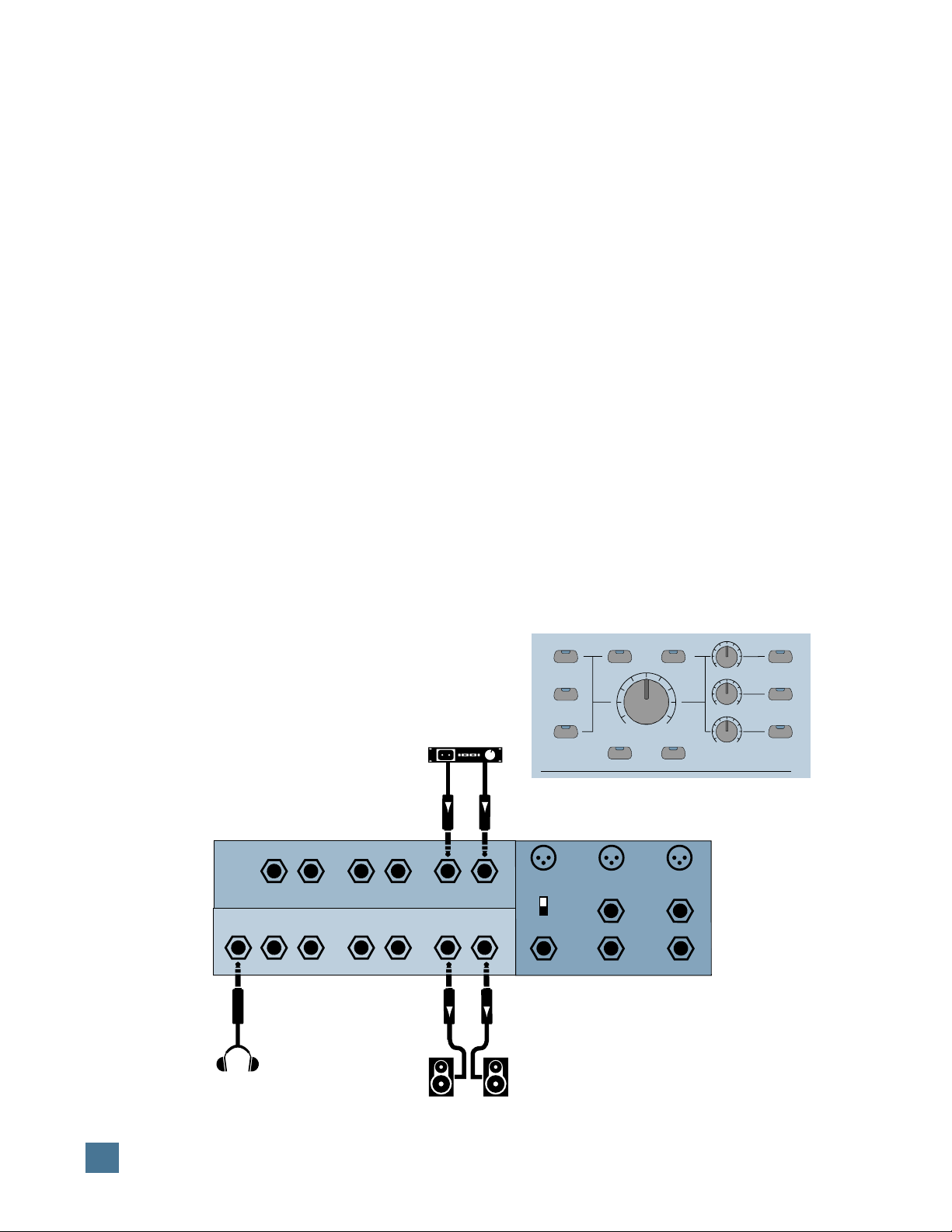
The built-in control room section provides a
convenient way to monitor your mixes without
having to use a separate mixer. It has three
stereo inputs and three stereo outputs, plus a
headphone output. The monitor inputs can be
mixed together, or they can remain discrete,
direct assigned to their corresponding monitor
outputs.
For additional tracking capability, we added
two of our handy studio grade microphone
preamps for direct analog connection to your
digital audio interface’s A/D converters. These
mic pre’s are the same design as those on our
large format recording consoles, and offer
plenty of gain, insert patching, and phantom
power for condenser mics. You can use them for
recording any sound source with low noise, low
distortion, and wide frequency response. To top
it off, we added a third mic preamp for a remote
producer talkback mic or slating capabilities.
You can do so much with HUI. It’s a mix con-
trol surface that sets new levels of interactivity
within today’s and tomorrow’s DAW environ-
ments — it will grow with your system, DAW
software upgrades, etc. HUI can greatly improve
your creativity while diminishing your workload
and the repetitive grind of multiple sessions.
INTENDED USE — WHY HUI?

7
H U I R E F E R E N C E G U I D E
HUI Does What Your DAW Does
Though HUI can do many things, there are
some things it cannot do. If your DAW software
can’t do a particular magic audio trick you’ve
always wished for, neither can HUI*. Because
HUI works along with your DAW — thanks to
the software and MIDI instructions that go
back and forth between HUI and your computer
— it is at your software’s mercy. This is a good
thing, though. If your DAW software is updated
with new features or what have you, HUI can
keep up with the technology. So, though your
software may change, HUI will stay the same.
It’ll let you control your DAW with the hands-
on ease and intuition you expect. It lets you be
as creative as you want to be.
One caveat: Some DAW software packages
accept third party plug-ins. It’s up to the plug-in
designer to insure that their plug-in works cor-
rectly with external controllers like HUI.
HUI SELF-DEMO
Perform the Self-Demo (Optional)
Before you go all the way and connect HUI in
your studio, you can perform this self-demo to
make sure it lights up and works properly, and
to get an idea of what HUI can do.
We’re new-technology fiends just like you are
— we know you want to impress people with
your wise purchase. So set up your HUI on a
tabletop or other such eye-level resting place and
call in the kids, the other studio engineers, or
anyone within shouting distance. We’re going to
plug it in, turn it on, and MAKE IT LIGHT UP!
Just follow these simple directions, okay?
1. With HUI out of the box and propped up
for all to admire, grab the power cord and plug
it in. (Don’t turn it on yet.) We recommend us-
ing a UPS or circuit-protected outlet strip like
the kind you use with your computer or other
audio hardware.
2. Turn on HUI by pressing the rocker
POWER
switch on the rear panel.
3. Within three seconds after turning on the
power, simultaneously press the
CTRL
and
ALT
buttons (located in the “Keyboard Shortcuts”
section at the lower left area of HUI’s front
panel). The self-demo begins, and will continue
as long as HUI is powered up.
Note: You can quit the self-demo at any time
by simply turning off HUI’s
POWER
switch.
HUI SELF-DEMO
* That’s why we didn’t name it “Harry HUIdini.”
An Installation Note
HUI has conductive knobs on the faders that
can “sense” when you touch them and toggle
the “Write” mode for those channels automati-
cally. Furthermore, as soon as you let go of the
knob, the channel goes back into playback
mode, playing back whatever automation had
been previously recorded.
The touch circuits operate by sensing the
stray capacitance your body provides between
the fader knobs and ground. There are a num-
ber of variables that can affect the operation of
this circuit, including temperature, humidity,
and the number of fader knobs touched.
Reliable operation of the touch circuits de-
pends on providing a good earth ground for the
HUI. Be sure the power cord is plugged into a
3-prong outlet with the third pin (safety pin)
connected to earth ground. If you’re not sure
whether the third pin is grounded, use an AC
outlet circuit tester to verify that the outlet is
properly configured (available from Radio
Shack and many fine hardware stores).
DO NOT BYPASS THE SAFETY PIN ON
THE PLUG.

8
H U I R E F E R E N C E G U I D E
MASTER
VOLUME
MUTE
OUTPUT 1
DIM
1:1 DISCRETE MONO
INPUT 1
INPUT 3
INPUT 2
OUTPUT 3/
PHONES
OUTPUT 2
LEVEL 1
LEVEL 3
LEVEL 2
CONTROL ROOM
MAX
CONTROL ROOM
OO
QUICK START
Okay, okay… let’s run some audio through
HUI’s monitor section. If you already performed
the self-demo, then you know the faders work.
The next logical stage is to make sure that HUI
works with audio connected, and with your DAW.
Quick Start Audio Test
The diagram below shows the simple audio
connections you’ll need to make for the audio
quick start.
1. With HUI’s power turned off, plug in one of
the following:
• A pair of powered studio monitors to
MONI-
TOR OUTPUTS 1
on HUI’s rear panel; or…
• A pair of speakers (via a power amp) to
MONITOR OUTPUTS 1
on HUI’s rear panel;
or…
• At the very least, a pair of headphones. You’ll
plug these into — wonder of all wonders —
the
HEADPHONES
jack on HUI’s rear panel.
Now you can hear what’s happening.
2. Connect the output of a stereo audio
source (e.g., tape deck or CD player) to the
L/R
MONITOR INPUTS 1
.
3. Make sure the front panel
MASTER VOL-
UME
and
LEVEL
knobs are off or turned down.
4. Power up HUI by pressing the
POWER
switch on the rear panel.
5. On HUI’s front panel, make sure the
INPUT 1
,
OUTPUT 1
and
OUTPUT 3
buttons are pressed.
They’re in the
CONTROL ROOM
section; their
LEDs will light up. (Be sure the
1:1 DISCRETE
switch is off.)
6. Turn up the
MASTER VOLUME
knob, the
LEVEL 1
knob, and the
LEVEL 3
knob enough
to hear sound coming from the speakers and
headphones.
7. Set the
TALKBACK MIC
switch on the
rear panel to the
INTERNAL
position. With the
TALKBACK LEVEL
knob all the way down,
press and hold the
TALKBACK
button, and
slowly turn the
TALKBACK LEVEL
knob up un-
til you can hear yourself talk in the
headphones.
Note:
TALKBACK
is only assigned to
OUT-
PUT 3/PHONES
from the factory. You can
assign
TALKBACK
to any of the
OUTPUTS
(see instructions under “Talkback Section” on
page 13).
8. Repatch the audio source into various in-
puts and turn on the various front panel input
and output switches accordingly. As a precau-
tion, turn down the
MASTER VOLUME
control while repatching cables. You’re now
checking all of the various input and output
combinations.
More information on HUI inputs and outputs
can be found in the “Audio Input and Output”
section, which begins on page 17.
If you suspect a problem with the HUI, turn
to the “Troubleshooting” section beginning on
page 25 and run the self-test.
3
L/Mono
Headphones
Headphones
R L/Mono R L/Mono
Talkback
Trigger Out
Insert Insert
Out
Mic 2 Mic 1
R
MONITOR INPUTS
MONITOR OUTPUTS
1
3 2 1
Powered Monitors
such as Mackie HR824s
(or connect to a power amp
connected to a set of speakers)
Internal
External
Mic
Tape Deck or CD Player
QUICK START

9
H U I R E F E R E N C E G U I D E
Quick Start DAW Controller Test
In order to make sure HUI is working in con-
junction with your DAW, we’ll perform the next
test. However, a few things need to be set prop-
erly in your system software on your computer:
• Hook up your computer to HUI as shown in
the diagram below.
• Make sure you have OMS (Open Music Sys-
tem) installed (or whatever MIDI software is
compatible with your DAW), active, and
properly configured on your computer.
• Make sure HUI is defined as a device in your
OMS setup (be sure the proper port, chan-
nels, etc., are selected).
Note: Consult your software manual (or
OMS literature) for the specifics on the above-
mentioned OMS-related steps.
• Make sure the interface hardware is turned
on, and the MIDI cables are properly routed
in and out according to the port configura-
tions defined in the MIDI system software
(i.e., OMS).
•Pro Tools Users: Make sure the HUI “per-
sonality file” is placed in the DAE controller
folder in your System folder, and check the
Pro Tools MIDI Controller’s Guide for informa-
tion on OMS setup.
• Make sure HUI is defined as a MIDI control-
ler peripheral in your DAW software.
Next:
1. Run a pair of audio cables from your DAW
audio interface’s outputs to HUI’s
MONITOR
INPUTS 1
(L & R). The plugs on these cables
will depend on what type of jacks (1/4″, RCA,
XLR) you have on your DAW audio interface or
sound card; the HUI ends of these cables
should be 1/4″TRS plugs (TS are okay).
2. You’ll need a previously-recorded session
to demo. Chances are you’ve either already re-
corded some sessions with your DAW and can
use one of those. If you have no session to call
your own, the software CD-ROM should have a
sample session for you to use.
With all the above connections made and
your DAW turned on:
3. Switch on HUI with the
POWER
switch
on the rear panel. Turn on the power amps or
powered monitors last.
4. Start your DAW application.
5. As soon as HUI is defined as a peripheral,
MIDI active sensing is enabled and HUI begins
displaying time code. This is a good thing.
6. Press HUI’s
PLAY
button. (You could also
click on PLAY on your computer screen, but
since we’re testing HUI…). The time code will
change, indicating success.
7. Enable the control room inputs and outputs,
turn up the volume, and dance to the music.
MIDI
Interface
HUI Rear Panel
Computer Connection
MIDI Out MIDI In
3
L/Mono
Headphones
R L/Mono R L/Mono
Talkback
Trigger Out
Insert Insert
Out
Mic 2 Mic 1
R
MONITOR INPUTS
MONITOR OUTPUTS
1
3 2 1
DAW audio interface
Computer
Internal
External
Mic
Serial Port
Expansion
Keyboard In
Keyboard Thru
Mouse In
Mouse Thru
Powered Monitors
such as Mackie HR824s
(or connect to a power amp
connected to a set of speakers)
QUICK START

10
H U I R E F E R E N C E G U I D E
HUI FEATURES AND CONTROLS
Front Panel (Control Surface)
Channel Strip
NOTE: The functions of some of these switches
depend on your particular DAW software. There-
fore, you may wish to consult your DAW manual
for further details.
1Rec/Rdy (Record/Ready) switch. This
switch arms or disables the channel for recording.
2Insert switch. This switch calls up inserts
for editing, and also allows you to bypass all in-
serts on the channel when the master
BYPASS
switch is pressed (see bo at right). Makes it easy
to access DSP (digital signal processing) soft-
ware additions. (In Pro Tools these are called
Plug-Ins.)
3V-Sel switch. This switch toggles be-
tween the various functions of the
V-Pot, such as I/O routing assign-
ment, Send Mute switching (when
the master
MUTE
switch is en-
gaged), and Select when applying
the default function.
4Pan/Send V-Pot™. This
“soft” potentiometer is used to
adjust the send level and pan, to
choose items from scrollable I/O
assignment lists, and to deter-
mine destinations for sends.
5Auto switch. For enabling
automation on the channel.
6Solo switch. For isolating
a channel’s signal.
7 Mute switch. For defeat-
ing the track’s signal.
8Scribble strip. A four-
character LED dot-matrix display
for the channel’s name, group
membership status, input and
output source for the channel,
send and insert status, and pre/
post status display for sends.
Names are entered in the DAW
software.
9Select switch. This switch
is used to choose a channel for
channel-based editing or assign-
ment commands, such as groups,
assignment, etc.
bl Touch-sensitive motor
faders. These 100mm faders are
for controlling the channel’s lev-
els, aux returns, MIDI track, and
master fader levels. The eight
faders move relative to the activ-
ity of the currently chosen bank
of on-screen faders.
bm Dual LED ladders. (Not shown here.)
Display mono or stereo audio levels, according
to the DAW specifications. The Clip LED comes
on at 0dBFS.
For Pro Tools users: When a channel is desig-
nated as mono, only the left meter ladder lights
up. Likewise, if the channel is being used as a
stereo channel, both ladders operate. (These
meters are located in the meter bridge directly
above each channel strip.)
Left Control Strip
bn Rec/Rdy All switch. This switch is used
to enable (or defeat) all tracks for recording.
bo Bypass switch. This switch allows you
to bypass any channel inserts (hardware or
DSP Plug-Ins) on any HUI channel(s) you have
selected.
bp Select/Assign
switches and scribble
strip. These switches are
used to globally deter-
mine what a track’s V-Pot
will control. Included in
this section are:
SENDS
A–E
,
PAN
,
MUTE,
and
SHIFT.
The scribble strip
shows what the
V-POT
is
doing, as well as send
destination and I/O rout-
ing of an individual
channel strip.
bq Suspend/Default
switches.
SUSPEND
temporarily suspends all
automation functions
(globally).
DEFAULT
is
used to set selected
channel(s) back to the
original, default settings.
Use the
DEFAULT/SE-
LECT
9 switches to
reset faders, and the
DEFAULT/V-SEL
3
switches to reset sends
and pans.
br Input/Output/As-
sign switches. These
switches are used for sig-
nal routing assignment(s).
By selecting combina-
tions of these switches
and the
SELECT
and
V-SEL
switches, channel
I/O and send (bus) I/O
assignments are made.
REC/RDY
INSERT
V-SEL
MUTE
SOLO
AUTO
SELECT
PAN/SEND
CHANNEL
BANK
ASSIGN
SELECT- ASSIGN
KEYBOARD SHORTCUTS
WINDOW
SHIFT/ADD
CTRL/CLUTCH
OPTION/ALL
EDIT MODE EDIT TOOL
UNDO SAVE
ALT/FINE
EDIT
MIX
STATUS
TRANSPORT ALT
MEM-LOC
SEND B
SEND C
SEND D
SEND E
PAN
SEND A REC/RDY ALL
BYPASS
MUTE
SHIFT
ASSIGN
DEFAULT
OUTPUT
INPUT
SUSPEND
HUI FEATURES AND CONTROLS

11
H U I R E F E R E N C E G U I D E
bs Channel/Bank select switches. Scroll
switches to move back and forth across fader
channels on the DAW mixing window.
CHANNEL
scrolls one channel at a time,
BANK
scrolls
eight channels at a time.
bt Window switch matrix. These switches
allow you to select various DAW windows.
Pressing any switch will bring that window to
the foreground on your computer screen.
bu Keyboard Shortcuts switch matrix.
The four upper switches match other shortcut
or software menu modes in your DAW, while
the four lower “alternate function” switches
emulate their computer keyboard counterparts.
DSP Edit/Assign Section
NOTE: The functions of some of these switches
depend on your particular DAW software. There-
fore, you may want to consult your DAW manual
for further details.
140 x 2 VFD display. Located in the
meter bridge, this 40-character wide by 2-line
VFD (vacuum fluorescent display) shows up to
four Plug-Ins or up to eight Plug-In parameters.
The VFD is also used to display general HUI info.
Note: You can adjust the brightness of the
VFD by pressing and holding the OPT/ALL
switch and repeatedly pressing the INSERT/
PARAM switch. This toggles among four levels
of brightness.
2Assign/Compare/Bypass switches.
The
ASSIGN
switch allows you to assign a
DSP addition (or Plug-In) to a channel strip;
COMPARE
allows you to compare the current
DSP parameter setting with the previous one;
and
BYPASS
allows you to bypass DSP param-
eters or any DSP additions assigned to the
channel, as applicable.
3Insert/Param(eter) switch. Allows you
to toggle the
VFD
between the DSP addition as-
signed to a particular insert, or the DSP
addition parameters (for editing).
4Scroll control. Used in conjunction with
the
INSERT/PARAM
switch, it either toggles
the
VFD
between Inserts 1-4 and Insert 5, or
scrolls through control parameter pages for the
currently active DSP addition.
5Select switch and V-Pot™. These V-
Pots and Select switches allow you to assign
Plug-Ins and edit Plug-In parameters corre-
sponding to the VFD and software screen
displays.
SELECT SELECT SELECT
SCROLL
DSP EDIT/ASSIGN
INSERT
PARAM
SELECT SELECT
COMPARE
ASSIGN
BYPASS
Welcome to --- HUI--- by MACKIE DESIGNS
Firmware version 1.0
HUI FEATURES AND CONTROLS

12
H U I R E F E R E N C E G U I D E
Switch Matrix Section
NOTE: The functions of some of these switches
depend on your particular DAW software. There-
fore, you may want to consult your DAW manual
for further details.
This section contains switches for global au-
tomation enabling, mode selection, group
creation, and more.
1Function (“F”) keys. These keys pro-
vide a number of special functions relating to
the operation of the HUI. Refer to the table on
page 31 in the “Specifications” section for de-
tails.
2Auto Enable switches. These switches
globally enable automation for
FADER
,
MUTE
,
PAN
,
SEND
,
PLUG IN
, and
SEND MUTE
.
3Auto Mode switches. These switches
arm (or disable) automation on individual chan-
nels or channel groups. Options are
READ
,
TOUCH
,
LATCH
,
WRITE
,
TRIM
, and
OFF
.
4Status/Group switches. These switches
are used to query automation, monitor, and
group status, and to create and change groups.
They include
AUTO
,
GROUP
,
MONITOR
,
CRE-
ATE
,
PHASE
, and
SUSPEND
.
5Edit switches. These switches perform
standard editing functions, including
CAP-
TURE
,
SEPARATE
,
CUT
,
COPY
,
PASTE
, and
DELETE
.
6Time Code Display and mode LEDs.
Shows current time location in either time
code, feet, or beats. LEDs indicate which mode
is being displayed. If no LED is lit, the display
is in standard minutes/seconds mode.
Note: Once communication is established be-
tween HUI and the DAW software, the decimal
point in the lower right corner of the Time Code
Display blinks (once per second). If incoming
MIDI communication is disrupted for any reason,
the Time Code Display will read “Off Line.”
7Rude Solo Light. A gentle reminder that
a channel (or channels) in your mix session is
soloed, whether it’s part of the current bank of
eight channels or not.
8Locate/Numerics keypad. Equivalent to
its computer keyboard counterpart.
Control Room Section
The features found in this parcel of real es-
tate (pictured on the next page) were included to
let you use HUI without having to dedicate a
mixer to monitoring functions. You can control
input and output sources, as well as master
volume, from this section. With the talkback
features you can slate takes or talk to the voice
talent, either with the in-panel talkback mic or
with an external mic plugged into HUI’s back-
side. We’re sure you’ll find these features quite
useful in your daily DAW work. (See page 18
for more info.)
AUTO
PLUG IN SEND MUTE
TRIM
OFF PHASE SUSPEND
PAN SEND LATCH WRITE MONITOR CREATE
PASTE
CUT
FADER
MUTE
READ TOUCH GROUP CAPTURE
DELETE
COPY
SEPARATE
AUTO ENABLE AUTO MODE EDITSTATUS/GROUP
TIME CODE
FEET
RUDE
SOLO
LIGHT
BEATS
LOCATE/NUMERICS
F6 F7
F1 F2 F3 F4 F5 F8/ESC
-
+
CLR
*
=
/
7 8 9
4 5 6
1 2 3
0
E
N
T
E
R
.
HUI FEATURES AND CONTROLS

13
H U I R E F E R E N C E G U I D E
1Input source select switches. These
switches allow you to monitor whichever stereo
input sources you have selected. Labeled
IN-
PUT 1
,
INPUT 2,
and
INPUT 3
, they correspond
to the
MONITOR INPUTS 1, 2, and 3
jacks on
HUI’s rear panel.
21:1 Discrete switch. This switch deter-
mines whether HUI’s inputs act as three stereo
pairs assignable to any stereo output, or as six
discrete mono inputs assigned to their corre-
sponding outputs only (used for
surround-sound mixing).
3Mono switch. When this switch is en-
gaged, HUI sums all signals through the
MASTER VOLUME
control into one mono signal.
4Master Volume control. This level con-
trol determines the overall level of the currently
selected monitor source(s).
5Output level controls. Each one of these
controls adjusts the output level of its respec-
tive audio output pair.
6Output select switches. These switches
determine which monitor outputs are being
used. Labeled
OUTPUT 1
,
OUTPUT 2,
and
OUTPUT 3/PHONES
, they correspond to the
MONITOR OUTPUTS 1, 2, 3
and
PHONES
jacks on HUI’s rear panel.
7Mute and Dim switches. Out of the box, the
MUTE
switch mutes all three
MONITOR OUT-
PUTS
(including
PHONES
), while
DIM
lowers
HUI’s monitor output level by a set amount (de-
fault is 20dB).
To assign mute and dim control to specific out-
puts, press and hold the
OPTION/ALL
and
MUTE
or
OPTION/ALL
and
DIM
switches. The
LEDs in the
OUTPUT
assign switches begin
blinking to indicate which
OUTPUTS
are as-
signed to that particular
function. Press an
OUTPUT
switch to toggle the
MUTE
or
DIM
assignment on and off.
When it’s set the way you
want, press and hold the
OPTION/ALL
and
MUTE
or
OPTION/ALL
and
DIM
switches again to quit.
To change the amount of
dim level (i.e., more or less
than the default 20dB), press
and hold the
OPTION/ALL
and
DIM
switches to enter
the Dim Assignment Mode
(make sure the
DIM
switch
is turned on first if you want
to monitor the dim level as
you adjust it). Turn the
SCROLL
knob left or
right to adjust the dim level, which appears in
the VFD in 1dB increments. (The
SCROLL
knob
is located on the front panel, in the upper right
corner beneath the
INSERT/PARAM
switch.)
Note: For more on how
MONITOR INPUTS
and
OUTPUTS
work with HUI’s surround-sound ca-
pabilities, see pages 17 and 23.
Talkback Section
8Talkback level control. This controls the
level of the internal (panel) talkback mic only.
9Talkback panel mic. This on-board mic
allows you to communicate with the talent,
slate take numbers into your session, etc.
Note: Be sure the INTERNAL/EXTERNAL
select switch on the rear panel is set to INTER-
NAL when using the panel mic.
bl Talkback Enable switch. This switch
turns on/off the talkback panel mic circuit on
both the panel mic and external talkback mics.
Press and hold this switch to talk, and the red
LED in the switch lights to indicate the talkback
function is active. If using the
REMOTE TALKBK
TRIGGER
jack on the rear panel to turn the
talkback mic on and off, the red LED in the switch
lights when the talkback function is active.
To route talkback assignment (it’s routed only
to
OUTPUT 3/PHONES
as a default), press
and hold the
OPTION/ALL
and
TALKBACK
switch. The LEDs in the
OUTPUT
assign switches
begin blinking to indicate which
OUTPUTS
are
assigned to the
TALKBACK
function. Press an
OUTPUT
switch to toggle the
TALKBACK
as-
signment on and off. When it’s set the way you
want, press and hold the
OPTION/ALL
and
TALKBACK
switches again to quit. Of course,
beware of feedback situations!
TALKBACK
MASTER
VOLUME
MUTE
OUTPUT 1
DIM
1:1 DISCRETE MONO
INPUT 1
INPUT 3
INPUT 2
OUTPUT 3/
PHONES
OUTPUT 2
LEVEL 1
LEVEL 3
LEVEL 2
CONTROL ROOM
MIC
LEVEL
MAX
CONTROL ROOM
OO
HUI FEATURES AND CONTROLS

14
H U I R E F E R E N C E G U I D E
Transport Section
NOTE: The functions of some of these switches
depend on your particular DAW software. There-
fore, you may want to consult your DAW manual
for further details.
1Transport switches.
The top row of transport switches includes
AUDITION
,
PRE
,
IN
,
OUT
, and
POST
. These
switches allow you to set up punch-in/punch-
out and playback locations.
•
AUDITION
lets you play back the section
you’ve designated for punch-in/punch-out.
•
PRE
sets up the amount of “pre-roll” before
the actual punch-in point.
•
IN
marks the point at which the punch-in
will begin.
•
OUT
marks the point at which the punch-in
will end (i.e., the “punch-out” point).
•
POST
sets up the amount of “post-roll” after
the punch-out point.
The second row of Transport switches in-
cludes:
RTZ
,
END
,
ONLINE
,
LOOP
, and
QUICK PUNCH
.
•
RTZ
returns the playback cursor in your
DAW to the beginning of the session (or
0/zero).
•
END
moves the playback cursor in your
DAW to the end of the session.
•
ONLINE
is used to bring your DAW online
(or to take it offline), and indicates online status.
•
LOOP
allows you repeatedly play back a
section of your DAW session.
•
QUICK PUNCH
allows you to use your
DAW’s “quick punch” feature.
Similar to the transport buttons on a tape re-
corder or in your DAW, the third row of
transport switches includes
REWIND
,
FAST
FWD
,
STOP
,
PLAY
, and
RECORD
.
2Mode/Arrow switches. These switches
are used to navigate, zoom, and make selec-
tions in the waveform display. When
MODE
is
toggled, the arrow keys act as horizontal/verti-
cal view expander/contractors. When
MODE
is
disabled, the arrow keys can be used as a cur-
sor location device, similar in function to tab
and arrow keys on a computer keyboard.
3Jog Wheel. This optical encoder wheel
performs many functions (depending on your
DAW). Because its function is determined by
your DAW, we refer you to your DAW controller
manual.
4Scrub/Shuttle switches. These switches
control the function of the jog wheel. Again, re-
fer to your DAW controller manual for their
specific functions.
FAST FWD STOP PLAY RECORD
MODE
REWIND
SCRUB
SHUTTLE
AUDITION
RTZ
PRE
END
IN
ON LINE
OUT
LOOP
POST
QUICK PUNCH
HUI FEATURES AND CONTROLS

15
H U I R E F E R E N C E G U I D E
MONITOR OUTPUTS
MONITOR INPUTS
PHONES
MOUSE
KEYBOARD
SERIAL PORT
EXPANSION
IN
ON
OFF
THRU
IN THRU
MIDI IN
POWER MIDI OUT
L/MONO
SERIAL NUMBER MANUFACTURING DATE
RISK OF ELECTRIC SHOCK
DO NOT OPEN
REPLACE WITH THE SAME TYPE FUSE AND RATING.
DISCONNECT SUPPLY CORD BEFORE CHANGING FUSE
UTILISE UN FUSIBLE DE RECHANGE DE MÊME TYPE.
DEBRANCHER AVANT DE REMPLACER LE FUSIBLE
WARNING:
TO REDUCE THE RISK OF FIRE OR ELECTRIC SHOCK, DO NOT
EXPOSE THIS EQUIPMENT TO RAIN OR MOISTURE. DO NOT REMOVE COVER.
NO USER SERVICEABLE PARTS INSIDE. REFER SERVICING TO QUALIFIED PERSONNEL.
CAUTION
AVIS:
RISQUE DE CHOC
É
LECTRIQUE — NE PAS OUVRIR
1
2
3
RL
1
2
3
R
RS232
RS422
FOOTSWITCH
IN
RELAY
OUT
1 2
1 2
CONCEIVED, DESIGNED, AND MANUFACTURED BY MACKIE DESIGNS INC • WOODINVILLE • WA • 98072 • USA • MADE IN USA • FABRIQUE AU USA • PATENTS PENDING
COPYRIGHT ©1997 • THE FOLLOWING ARE REGISTERED TRADEMARKS OF MACKIE DESIGN INC.: "MACKIE", HUI, AND THE "RUNNING MAN" FIGURE •
120V, 60Hz, .85A
FUSE 1.25A, 250V SLOW
MACKIE DESIGNS THIS DEV ICE COMPLIES WITH PART 15 OF THE FCC RULES. OPER ATION IS SUBJECT TO THE FOLLOWING TWO CONDITIONS: 1) THIS DEVICE MAY NOT CAUSE HARMFUL INTERFERENCE AND 2) THIS DEV ICE MUST ACCEPT ANY INTERFERENCE RECEIVED THAT MAY CAUSE UNDESIRED OPERATION
Rear Panel
Controller Input/Output Section
1Power cord receptacle and Power
switch. The power cord receptacle is a stan-
dard IEC connection for HUI’s power cord.
Before plugging the power cord into an AC out-
let, be sure it is firmly seated in the receptacle.
Note: For safety reasons, the AC outlet must
be a “3-prong” outlet with hot, neutral, and
ground terminals. Do not bypass the plug’s
ground pin! In addition to the safety issue, this
insures that the HUI’s chassis is properly
grounded which is required for reliable opera-
tion of the faders’ touch circuits.
2MIDI In/Out Connectors. These are
standard MIDI 5-pin DIN ports for connecting
HUI to your MIDI interface. (Note: HUI must be
connected to a dedicated MIDI input and out-
put pair; these connectors cannot be merged or
daisy-chained.)
3Keyboard/Mouse ADB ports. Conve-
nient in/out throughput jacks for direct parallel
connection of your ADB (Apple Desktop Bus)
computer keyboard and mouse. These are used
for extending the reach of your keyboard and
mouse between your computer and HUI, not for
actual control. See page 19 for more information.
4Serial port, RS-232/422 switch. The
serial port is a standard 9-pin D-Sub connector
for connecting HUI to the external DAW. The
switch selects between RS-232 and RS-422
operation (the data stream is equivalent to MIDI).
See page 19 and page 31 for pin out and other
specifications.
5Expansion Port. 9-pin D-Sub connector for
future connection of external control devices.
6Footswitch Input jacks. Allows you to use
an external footswitch to toggle DAW functions
such as loop, play, and record modes.
7Relay Output jacks. Used to toggle ex-
ternal circuits for solo indication, “on-air”
lights, recording lights, etc. See page 31 in the
“Specifications” section for a block diagram of
these jacks.
Analog Audio Input/Output Section
8Monitor Inputs (x3). These six line-
level inputs (balanced or unbalanced) feed the
control room section. They can be used either
as three stereo pairs or as six discrete inputs.
9Monitor Outputs (x3). These six line-
level outputs (balanced or unbalanced) from the
control room section can be used either as three
stereo pairs or as six discrete outputs.
bl Headphones jack. This is where you plug
in your stereo headphones. Its signal is shared
with (as well as isolated from)
MONITOR OUT-
PUT 3
, so the phones may be plugged in
simultaneously.
HUI FEATURES AND CONTROLS

16
H U I R E F E R E N C E G U I D E
MIC 1
OUT
BAL /
UNBAL
OUT
BAL /
UNBAL
INSERT
TRIM
TRIM
REMOTE
TALKBK
TRIGGER
INTERNAL
EXTERNAL
MIC
INPUT
MIC
INPUT
+48V
PHANTOM
+48V
PHANTOM
+48V
PHANTOM
MIC
INPUT
TRIM
MIC 2
MIC
TALKBACK
060 dB 60 dB 60 dB0
0
IN
OUT
INSERT
IN
OUT
G
A
I
N
G
A
I
N
G
A
I
N
Direct out with no signal interruption to output.
Insert only to first “click.”
Channel Insert jack
Channel Insert jack
Channel Insert jack
Direct out with signal interruption to output.
Insert all the way in to the second “click.”
For use as an effects loop.
(TIP= SEND to effect, RING = RETURN from effect.)
TS PLUG
TS PLUG
TRS PLUG
“tip”
This plug connects to one of the
mixer’s Channel Insert jacks.
“ring”
tip
ring
sleeve
SEND to processor
RETURN from processor
(TRS plug)
Insert Jack Options
Insert Jack “Y” Cable
Talkback and Mic Preamp
Section
Another great thing about HUI —
if we don’t mind saying so our-
selves — is its talkback and mic
preamps. They allow you to add
a vocal track, insert slating in-
structions, and perform other
handy tasks, without having to
resort to an outboard mixer.
1Mic preamp Trim control.
Used to set initial gain stage for
mic signal levels (Mic 1, Mic 2,
and Talkback). Trim level from
mic level (60dB down) to Unity
(0dBu). Maximum input is +22dBu.
2Phantom Power switch.
Push this switch to provide 48V
of low-current DC to power
condenser mics.
3Talkback XLR mic input.
Used to connect an external talk-
back mic. Note that there is no
dedicated output for this preamp,
although talkback logic routing
will send the signal to any or all of
the
MONITOR OUTPUTS
(front
panel assignable — see instructions
for the Talkback Enable switch bl
on page 13).
4Mic Internal/External switch. Switches
talkback signal source between the front in-panel
mic or an external talkback mic plugged in here.
5Remote Talkback Trigger jack. The
talkback circuit is bidirectional — it can either
trigger something or be triggered by something.
To remotely trigger HUI’s talkback function, con-
nect a normally-open on/off footswitch to this jack.
This is for the producer who loves to sit com-
fortably back and communicate with the talent
during crucial moments in a recording session.
Conversely, if the engineer wants to enable
another console’s talkback function via the HUI
front panel talkback switch, connect a TS cable
between this jack and an unbalanced destina-
tion jack. When the front panel talkback switch
is pressed (enabled), the line is pulled “low.”
See page 31 for a diagram of this circuit.
6XLR mic inputs. These are two of
Mackie’s high-headroom, low-noise mic
preamps. Intended for mic-level inputs only,
they offer plenty of gain and sonic clarity.
7Inserts. 1/4″TRS insert jacks for using
in-line external effects and signal processing
with TRS to TS send and TS return “Y” cables.
These connectors can also be used as direct
outputs using a 1/4″TS plug pushed in all the
way (interrupting the audio signal completely),
or only to the first click, which does not inter-
rupt the audio (see “Insert Jack Options”
figure). The latter method allows you to use the
insert as a direct out in combination with the
mic output described next.
8Outputs. 1/4″TRS jacks for routing your
microphones to external sources, such as the
DAW audio interface for recording. These line-
level outputs will provide either balanced and
unbalanced signals.
HUI FEATURES AND CONTROLS

17
H U I R E F E R E N C E G U I D E
MASTER
VOLUME
MUTE
OUTPUT 1
DIM
1:1 DISCRETE MONO
INPUT 1
INPUT 3
INPUT 2
OUTPUT 3/
PHONES
OUTPUT 2
LEVEL 1
LEVEL 3
LEVEL 2
CONTROL ROOM
MAX
CONTROL ROOM
OO
MASTER
VOLUME
MUTE
OUTPUT 1
DIM
1:1 DISCRETE MONO
INPUT 1
INPUT 3
INPUT 2
OUTPUT 3/
PHONES
OUTPUT 2
LEVEL 1
LEVEL 3
LEVEL 2
CONTROL ROOM
MAX
CONTROL ROOM
OO
Stereo
Input 1 on
(switched OFF)
1:1 DISCRETE Monitor Mode
STEREO Monitor Mode
(Stereo
Input 3 off)
Stereo
Input 2 on
Input 1
(mono pair)
Input 3
(mono pair)
Input 2
(mono pair)
Output 1 controls
Input 1 only
Output 3 controls
Input 3 only
Output 2 controls
Input 2 only
(Output 1
switched off)
Output 3 on;
signals 1 & 2
mixed
Output 2 on;
signals 1 & 2
mixed
(switched ON)
AUDIO INPUT AND OUTPUT
Signal Flow Primer
Monitoring the audio signals can be done in
either mono, stereo, or surround-sound (with
six discrete channels). The overall input vol-
ume is controlled by the
MASTER VOLUME
knob. The outputs are controlled by three sepa-
rate output level controls and toggle switches
(labeled
OUTPUT 1, 2,
and
3
). HUI uses DCAs
(digitally controlled amplifiers) to control in-
ternal signal flow completely independent of
the DAW. The signal is distributed according to
which inputs and outputs are enabled.
Stereo Monitor Mode — enabled inputs’ stereo
signals are
summed
into one stereo signal
In stereo monitor mode — with the
1:1 DIS-
CRETE
switch turned off — any of the three
stereo input sources may feed any of the stereo
MONITOR OUTPUTS
(
OUTPUT 1, 2, and 3
).
Any or all of the three stereo inputs can be
monitored simultaneously. That is, it’s up to you
to disengage an input if you don’t want to moni-
tor it. Any and all of the
OUTPUTS
can be
active at once, so you can send outputs to vari-
ous pairs of speakers and various combinations
of speaker pairs and recorders.
AUDIO INPUT AND OUTPUT
1:1 Discrete Monitor Mode — enabled inputs are
not
summed
When HUI’s
1:1 DISCRETE
switch is engaged
(the LED will light), the control room section be-
comes a discrete surround matrix capable of
either standard 4.1 surround (L/R/Center/Sur-
round/subwoofer), or 5.1 surround (L/R/Center/
Surround L/Surround R/subwoofer).
You can set up your DAW audio output con-
figuration so that the various “stem” outputs
correspond to the physical outputs on the DAW
audio interface. These outputs are then patched
to HUI’s
MONITOR INPUTS 1, 2, and 3
.
With
1:1 DISCRETE
engaged, the output
LEVEL
controls for
OUTPUTS 1, 2, and 3
act as
trims for the respective mix stems (L/R/Center/
Surround L/Surround R/subwoofer). The
MAS-
TER VOLUME
controls the level for all three
output pairs, allowing you to trim the overall
level of separate surround amp feeds.
Keep in mind that, when in discrete mode,
output pairs share a common stereo level con-
trol and individual outputs cannot be adjusted
independently.
Note: The
DIM
and
MUTE
controls operate
on all outputs, regardless of whether HUI is in
discrete mode.
MONO
, too, sums all inputs to-
gether, regardless of mode. Refer to the audio
block diagram on page 30 for further info.

18
H U I R E F E R E N C E G U I D E
AUDIO INPUT AND OUTPUT
Momentary Footswitch
(optional)
Studio
Mic 2 Studio
Mic 1
Talkback
Mic
Compressor
Talkback
Trigger Out
Insert Insert
Out
Mic 2 Mic 1
DAW audio interface
Internal
External
Mic
Analog Audio Connections
Microphones
HUI has two stand-alone microphone pream-
plifiers for connecting mics for use during
recording. These mic preamps are of the same
high-headroom, low-noise design found on
Mackie’s celebrated 8•Bus and SR Series mix-
ing consoles. Because we know you don’t want
to run your quality mics through second-rate
preamps, we use preamps with large-emitter-ge-
ometry, conjugate-pair transistors, allowing them
to sound as good as the preamps on the most
expensive consoles.
Connect your mics to the HUI preamps by
using an appropriate cable with XLR connec-
tors. (Pin 1=Shield [Ground], Pin 2=Signal
High [+], Pin 3=Signal Low [–].)
Adjusting the Mic Trim Control
To get the best signal-to-noise ratio, it is im-
portant to set the
MIC TRIM
controls properly.
1. Connect the microphone to the
MIC IN-
PUT
connector. Push in the
+48V PHANTOM
switch if required for your microphone.
2. Turn the
TRIM
level control all the way
down (counterclockwise).
3. Disconnect any external gear connected
to the
INSERT
jack.
4. Connect the
BAL/UNBAL OUT
connector
to the input of the DAW audio interface. En-
gage the Rec/Rdy function on that channel,
and set its input level to unity gain.
5. Make appropriate “noise” into the micro-
phone. For example, have a performer play/
sing/strike something or someone, etc. at the
level they’re going to record or perform. Don’t just
play a single sustained note, but rather, jam away
as you would during a recording or performance.
You might want to roll an already-recorded
track from your recorder.
6. Adjust the
TRIM
level control. The goal is
to produce the highest signal level possible
without distorting the mic preamp stage, and
to attain the highest bit level when the analog
signal is converted to digital, without exceed-
ing the maximum digital value (which results
in digital clipping). As a general rule, you want
the meter on the DAW audio interface to read at
or around –15 dB. The peaks should regularly
hit, and occasionally exceed, the –15 dB desig-
nation on the meter.
7. If you connect an external processor to
the INSERT jack, you may need to readjust the
input level control for the DAW audio interface.
Talkback Mic
Though HUI has its own talkback mic on the
front panel, you may want to connect an exter-
nal talkback mic of your own. That’s why we’ve
included a talkback mic preamp on the rear
panel. This mic preamp is identical to the other
two mic preamps (described above), giving you a
total of three high-quality mic inputs. Connect
your external talkback mic the same way you
would the other mics. Be sure the talkback
TRIM
control is turned up (adjust to taste).
The
MIC INTERNAL/EXTERNAL
switch on
HUI’s rear panel lets you choose between the
front in-panel mic or an external talkback mic.
Be sure it is switched according to your needs.
Monitor Outputs
To connect studio monitors (like a pair of
Mackie’s HR824s) to HUI, simply connect one
end of your cables (with 1/4″TRS plugs) into
MONITOR OUTPUT 1
(the left one is for Left
speaker or mono output; right is for Right
speaker output), and the other ends to your
studio monitors.
HUI features three pairs of monitor output
jacks, so you can run up to three sets of monitors
at one time. You may have one set of monitors
in your control room, and one or two others
running to various other places like vocal
booths or the like. Or you may want to audition
your mixes through three different types of
speakers (monitors).

19
H U I R E F E R E N C E G U I D E
DIGITAL CONNECTIONS
These outputs are designed for monitoring
purposes. We do not recommend mixing through
this output section due to the possibility of
feedback routing, and to the fact that smooth
fades, if applicable, may experience some “zip-
pering” inherent to digitally controlled amplifiers
(DCAs). Although these are high quality DCAs,
they are not volume smoothed (interpolated)
between their discrete volume levels. The volume
taper is mapped to resemble the taper of our
analog mixer rotary pots.
DIGITAL CONNECTIONS
MIDI
In order to operate, HUI must be connected
to a MIDI interface. The MIDI interface is in
turn connected to the external computer used
with your DAW.
Connect HUI to a MIDI interface by connect-
ing one MIDI cable between HUI’s
MIDI IN
port and the interface’s MIDI OUT port. Like-
wise, the other cable should be connected
between HUI’s
MIDI OUT
port and the
interface’s MIDI IN port. Now HUI and your
MIDI interface can talk to each other, compare
recipes, and share football scores.
RS-232/RS-422 Serial Port
To use HUI in conjunction with a computer,
run a cable with a 9-pin D-Sub connector from
HUI’s
SERIAL PORT
to the computer’s COM port.
The serial port on HUI bidirectionally trans-
fers data between a computer’s RS-232 or
RS-422 serial port and HUI. The only difference
between using the
SERIAL
and
MIDI
ports is the
rate of transmission of the data (the serial port
operates at 38.4K Baud and MIDI operates at
31.25K Baud) and the general physical hard-
ware (9-pin D-Sub vs. 5-pin DIN, respectively).
The actual data transferred is the same.
For RS-232: Pin 2=TXD
Pin 3=RXD
Pin 5=Ground
For RS-422: Pin 2=TX–
Pin 3=RX+
Pin 4=Ground
Pin 7 =TX+
Pin 8=RX–
Use the following serial communications
parameters when using the
SERIAL
port:
Baud rate: 38.4K
Parity: None
Data bits: 8
Stop bits: 1
Keyboard (computer)
You can “extend ” the use of your computer’s
keyboard by connecting the keyboard to HUI.
Simply connect a 4-pin ADB cable from your
keyboard to HUI’s
KEYBOARD IN
jack. Run
another 4-pin ADB cable from your computer to
HUI’s
KEYBOARD THRU
jack. Now your key-
board can be in closer proximity to HUI.
Note: This extra feature is not required in
order to use HUI — it is there as a convenience
to those who may need the extra length. The
ADB specification limits the ADB cable length
to 5 meters (about 16 feet).
Mouse
Similarly, you can extend the use of your
mouse (or trackball if you’re supremely cool) by
connecting it to HUI. Although most Apple
computers allow you to connect the mouse di-
rectly to the keyboard, some models have more
than one ADB connector on the computer. Using
a 4-pin ADB cable, connect one end to your com-
puter and the other to HUI’s
MOUSE THRU
jack. Then run another 4-pin ADB cable from
HUI’s
MOUSE IN
jack to your mouse or
trackball. (You’ll probably be using the cable
that is hardwired to your mouse — if you use a
trackball you’ll need a separate cable.)
You can use the MOUSE I/O to extend a sec-
ond keyboard/mouse to another computer,
which you might use for sequencing or some
other purpose.
A note regarding ADB port and MIDI com-
munication: HUI communicates with the host
DAW through the MIDI IN/OUT connectors.
The mouse and computer keyboard communi-
cate with the DAW through the ADB connectors.
The Mouse and Keyboard IN/OUT connectors
are wired straight-through, so there is no direct
interaction with the HUI, MIDI or SERIAL ports.
Even though both the HUI and the computer
keyboard have common modifier switches such
as SHIFT, OPTION, ALT, CONTROL, F-keys,
etc., the DAW determines how these keys oper-
ate and interact with one another. For example,
pressing the SHIFT/ADD button on the HUI in
conjunction with a mouse click may not work
the same as pressing the SHIFT key on the
keyboard in conjunction with a mouse click.
Expansion Port
This port is nestled on HUI’s backside for
use with future products.

20
H U I R E F E R E N C E G U I D E
Footswitch
Play ON/OFF
Footswitch
Record ON/OFF
Note: The Footswitch In and Relay Out
operations are defined by the DAW
software (see DAW MIDI Controller's Guide).
This figure shows one example
of how they might be used.
For
Future Products
Mouse
Mouse
MIDI Interface
Computer Serial Connection
To Computer
Serial Port
(Optional)
To 2nd
Computer
Keyboard
Po r t
To Computer
Keyboard
Po r t
(example: triggered by RECORD switch)
Keyboard
2nd Keyboard/Mouse (optional)
MIDI OUT
Keyboard Thru
Keyboard In
Mouse Thru
Mouse In
Serial Port
Expansion
Relay Out
Footswitch In
Computer 2nd Computer (optional)
RECORDING IN PROGRESS
(example: triggered by PLAY switch)
ON THE AIR
MIDI IN
12
Typical System Hookup
DIGITAL INPUT AND OUTPUT
Table of contents
Other Mackie Music Mixer manuals

Mackie
Mackie 1220 User manual

Mackie
Mackie 8-BUS Series User manual

Mackie
Mackie CFX MKII User manual

Mackie
Mackie 1202-VLZ3 User manual

Mackie
Mackie 402-VLZ3 User manual

Mackie
Mackie ONYX 1220i User manual

Mackie
Mackie DS3232 Digital Snake User manual

Mackie
Mackie 802-VLZ3 User manual

Mackie
Mackie TT24 Quick start guide

Mackie
Mackie Onyx 820i User guide

Mackie
Mackie DL806 User manual

Mackie
Mackie 2404 VLZ3 4-Bus User manual

Mackie
Mackie 402VLZ4 User manual

Mackie
Mackie 1604VLZ4 User manual

Mackie
Mackie DIGITAL XBUS - SOFTWARE User manual

Mackie
Mackie 1620 User manual

Mackie
Mackie SR24 4 User manual

Mackie
Mackie PPM1008 User manual

Mackie
Mackie 1402-VLZ3 User manual

Mackie
Mackie XITE User manual