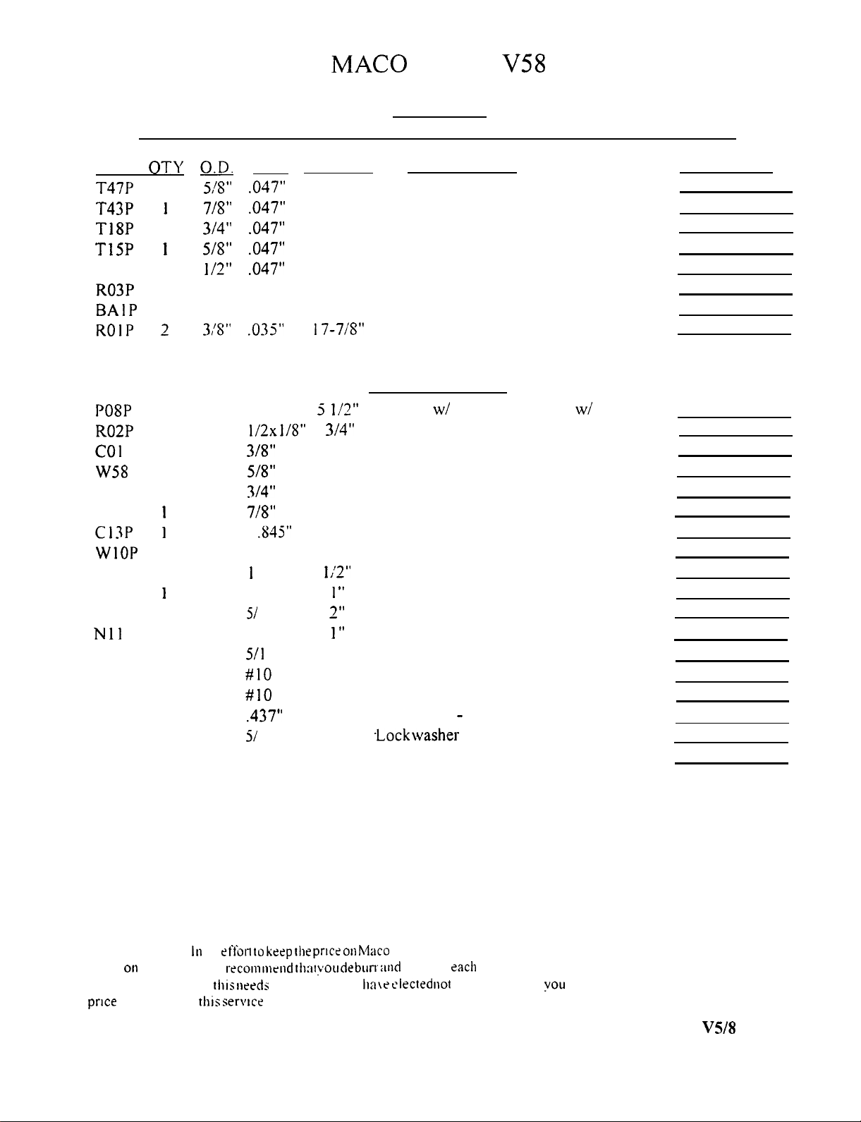
MAC0
ALPHA
V58
26
-
33 MHZ Base Station Antenna
ASSEMBLY INSTRUCTION
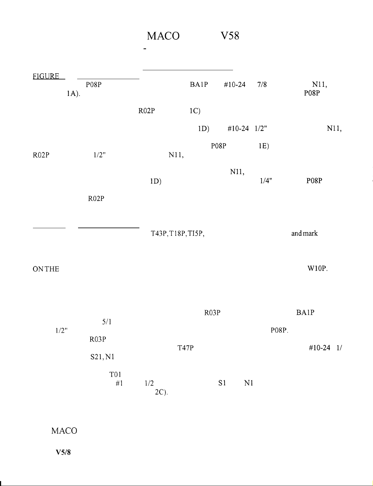
FlGURE
1
BASE ASSEMBLY
Install the
PO8P
Bracket to the base assembly
BAlP
with
#lo-24
x 1
7/8
hardware S45,
Nil,
N12
(ref. Detail
1A).
It should make a 90 degree angle with the base assembly. If not, bend the
PO8P
until it
does.
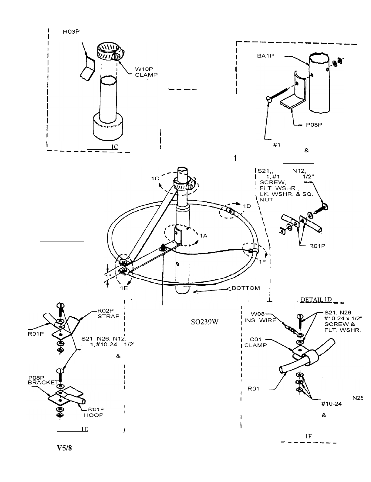
Fasten one end of the strap
R02P
(ref. Detail
1C)
to the vertical end of the base section using the
stainless steel worm drive clamp supplied. Tighten snugly but not too tight as this may have to be adjusted.
Next join the two hoop rings together (ref. Detail
1D)
using
#lo-24
x
l/2”
hardware S21, N26,
Nil,
N12.
Now fasten one end of the hoop ring RO 1 P to bracket
PO8P
(ref. Detail
1E)
and the other end to strap
R02P
using IO-24 x
l/2”
hardware S21, N26,
Nil,
N12.
Position the aluminum clamp CO 1 on the hoop ring assembly approximately where shown (ref. Detail
1 F) and attach the wire as shown using # 1 O-24 hardware S 11, N26,
Nl
1,
N12; do not tighten. Now measure
from the center of the screw (ref. Detail
1D)
around the outside of the ring 6 l/4” toward the
PO8P
end of
the hoop ring assembly until the edge of the clamp CO 1 is against the mark; tighten snugly. Now make the
final adjustment of R02P so that the distance between the ends of the rings is 1”. This is a vertical separation
of 1”. (Ignore the screws in this measurement) and tighten the clamp firmly.
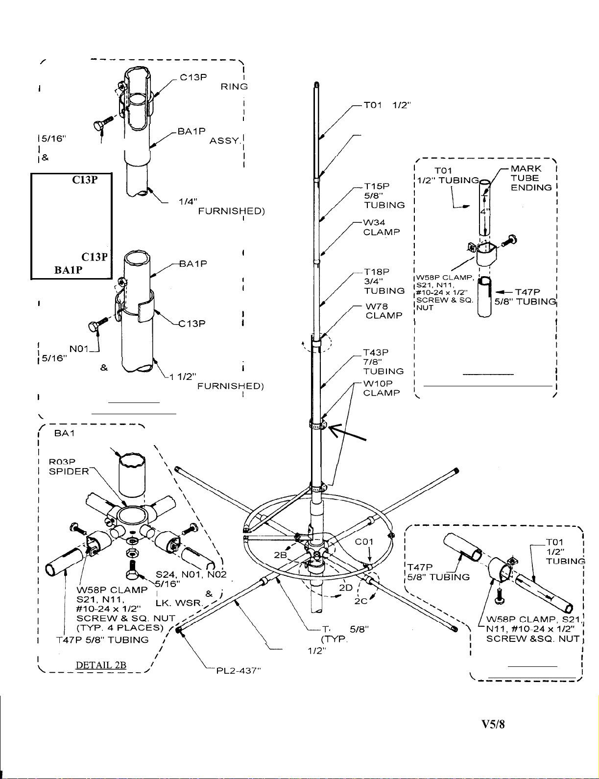
FIGURE 2 BASE ASSEMBLY
To install the vertical elements, # T43P, T18P, TISP, use a felt tip marker and ruler,
andmark
6” from
the unslotted end. Mark the TO 1 P 4” from one end. Now using the clamps and hardware as shown (ref. Detail
2A) slide the unslotted ends into the larger sections to the mark and tighten clamps. Install the plastic cap
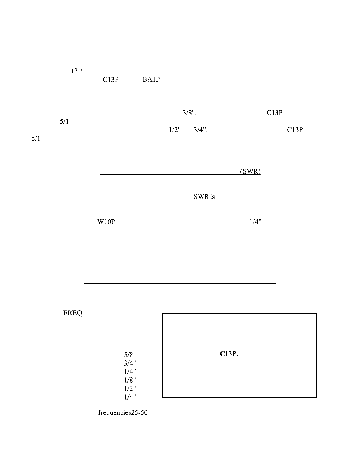
PL2 on the top. THE OVERALL LENGTH MUST BE SELECTED FROM THE FREQUENCY CHART
ONTHE NEXT PAGE AND ADJUSTED TO THIS MEASUREMENT. Shorten at top Clamp
WlOP.
This
is important to assure low SWR; however, the chart length is not sacred and may be changed to allow for
objects close enough to the antenna to cause the SWR to be affected. For frequencies falling between those
shown on the chart, it is suggested that interpolation be used to get the starting point for adjusting. Note:
The bottom means the very bottom!
To install the radials, first put the aluminum bracket R03P spider on the base section
BAlP
as shown
in Detail 2B. Install the 5/l 6 x 1 hex bolt,, nut, and washer in the bracket. The bracket is positioned so that
there is
l/2”
clearance between the top of the spider and the bottom of the bracket
PO8P.
This position puts
the top edge of the
R03P
spider just where the base section stops tapering and gets back to full size. Now
tighten the bolt and lock nut. Next take the four
T47P
radials and the four clamps W58 with
#lo-24
x
l/
2 screws, hardware
S21,
Nl
1; and place the clamps with hardware installed over the end of the tubing up
on a bracket stub and tighten. Now repeat with the other three radials.
Next take the four
TO1
P radials and using a marking pen, mark 4” from the end on all four radials.
Now using clamps W58 and
#l
O-24 x
l/2
screws with hardware
Sl
1 and
Nl
1; insert the marked end to the
mark and tighten the clamps (ref. Detail
2C).
Install the four Black
Plastic Caps PL2 on the ends. Exact length is not critical.
MAC0
MANUFACTURING, 4091 VISCOUNTAVE., MEMPHIS, TN 38118
For parts or information call (901) 794-9494.
V5/8
2