manuals.online logo
Brands
  1. Home
  2. •
  3. Brands
  4. •
  5. Mad Bean Pedals
  6. •
  7. Music Pedal
  8. •
  9. Mad Bean Pedals VFE Switching Board User manual

Mad Bean Pedals VFE Switching Board User manual

VFE Switching Board
© 2017 madbeanpedals
Some images © 2017 VFE Pedals, used with permission
8.7 update: see pg. 7
2.16” W x 1.33” H
2
The VFE Switching Board and micro-controller are included with all the VFE projects available from madbeanpedals.
This switching scheme employs “soft bypass”, meaning a momentary non-latching SPST foot-switch is used in place of
the ubiquitous 3PDT. This offers some advantages:
 SPST momentary switches and relays generally have much lower failure rate than the 3PDT.
 It’s easier to actuate than a latching bypass.
 Nearly silent operation (no more “pops!”).
 Secondary “momentary” function.
The switching scheme utilizes a pre-programmed micro-controller to actuate a DPDT relay. This relay handles I/O
functions for the (separate) audio effects boards. Therefore, the Switching Board must be wired to an audio board to
complete the bypass switching for the effects.
VFE has also gotten very clever; in addition to the components necessary to operate the switching, other circuitry is
included. These are power filtering for DC supply, an optional charge pump (since many of the VFE effects use a split-rail
power supply), effect input and output pull-down resistors as well as on-board DC and I/O jacks. This greatly simplifies the
design of the individual audio boards in each project since the common portions to all audio effects are handled by the
Switching Board.
The Switching Board is held in place with board mounted audio jacks. The momentary switch is attached via two wires
and is not directly mounted to the Switching Board. This means you will need precision when drilling your enclosure to
ensure the jacks fit properly and the DC Jack clears its drill hole. Fortunately, Peter has been kind enough to make a
demonstration video to show you how to build these projects to the VFE standard!
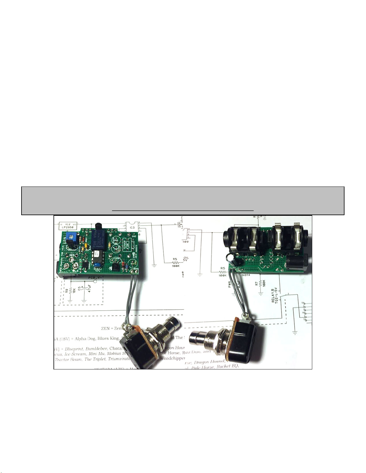
A completed Switch Board (without voltage inverter)
The Switching Board pictured above was built for the Alpha Dog which does not use split-rail power. Therefore, the 7662
inverter chip and associated caps were left off. As you can see, most components are top mounted on the board with the
exception of the 150uF power decoupler which is mounted on the bottom. Note that the micro-controller does not use a
socket. This is to prevent the chip from becoming too tall and interfering with the enclosure lid. Similarly, Peter
recommends you fold all the transistors down a bit before attaching the lid to prevent damage. This build does not use the
spec’d audio jacks (more on that later).
How to finish a VFE Pedal build - Peter Rutter
https://www.youtube.com/watch?v=vAvK-yB_29M
3
I Give You Infinite Powers
The DC Jack inserts into DC9V. Note that the sleeve and tip are flipped since we commonly use center-tip negative power
supplies. Power is reverse-polarity protected via D1. It then passes through a 1mH inductor which creates a low pass filter
with the C1 decoupler. This helps reduce noise and minimize ripple on the DC power (additional 100n decoupling caps
are used on the audio boards). A Zener diode is included to prevent over-voltage to both the audio PCB and the 7662
inverter (when used). Its value depends on which audio circuit is being built.
The power splits in two different directions: one goes to the audio board (via PCB_V+) and the second to the 5v regulator
(IC2). This regulator powers the micro-controller, which in turn activates the coil on the relay. It is decoupled with a 4u7
MLCC.
Do You Like My Parts?
For audio effects that use a split-rail design, a 7662 is used as an inverter (red area). Here the filtered DC is connected to
the 7662 at pin8. Pin1 is shorted to pin8 to utilize the on-board frequency booster. This keeps the internal oscillator of the
7662 out of the audio range. Pin5 outputs a negative voltage (-9v) and is decoupled with a 47uF cap (C3). It supplies the
audio PCB via PCB_V-. The second 47uF cap (C2) is used to charge up the voltage inversion within the 7662.
The blue area is an exception used only in the Choral Reef. It supplies a bias voltage to certain parts of that circuit design.
C5 is not actually a separate cap on the Switching Board. Rather, it is the same cap as C3, but installed in reverse (“+”
side to PCB_V- and "–" side to ground). Again, this is only with the Choral Reef.
4
Controllers, Coils and Things
The 5v tap connects to the micro-controller (IC3: PIC12F509) for power. The relay coil (TQ2-L-5v) connects to pins 3 and
6 on the PIC. Pin4 of the PIC connects to ground via a 1k resistor and momentary switch. When the momentary switch is
depressed, the PIC “reads” that input and sends a voltage pulse to the relay to activate the coil. This causes the internal
DPDT of the relay to flip states (between bypass and effect in our case).
A couple other things happen at the same time when the switching engages.
Pin7 of the PIC is 0v in effect mode, 5v in bypass mode.
1) When the relay is in bypass-mode, pin7 of the PIC puts out a continuous 5v which is applied to the gate of Q1.
This grounds the power rail created by R6 to turn off the bypass LED by using the mosfet as a switch. IOW, the
nominal state for the LED is on and the mosfet “interrupts” (grounds) the power to the LED on bypass. The 20k
trimmer is for the user to control their preferred LED brightness.
2) Q2 is used as a variable resistor. In effect-mode, pin7 grounds the gate of Q2 and the resistance between the
drain and source is on the order of 120 Ohm. This acts as a small series resistance for the audio output and R7
behaves as output pull-down. From there, the audio output goes to the output jack.
3) In bypass mode, pin7 switches to 5v and the resistance between drain and source on Q2 goes to its nominal
value (infinite for argument’s sake). This mutes the PCB_OUT signal as the DPDT switches back to bypass-mode
to prevent any noise from going to the output jack. When it goes back to effect mode, the 100k resistor (R5)
grounds and the 100n cap begins to discharge. The slower discharge from the 100k/100n time constant may help
create more consistent on/off action in the momentary mode (my guess).
Note
- The schematic lists TQ2-L-5v as the relay in this schematic, but VFE used the TQ2-L-4.5v as well. According to
Peter both work fine but he tended to use the 4.5v relay. The 5v is listed in the Mouser BOM because it is more
regularly stocked.
- The J175 is a P-channel JFET, but is drawn here as an N-Channel. P-Channel must be used here for correct
operation.
5
Whar Signal Goes? Whar??!!!
You can see from this snippet that the Switching Board utilizes an effect-input grounding scheme. IOW, when the audio
circuit is bypassed its input is grounded.
So Good, You Bought It Twice
The Switching Board has one other feature: a secondary momentary mode. In this mode, the switching behaves like a
momentary on/off rather than a latching switch. Don’t worry – it’s still true bypass. In this mode the effect is only on while
you have the foot-switch pressed.
To activate momentary mode, do not press the switch for 5 seconds. Then tap it twice quickly. Now press and hold for a
few seconds until the LED starts to blink. You are not in momentary mode.
To de-activate momentary mode and go back to latching mode, do the same process again. Wait 5 seconds, tap, tap,
hold. If you encounter problems switching back disconnect/reconnect the DC power.
Note
- The schematic lists the jack as NMJ6HCD2-SM. This is a “sleeve make” jack. When the jack is inserted, it lifts
the sleeve to connect to the switched portion of the jack (thus connecting DC ground to the circuit ground). The
schematic labels this pin as “SN” but it should be “SM”.
6
Jacked Up
You should use the jack spec’d in the schematic (linked in the Mouser BOM). It actually doesn’t matter if you use a stereo
or mono jack since the ring portion of the stereo jack is not connected to anything. It does, however, require this particular
“sleeve make” setup to connect DC ground.
A “sleeve make” jack – the sleeve contacts the switched pin to make the DC Ground connection.
If you do not use a sleeve make jack (the “sleeve normal” jack, for instance), then you will need to short the sleeve and
switched pin together as shown below.
Here the sleeve and switched pin are shorted together with a buss wire for DC ground.
One last word about jacks: whether you use the “sleeve make” or “sleeve normal” you must use a Neutrik.
Other jacks have the same pin spacing but slightly different tolerances in their casings and will not fit properly. Again, links
to the proper jacks are in the BOM.
Finally, you might realize at this point that the entire circuit it ground isolated. IOW, there is no chassis grounding point
with the Switching Board or the hardware attached to it (same goes for the audio boards). Therefore, we need to create a
ground path to the chassis.
Peter demonstrates his method in the video linked on pg.2 I suggest you watch the video and see how he does it (using a
small bead of solder on the jack ferrule to ensure sleeve to chassis contact). No issue with doing it that way at all, but here
is an alternative (I find this easier).
Use the ½” lock washer you get with foot-switches (some a serrated, others are link...doesn’t matter) and solder a wire to
it. Solder the other end to the sleeve of the DC Jack. So, when your foot-switch is locked down the washer contacts the
chassis and makes the ground connection. Either method is fine…it’s up to your personal preference
Note
While you can get around using the “sleeve make” jack if you don’t have them, you will not be able to use a battery.
When you wire the sleeve and switched sleeve together, removing the input jack will not disconnect the battery power
and therefore it will drain quickly. But, you shouldn’t be using a battery anyway…they are wasteful and damaging to
the environment unless properly recycled!
7
Lock washer soldered to the DC Jack sleeve.
For convenience, I have created a MOUSER project for the Switching Board components. It includes ALL options, so be
sure to remove the items you don’t need. Note: It does not include the momentary switch.
8.7 update: Mouser appears to no longer stock the low-ESR 47uF caps originally listed. I have replaced those in
the project link with 10uF and 22uF low-profile/low ESR caps. You can use either one (qty 2) depending on what
is in stock.
Momentary Switch
VFE uses this switch in their pedals:
http://smallbear-electronics.mybigcommerce.com/110-pm-off/
- These are more expensive, but are very rugged. They are momentary but provide a “click” when pressed.
Regular soft touch momentary are less expensive and will work fine:
http://smallbear-electronics.mybigcommerce.com/momentary-spst-no-soft-touch/
If you want to go really cheap, I have also tested these and they seem to work okay:
http://bitcheslovemyswitches.com/#!/SPST-Soft-Touch-Momentary-Footswitch-Normally-
Open/p/10220659/category=5027572
I do not have the code to program the micro-controllers. This is proprietary to VFE.
Mouser Project: VFE_SwitchingBoard
http://www.mouser.com/ProjectManager/ProjectDetail.aspx?AccessID=b1a505584d
TIP: If you’d like to learn more about soft-bypass switching, check out these terrific tutorials available at Code Effects
http://www.coda-effects.com/2016/04/relay-bypass-conception-and-relay.html
http://www.coda-effects.com/2017/02/relay-bypass-final-code.html
8
Type QTY Desc. Rating Used With
1k 1 Metal Film 1/2W ALL
1k 1 Metal Film 1//8W ALL
8k2 1 Metal Film 1//8W Choral Reef only
10k 1 Metal Film 1//8W Choral Reef only
100k 2 Metal Film 1//8W ALL
10M 1 Metal or Carbon Film 1//8W ALL
100n 1 MLCC 25v min ALL
4u7 1 MLCC 16v min ALL
47uF 2 Low ESR Electrolytic 16v min Split Rail, Choral Reef
150uF 1 Electrolytic 25v min ALL
BS170 1 ALL
J175 1 ALL
Inductor 1 Axial, 1mH ALL
1N5817 1 ALL
Zener 1 *see chart ALL
Relay 1 TQ2-L-4.5v/5v ALL
LP2950 1 5v Regulator ALL
TC7662B 1 Voltage Inverter Split Rail only
Audio Jacks 2 NMJ6HCD2-SM ALL
DC Jack 1 Kobiconn PC Mount ALL
20k 1 Bourns 3362P trimmer ALL
Switch 1 Momentary SPST ALL
B.O.M.
18v
16v
13v
Blueprint, Bumblebee, Choral
Reef, Dark Horse, Fiery Red
Horse, Focus, Mobius Strip, Old
School, Pale Horse,
Springboard, The Triplet,
Triumvirate, White Horse
Merman
Alpha Dog, Blues King,
Distortion3, The Scream
Zener Chart
Split Rail Projects
Blueprint, Bumblebee, Dark Horse, Focus,
Mobius Strip, Pale Horse, Springboard, The
Triplet, Triumvirate, White Horse
Additional notes from Peter:
- The outer two legs of the J175 can be jumped for standard true bypass operation (instead of TrueSoft)
- R6 can be 1/8W if using a power supply is 11V or less, or 1/4W if power supply is 15V or less. The 1/2W
rating was put there in case an 18V power supply was used.
9
Switching Board Schematic

Other Mad Bean Pedals Music Pedal manuals

Mad Bean Pedals Tapanatorator User manual

Mad Bean Pedals

Mad Bean Pedals Tapanatorator User manual

Mad Bean Pedals Rabbit Hole User manual

Mad Bean Pedals

Mad Bean Pedals Rabbit Hole User manual

Mad Bean Pedals Mangler User manual

Mad Bean Pedals

Mad Bean Pedals Mangler User manual

Mad Bean Pedals Afterlife 2020 User manual

Mad Bean Pedals

Mad Bean Pedals Afterlife 2020 User manual

Mad Bean Pedals AQB_MOD 2019 User manual

Mad Bean Pedals

Mad Bean Pedals AQB_MOD 2019 User manual

Mad Bean Pedals Bumblebee User manual

Mad Bean Pedals

Mad Bean Pedals Bumblebee User manual

Mad Bean Pedals Aquaboy Deluxe User manual

Mad Bean Pedals

Mad Bean Pedals Aquaboy Deluxe User manual

Mad Bean Pedals Wavelord User manual

Mad Bean Pedals

Mad Bean Pedals Wavelord User manual

Mad Bean Pedals Edgelord User manual

Mad Bean Pedals

Mad Bean Pedals Edgelord User manual

Mad Bean Pedals TONEBENDER User manual

Mad Bean Pedals

Mad Bean Pedals TONEBENDER User manual

Mad Bean Pedals Harbinger Two User manual

Mad Bean Pedals

Mad Bean Pedals Harbinger Two User manual

Mad Bean Pedals 8-Ball User manual

Mad Bean Pedals

Mad Bean Pedals 8-Ball User manual

Mad Bean Pedals Green Bean User manual

Mad Bean Pedals

Mad Bean Pedals Green Bean User manual

Mad Bean Pedals DEADRINGER JR. User manual

Mad Bean Pedals

Mad Bean Pedals DEADRINGER JR. User manual

Mad Bean Pedals VFE Switching Board V.2 User manual

Mad Bean Pedals

Mad Bean Pedals VFE Switching Board V.2 User manual

Mad Bean Pedals Woodstock User manual

Mad Bean Pedals

Mad Bean Pedals Woodstock User manual

Mad Bean Pedals Zygote User manual

Mad Bean Pedals

Mad Bean Pedals Zygote User manual

Mad Bean Pedals Aquaboy Deluxe 2019 User manual

Mad Bean Pedals

Mad Bean Pedals Aquaboy Deluxe 2019 User manual

Mad Bean Pedals Road Rage User manual

Mad Bean Pedals

Mad Bean Pedals Road Rage User manual

Mad Bean Pedals RabbitHole2020 User manual

Mad Bean Pedals

Mad Bean Pedals RabbitHole2020 User manual

Mad Bean Pedals Pastyface User manual

Mad Bean Pedals

Mad Bean Pedals Pastyface User manual

Mad Bean Pedals Bumblebee User manual

Mad Bean Pedals

Mad Bean Pedals Bumblebee User manual

Mad Bean Pedals Retrograde 2019 User manual

Mad Bean Pedals

Mad Bean Pedals Retrograde 2019 User manual

Mad Bean Pedals HoneyDripper User manual

Mad Bean Pedals

Mad Bean Pedals HoneyDripper User manual

Popular Music Pedal manuals by other brands

AJH Synth MiniMoD VCO user guide

AJH Synth

AJH Synth MiniMoD VCO user guide

Behringer TUBE AMP MODELER TM300 manual

Behringer

Behringer TUBE AMP MODELER TM300 manual

FEA OPTI-FET user manual

FEA

FEA OPTI-FET user manual

Chase Bliss Audio Cooper FX Generation Loss instructions

Chase Bliss Audio

Chase Bliss Audio Cooper FX Generation Loss instructions

BOSSCO GP-20 owner's manual

BOSSCO

BOSSCO GP-20 owner's manual

Source Audio Soundblox 2 user guide

Source Audio

Source Audio Soundblox 2 user guide

GR BASS Dual PRE user manual

GR BASS

GR BASS Dual PRE user manual

digi-tech Element quick start guide

digi-tech

digi-tech Element quick start guide

BOSSCO DSP-3 Digital sampler/delay instructions

BOSSCO

BOSSCO DSP-3 Digital sampler/delay instructions

One Control Persian Green Screamer user manual

One Control

One Control Persian Green Screamer user manual

BOSSCO SYB-3 owner's manual

BOSSCO

BOSSCO SYB-3 owner's manual

tech21 SansAmp Character Series owner's manual

tech21

tech21 SansAmp Character Series owner's manual

tech21 VT Bass Specifications

tech21

tech21 VT Bass Specifications

BOSSCO ME-20 Turbostart

BOSSCO

BOSSCO ME-20 Turbostart

digi-tech GSP 21 Legend owner's manual

digi-tech

digi-tech GSP 21 Legend owner's manual

BOSSCO ME-90 quick start guide

BOSSCO

BOSSCO ME-90 quick start guide

BOSSCO CE-5 instructions

BOSSCO

BOSSCO CE-5 instructions

BOSSCO LMB-3 owner's manual

BOSSCO

BOSSCO LMB-3 owner's manual

manuals.online logo
manuals.online logoBrands
  • About & Mission
  • Contact us
  • Privacy Policy
  • Terms and Conditions

Copyright 2025 Manuals.Online. All Rights Reserved.