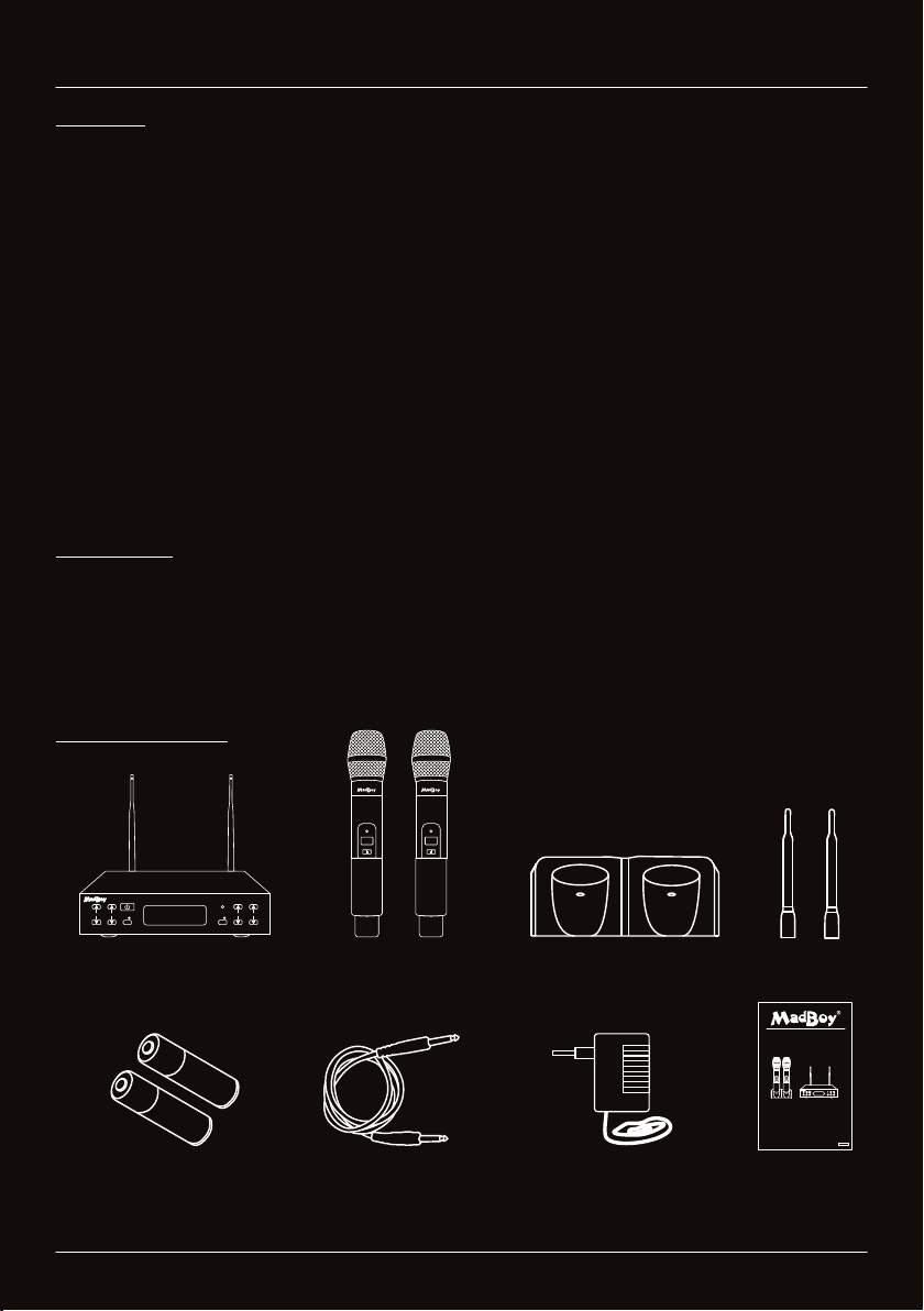
WWW.MADBOY-AUDIO.COM
Wireless Microphone
8
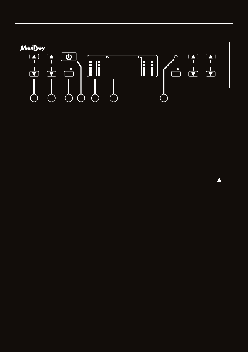
Functions
1. GRILL: Removable metal grill protects a cartridge from damage and an inner foam filter
reduces wind, breath and pop noises.
2. IR: IR receiver for setting the frequency of the microphone. Align this point towards the
receiver during sync.
3. DISPLAY: Display indicates currently used frequency and battery level. If the battery level
indicator is blinking, it means the battery level is low. Low battery level may cause
dropouts or completely signal loss. Please charge the batteries immediately.
4. POWER BUTTON: Keep the button pressed a moment to turn the microphone on or off.
5. BATTERY COVER: Battery compartment for two rechargeable ’AA’ batteries. Remove
batteries if the microphone is not used for long time.
6. CHARGING CONTACTS: Charging contacts on the bottom of the wireless microphone.
Do not charge non-chargeable batteries!
Operation
1. Open the battery cover by turning the cover counterclockwise. Install two rechargeable
’AA’ batteries and close the cover. Pay attention to the correct polarity.
2. Turn on the microphone by keeping the power button pressed awhile. Currently used
frequency is shown on the display.
3. Check that the microphone’s and receiver’s frequencies are same. If the frequency
doesn’t match, send the frequency by shortly pressing the SET button on the receiver
and align the microphone towards the receiver.
4. Receiver’s RF level indicator should turn on now to indicate connection between the
wireless microphone and the receiver.
5. Turn off the microphone by keeping the power button pressed awhile.
Please handle the wireless microphone with care.
Warranty does not cover damage caused by accidental
misuse of the product.
Notice:
ŸReceiver’s channel A have frequency channels of 0-16 and channel B have frequency channels
of 17-33. Microphones are not limited to work only at channel A or B, so both microphones can
be set to channel 0 to 33.
ŸMake sure that both microphones are not set at same frequency channel. This will cause signal
degration and complete signal loss.
ŸThe microphone frequency is always changed by pressing SET button on the receiver. You
cannot change the frequency from microphone.