manuals.online logo
Brands
  1. Home
  2. •
  3. Brands
  4. •
  5. MADDALENA
  6. •
  7. Accessories
  8. •
  9. MADDALENA KUS User manual

MADDALENA KUS User manual

1
Installation instructions
KUS ultrasonic flow sensor
1General information
1.1 Use
The instrument described in this manual is a flow sensor designed
for use with a calculator for determining the consumption of
thermal energy in heating or cooling systems that use water.
The flow meter consists of a metal measuring part combined with
a calculator. These two components are connected by a cable.
1.2 General notes
The flow meter left the factory in a faultless condition where safety
is concerned. The manufacturer will provide additional technical
support on request. Calibration relevant security seal on the flow
meter must not be damaged or removed. Otherwise the guarantee
and calibration validity of the flow meter will lapse.
Keep the packaging so that you can transport the flow meter in
its original packaging following expiry of the calibration validity.
Lay all cables at a minimum distance of 500 mm to high voltage
and high frequency cables.
A relative humidity of < 93 % at 25 °C is permissible (without
condensation).
Avoid cavitation in the whole system due to overpressure i.e. at
least 1 bar at qp and approx. 3 bar at qs (applies for approx.
80 °C).
2Safety information
The flow meter may only be used in building service
engineering systems and only for the applications
described.
The local regulations (installation etc.) must be adhered
to.
Adhere to the operating conditions according to the dial
plate during use. Non-adherence can cause hazards and
the guarantee will lapse.
The flow meter is only suitable for circulating water in
heating systems.
The flow meter is not suitable for drinking water.
Adhere to the AGFW requirements regarding circulating
water (FW510).
Do not lift the flow meter by the calculator.
Be aware of sharp points on the thread, flange and
measuring tube.
Only personnel, trained in the installation and operation
of meters in heating and cooling systems, may install and
remove the flow meter.
Only install or remove the flow meter when the pipes are
pressure-less.
After installing the flow meter, check the leak-tightness
of the system.
Guarantee and calibration validity will lapse if the
calibration relevant security seals are broken.
Only clean the flow meter from outside with a soft,
lightly wetted cloth. Do not use any spirit or cleaning
solvent.
As far as disposal is concerned, the flow meter is a waste
electronic appliance in the sense of European Directive
2012/19/EU (WEEE) and it must not be disposed of as
domestic waste. The relevant national, legal regulations
must be observed as the appliance must be disposed of
via the channels provided for this purpose. The local and
currently valid legislation must be observed.
The meter contains lithium batteries. Do not dispose of
the meter and the batteries with domestic waste.
Observe the local stipulations and laws on disposal.
You can return the lithium batteries to the manufacturer
for appropriate disposal following use. When shipping
please observes legal regulations, in particular, those
governing the labelling and packaging of hazardous
goods.
Do not open the batteries. Do not bring batteries into
contact with water or expose to temperatures above
80 °C.
The flow meter does not have any lightning protection.
Ensure lightning protection via the in-house installation.
3Installation
Proceed as follows to install the flow meter:
Observe the dimensions of the flow meter and check whether
there is sufficient space available.
Rinse the system thoroughly before installing the flow meter.
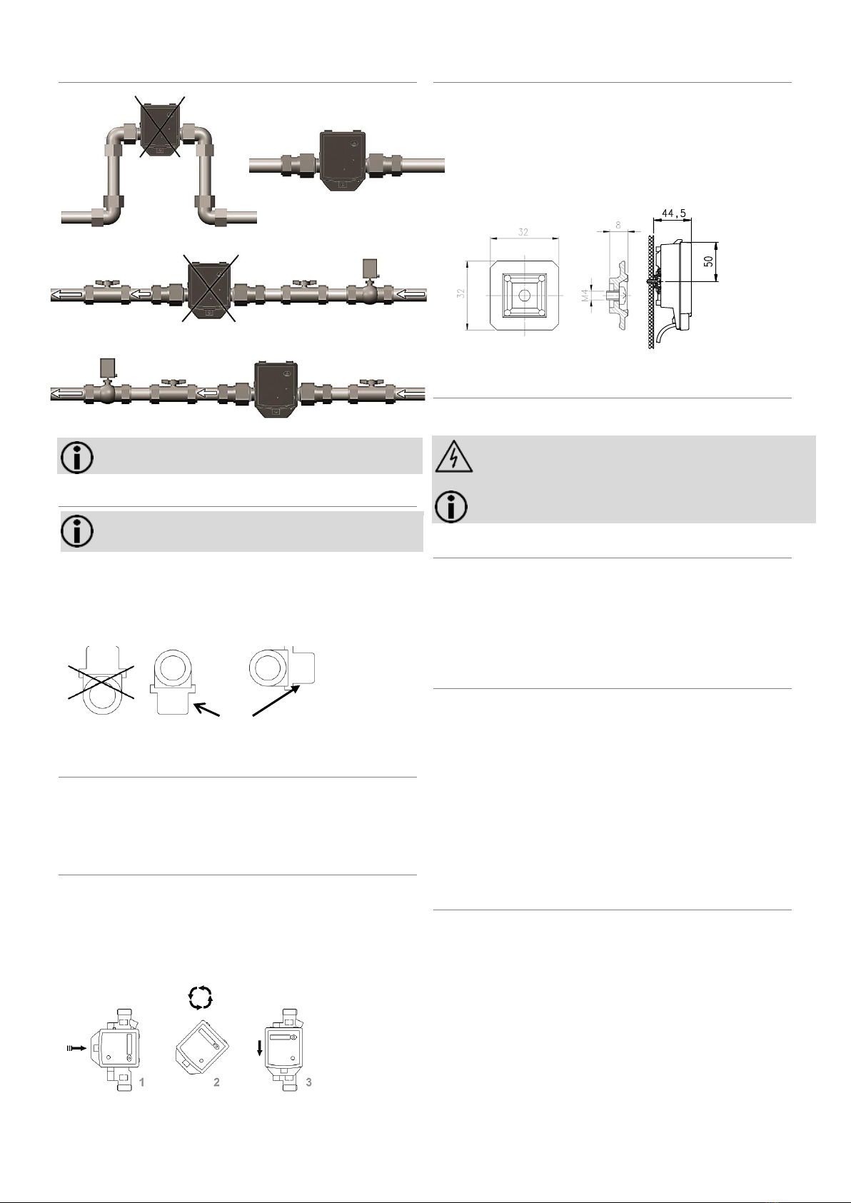
Fit the flow meter vertically or horizontally between two slide
valves so that the arrow on the housing and the flow direction
match. Also observe the installation situations and the
following examples of installation (see figure 2 and figure 3).
Loosen the elastic band or the cable tie, provided for the
transport, from the volume measurement unit. In operation,
the control cable should not depend directly on the volume
measurement unit.
If you install the flow meter for cold metering, follow the
appropriate instructions.
Recommendation: If you are installing more flow meters in one
unit, make sure that all the flow meters operate under the same
mounting conditions.
3.1 Installation notes
Note: When installing the flow meter the locally
applicable installation regulation for flow meters must be
observed.
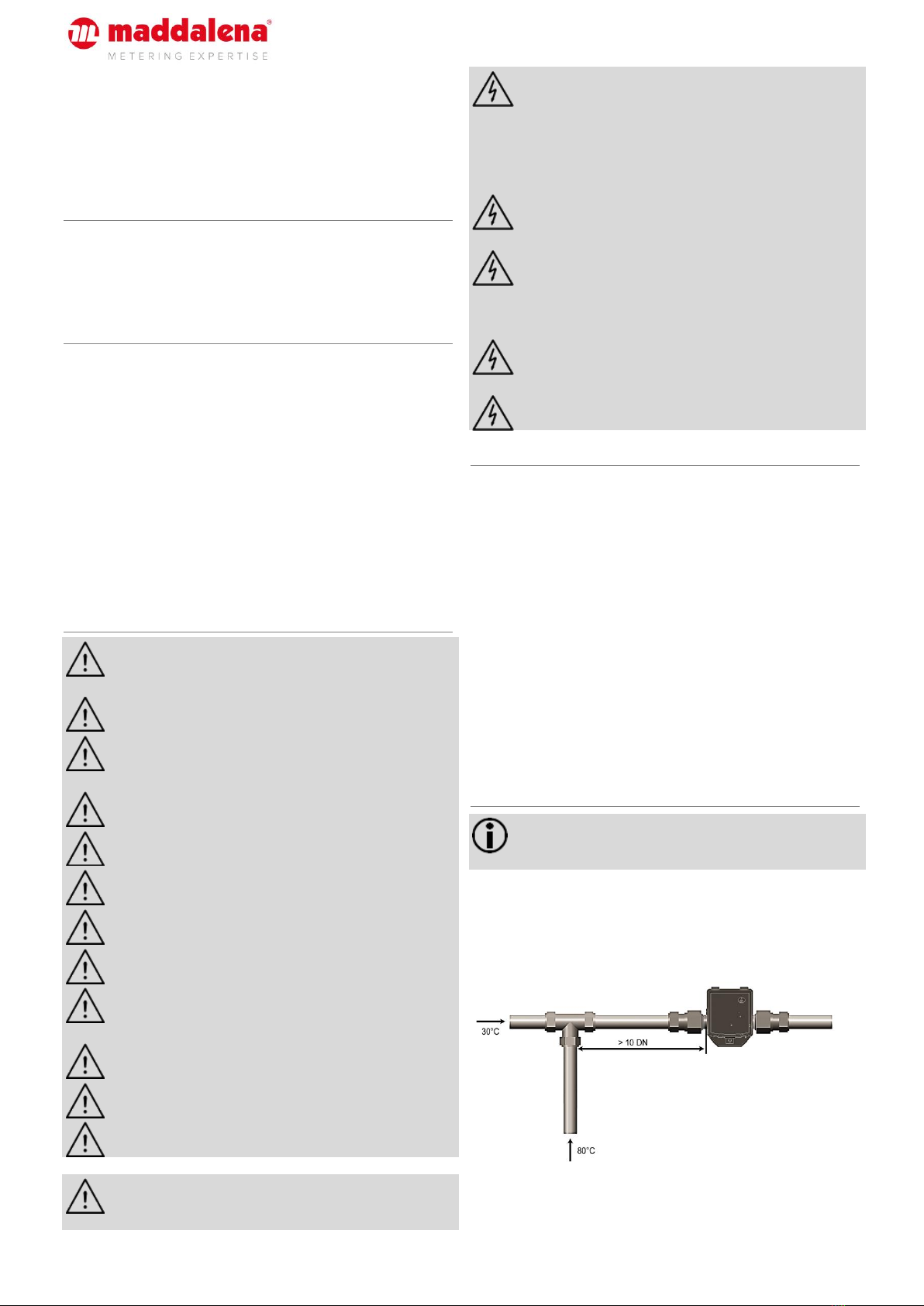
Upstream and downstream straight pipes are not necessary. If you
install the flow meter in the common return of two circuits,
determine a place of installation with a minimum distance of
10 × DN from the T-piece. This distance ensures a good thorough
mixing of the different water temperatures.
Fig. 1: Mixture of different return temperatures
0 01/19
|
Subject
to
technica
l change
2
3.2 Examples of installation
Fig. 2: Avoid accumulation of air
Fig. 3: Mount a valve or a regulator after the flow meter
Note: During installation it must be ensured that no water
can enter the calculator.
3.3 Installation for cooling metering
Note: It is recommended that the flow meter is installed
on the hot side.
When installing as a cold meter it is essential that the black cover
on the measuring tube is pointed to the side or downwards in order
to avoid problems with condensation forming.
Fit the calculator separate to the volume measurement tube, e.g.
on the wall. Make a loop downwards in order to prevent
condensation running along the connected lines into the calculator.
Transducer cover
Fig. 4: Recommended installation position for cooling metering
4Calculator
The ambient temperature of the calculator must not exceed 55 °C.
Avoid direct sunlight. For water temperatures between 10 °C and
90 °C you can fit the calculator on the volume measurement unit or
on the wall.
4.1 Aligning the calculator
Proceed as follows to align the calculator:
1. Pull the calculator off the volume measurement unit.
2. Turn the calculator to the left or right through 90° or 180° as
required.
3. Push the calculator onto the adapter plate in this position until
it engages.
Fig. 5: Calculator installation position
4.2 Wall fitting (split fitting)
Fit the calculator to the wall at water temperatures below 10 °C
and above 90 °C.
For wall mounting proceed as follows:
Pull the calculator off the adapter plate.
Unscrew the adapter plate from the volume measurement unit.
Fit the adapter plate to the wall.
Push the calculator onto the adapter plate.
Fig. 6: Adapter plate and wall fitting
5Power supply
The flow meter is equipped with a long life battery for ten years of
operation. You can take the operating time from the dial plate.
Warning: Do not open the batteries. Do not bring battery into
contact with water or expose to temperatures above 80 °C.
Dispose of used batteries at suitable collection points.
Note: Only batteries approved by the manufacturer may be
installed.
6Interfaces
The flow meter is equipped with an optical interface in accordance
with EN 62056-21 as standard.
In addition, the flow meter is equipped with a pulse output and is
delivered with a 2m two wire cable. The connecting cable can be
lengthened with a cable 2 x 0.75 mm2. A distributing box is
recommended.
7Activation of the calculator
For activation proceed as follows:
Open the slide valves slowly.
Check the system for leak-tightness and bleed air out carefully.
After more than 100 sec. the flow meter begins to work.
If the operating limit is exceeded and the flow rate is positive,
volume pulses are generated according to the pulse parameter
settings.
Check the measured value flow or the volume of progress on
the connected calculator for plausibility.
Vent the system until the flow rate value on the calculator is
stable. Check the output.
8Functional details
The operating hours are counted from the first connection of the
power supply.
Missing hours are summated if there is an error and the flow meter
is thus unable to take a measurement.
Volume readings, maximum flow rates and missing hours are
stored monthly for 36 months.
The device number and the firmware version number are issued by
the manufacturer.
3
9Technical data
Note: The information on the flow meter must be
observed!
General information
Measuring accuracy
Class 2 (EN 1434)
Environment class
A (EN 1434) for indoor installation
Mechanical class
M1 (according to Directive 2014/32/EU)
Electromagnetic class
E1 (according to Directive 2014/32/EU)
Ambient humidity
<93% rel. humidity at 25 °C, without
condensation
Max. height
2000 m above sea level
Storage temperature
-20 °C … +60 °C
Calculator
Ambient temperature
+5 °C… +55 °C
Housing protection rating
IP65 according to EN 60529
Power supply
Battery, service life 10 years
Optical interface
Standard, EN 62056-21
Communication
Pulse output
Separability
Always
Pulse output
Type
Open drain
Dielectric strength
500 Veff against ground, galvanic isolation
Pulse options
Depending on the size (refer to the data
sheet)
Pulse length
Maddalena standard 25 ms
Pulse sequence
In packages every 0.5 s (not regular)
Cable length
2 m
Voltage
Maximum 30 V
Current
Maximum 30 mA
Voltage drop
< 0.3 V at 10 mA
Polarity
Bipolar
Volume measurement unit
Protection class
IP65 according to EN 60529
Mounting place
Hot side/cold side (standard: cold side)
Installation position
Any
Straight pipes
Not required
Measuring range
1:100 or 1:50
Recommended
temperature range
+5 °C … +130 °C
National type approvals may vary.
Temperature range for
heat application
+10 °C … +130 °C
Temperature range for
cooling application
+5 °C… +50 °C
Maximum overload
2.8 x qp
Nominal pressure
PN 25 (PS 25)
10 Manufacturer
Landis+Gyr GmbH
Humboldtstrasse 64
90459 Nuremberg
Germany
11 Contacts
Maddalena S.p.A.
Via G.B. Maddalena, 2/4
33040 Povoletto (UD)
Italy
Tel. +39 0432 634811
www.maddalena.it
1 05/19 | Subject to technical change
4
12 Declaration of conformity

Popular Accessories manuals by other brands

multicomp MC011333 manual

multicomp

multicomp MC011333 manual

esera DS18S20 user guide

esera

esera DS18S20 user guide

Rotronic CF8-W-Disp-CO installation manual

Rotronic

Rotronic CF8-W-Disp-CO installation manual

Velux KLA S105 manual

Velux

Velux KLA S105 manual

Solight 1L56 instructions

Solight

Solight 1L56 instructions

xtpower MP-S6000 manual

xtpower

xtpower MP-S6000 manual

DOL 26SCR Series Technical user guide

DOL

DOL 26SCR Series Technical user guide

Migali C-02RM instruction manual

Migali

Migali C-02RM instruction manual

Philips sonicare AirFloss Ultra manual

Philips

Philips sonicare AirFloss Ultra manual

Sarabec chimeflash user manual

Sarabec

Sarabec chimeflash user manual

American Standard Acrylux Corner Shower Door H186 Product features

American Standard

American Standard Acrylux Corner Shower Door H186 Product features

Hama LP-10 instructions

Hama

Hama LP-10 instructions

Broan 90 instructions

Broan

Broan 90 instructions

Siemens enlighted SU-5i-USB install guide

Siemens

Siemens enlighted SU-5i-USB install guide

Enabling Devices 9092 user guide

Enabling Devices

Enabling Devices 9092 user guide

UV Innovators NuvaWave NW-UVC-100 Instructions for use

UV Innovators

UV Innovators NuvaWave NW-UVC-100 Instructions for use

Lightolier MR-16 instruction sheet

Lightolier

Lightolier MR-16 instruction sheet

Procool SP640X quick start guide

Procool

Procool SP640X quick start guide

manuals.online logo
manuals.online logoBrands
  • About & Mission
  • Contact us
  • Privacy Policy
  • Terms and Conditions

Copyright 2025 Manuals.Online. All Rights Reserved.