Mafell MKS185Ec Assembly instructions

MKS185Ec
170699 .0122/a
IMPORTANT
Read Before Using
IMPORTANT
Lire avant usage
IMPORTANTE
Leer antes de usar
Operating/Safety Instructions
Consignes d’utilisation/de sécurité
Instrucciones de funcionamiento y seguridad
For English Version
See page 2
Version française
Voir page 27
Versión en español
Ver la página 52

MKS185Ec
2
01/2022
English
Table of contents
1Signs and symbols ........................................................................................................... 3
1.1 Identification of the device................................................................................................5
2Product specifications ......................................................................................................5
2.1 Technical data .................................................................................................................. 5
2.2 Scope of delivery.............................................................................................................. 6
2.3 Adjustment elements........................................................................................................6
3General safety .................................................................................................................. 7
3.1 Intended use..................................................................................................................... 7
3.2 Foreseeable misuse .........................................................................................................7
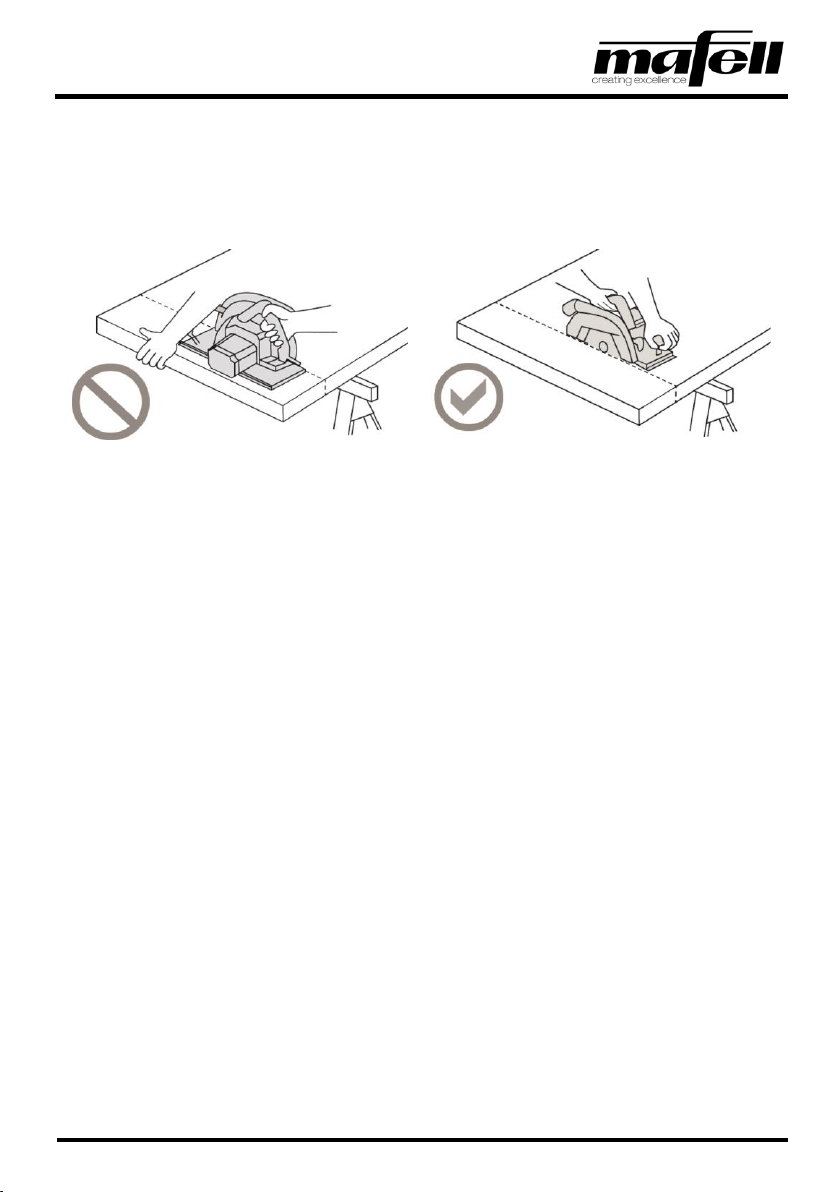
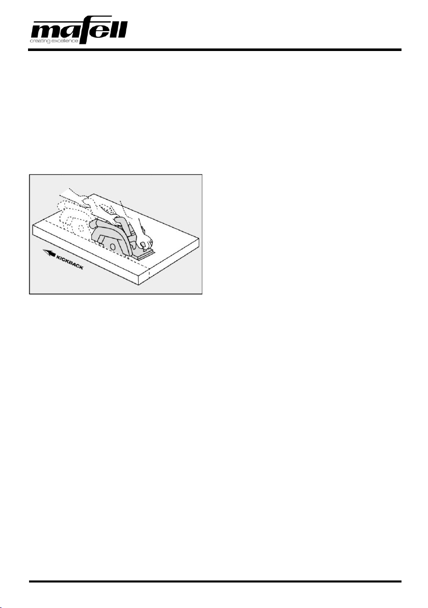
3.3 Safety instructions ............................................................................................................ 8
3.4 Safety devices ................................................................................................................13
3.5 Residual risks ................................................................................................................. 14
4Setup / adjustment .........................................................................................................14
4.1 Mains connection ...........................................................................................................14
4.2 Routing of the connecting cable ..................................................................................... 14
4.3 Chip extraction ............................................................................................................... 15
4.4 Saw blade selection .......................................................................................................15
4.5 Changing the saw blade.................................................................................................16
4.6 Riving knife..................................................................................................................... 18
5Operation........................................................................................................................19
5.1 Startup............................................................................................................................19
5.2 Switching on ...................................................................................................................19
5.3 Rotational speed setting.................................................................................................20
5.4 Switching off ...................................................................................................................20
5.5 Handling at overload ......................................................................................................21
5.6 Cutting depth setting ...................................................................................................... 21
5.7 Setting for bevel cuts......................................................................................................22
5.8 Sawing along markings ..................................................................................................22
5.9 Sawing with the parallel guide fence .............................................................................. 23
6Service and maintenance...............................................................................................23
6.1 Storage........................................................................................................................... 23
7Troubleshooting.............................................................................................................. 24
8Optional accessories ...................................................................................................... 26
9Exploded view and spare parts list................................................................................. 26

MKS185Ec
01/2022
3
1Signs and symbols
These operating instructions contain the following general information signs to guide you, the reader, through
the operating instructions and to provide you with important information.
Sign
Meaning
Important information
This sign highlights user tips and other useful information.
➢
Identifies an intermediate result in a sequence of actions.
✓
Identifies the final result of a sequence of actions.
Tab. 1: General signs and their meanings
Warning icons warn of dangerous points, risks and obstacles.
Icon
Meaning
Warning
This icon can be found at all locations where you can find information regarding your
safety. Non-observance can result in extremely serious injuries.
Warns of danger of electric shock.
Warns of danger caused by dust.
Warns of the danger of cutting.
Warns of the danger of cutting off or severing limbs.
Tab. 2: Warning icons and their meanings

MKS185Ec
4
01/2022
Mandatory icons are intended to prevent accidents.
Icon
Meaning
Wear eye protection.
Wear dust mask.
Wear hearing protection.
Wear protective gloves.
Tab. 3: Mandatory icons and their meanings
During the operation of the power tool there are always actions to be taken where hazards can occur. These
potentially dangerous actions are preceded by warnings which must be observed.
Classification of the danger level (signal words) of warnings
Warning
Meaning and consequences of non-observance
Imminent danger that will cause serious or fatal injuries.
Potentially dangerous situation that can cause serious or
fatal injuries.
Potentially dangerous situation that can cause minor
injuries.
Tab. 4: Structure of warnings

MKS185Ec
01/2022
5
1.1 Identification of the device
The icons listed and explained below can be found on the rating plate or on the product.
Symbol
Explanation
Symbol
Explanation
V
Volt
1, 2, 3, ...
I, II, III, ...
Rotational speed setting
A
Ampere
rpm
Revolutions per minute
Hz
Hertz
ø
Saw blade diameter
W
Watt
~
Alternating current
kg
Kilogram (weight)
Protection class II
min
Minutes (time)
Read operating instructions
s
Seconds (time)
Protective goggles
n0
Rated speed at no load
Hearing protection
n
Rated speed at normal load
Dust mask
2Product specifications
2.1 Technical data
Universal motor
120 V~, 60 Hz
240 V~, 60 Hz
Current at normal load
20 A
15,9 A
Saw blade speed at no load
1400 to 1700 rpm
Saw blade speed at normal load
1300 to 1600 rpm
Cutting depth
105 - 185 mm [4.13 - 7.28 in]
Cutting depth 30°/45°/60°
160/131/93 mm [6.30/5.16/3.66 in]
Saw unit swivel range
0° to 60°
Saw blade diameter max/min
450/413 mm [17.72/16.26 in]
Saw blade body thickness
2.5 mm [0.10 in]
Tool cutting width
4.2 mm [0.17 in]
Saw blade mounting hole
30 mm [1.2 in]
Hose connector diameter
58 mm [2.3 in]
Weight without power cord, without parallel guide fence
15.3 kg [33.73 lbs]
Dimensions (width x length x height)
460 x 720 x 496 mm [18.11 x 28.35 x 19.53 in]

MKS185Ec
6
01/2022
2.2 Scope of delivery
Fig. 1: Scope of delivery
Components
A
Hand-held circular saw
B
Allen key in a holder on the machine
C
Parallel guide fence
2.3 Adjustment elements
Fig. 2: adjustment elements
Adjustment elements on the machine
1
Tilting segment scale
2
Pre-feed lever
3
Rotary handle
4
Cutting depth scale
5
Clamping lever
6
Switch-on lock
7
Wing screws
8
Operating lever
9
Saw blade speed setting wheel
(rear of motor)
10
Locking pin
11
Tilting segment wing screw

MKS185Ec
01/2022
7
3General safety
Please read all safety instructions and directions. Failure to comply with the safety instructions and
directions can cause electric shock, fire and/or serious injuries. Please retain all safety instructions and
directions for future reference.
3.1 Intended use
The hand-held circular saw is only suitable for ripping and cross cutting of solid wood.
Panel material such as chip board, core board and medium density fiber board can also be processed.
Processing wood fiber insulation materials is also possible.
Use only saw blades that are approved by the manufacturer.
3.2 Foreseeable misuse
The machine is not intended for any other use than the intended use listed above.
The manufacturer is not liable for any damage resulting from such other use.
To use the machine as intended, comply with the operating, maintenance and repair conditions specified by
MAFELL.
Foreseeable misuse also includes:
- Tampering with, removing and/or bypassing safety devices of any kind.
- Operating the machine without safety devices.
- Non-observance of safety and warning instructions in the operating instructions.
- Removing the safety and warning labels from the machine.
- Operating the machine by unauthorized persons.
- Failure to follow prescribed maintenance and care instructions.
- Using the machine without a horizontally supported base plate.
- Using the machine for plunge cuts.
Never use:
- Cracked and/or deformed saw blades.
- Saw blades made of high speed steel (HSS saw blades).
- Blunt saw blades as they impose an excessive load on the motor.
- Saw blades with a base body thicker than or a cutting width smaller than the riving knife.
- Saw blades that are not suitable for the no load speed of the saw blade.

MKS185Ec
8
01/2022
3.3 Safety instructions
READ ALL INSTRUCTIONS!
Non-observance of the instructions listed below can cause electric shock, fire and/or serious injuries
.
Work area
- Children and adolescents are not allowed to operate this machine.
- When using the machine outdoors, the use of an earth leakage circuit breaker is recommended.
- Replace damaged cables or plugs immediately. To avoid safety hazards, only MAFELL or an authorized
MAFELL service workshop is allowed to replace parts.
- Prevent sharp kinks of the cable. Do not wrap the cable around the machine, especially when transporting
and storing the machine.
- Do not use this machine when you are tired, or under the influence of drugs, alcohol or medicaments. Be
aware of what you are doing. Stay alert and use common sense.
- Keep children and bystanders at a distance while you are operating the machine. Distractions can cause
you to lose control of the machine.
- Use eye protection, dust mask and hearing protection. Appropriate safety equipment, used
under proper conditions, will reduce the risk of injuries.
Instructions for service and maintenance:
- Cleaning the machine regularly, especially the adjustment elements and the guiding devices, is an important
safety factor.
- Ensure that only genuine MAFELL spare parts and accessories are used. Failure to do so will make
warranty claims and the liability of the manufacturer null and void.
- Prepare a periodic maintenance schedule for your machine. When you clean the machine, be careful
not to disassemble any part of the machine. Reassembling the machine bears the risk that internal
wires are routed incorrectly or pinched, or that return springs of the safety device are mounted
incorrectly. Certain cleaning agents, such as gasoline, carbon tetrachloride, ammonia, etc. can damage
plastic parts.
- Some of the dust produced by sawing, sanding, drilling and other building work contains chemicals
known to cause cancer, birth defects or other reproductive harm. Some examples of these
chemicals are:
- Lead from lead-based paints,
- Crystalline silica from bricks and cement and other masonry products,
- Arsenic and chromium from chemically treated wood.
Your risk from this hazard varies with the frequency at which you perform this type of work. To reduce your
exposure to these chemicals: Work in a well-ventilated area. Work only with approved safety equipment,
such as dust masks that are specially designed to filter out particles of microscopic size.

MKS185Ec
01/2022
9
Specific safety rules
Sawing method
- Keep your hands away from cutting area and saw blade. Hold the auxiliary handle or the motor
housing with your second hand. If both hands hold the saw, they cannot be injured by the saw blade.
Fig. 3: Incorrect sawing vs. correct sawing
- Do not reach underneath the workpiece. Below the workpiece, the guard cannot protect you from the saw
blade.
- Adjust the cutting depth to the thickness of the workpiece. Less than a full tooth height should be
visible below the workpiece.
- Never hold the workpiece in your hands or across your leg while you are cutting it. Secure the
workpiece on a stable support. It is important to secure the workpiece safely. This minimizes the risk of
body contact, jamming of the saw blade or loss of control over the machine.
- Hold the machine by the insulated grip surfaces when you perform work that involves a risk of the
cutting tool hitting hidden power lines or its own power cord. Contact with a live line also energizes the
metallic parts of the machine, causing an electric shock.
- Always use a fence or straight edge guide for ripping. This improves the cutting accuracy and reduces
the possibility of the saw blade jamming.
- Always use saw blades of the correct size and with a suitable arbor hole (e.g. diamond-shaped or
round). Saw blades that do not match the mounting parts of the saw will run out of true, resulting in a loss of
control.
- Never use damaged or wrong saw blade washers or bolts. The saw blade washers and bolts are
designed specifically for your saw, for optimal performance and operational safety.

MKS185Ec
10
01/2022
Kickback - causes and related safety instructions
- Kickback is the sudden reaction resulting from a pinched, jammed, or misaligned saw blade that causes an
uncontrolled saw to lift off and move out of the workpiece toward the operator.
- If the saw blade is pinched or jammed in the closing kerf, it will stall and the motor power will kick the saw
back toward the operator.
- If the saw blade is twisted or misaligned in the saw cut, the teeth of the rear edge of the saw blade can get
pinched in the wood surface, causing the saw blade to move out of the kerf and the saw to jump back
toward the operator.
Fig. 4: Kickback of the machine
Kickback is the result of incorrect or improper use of the saw. It can be prevented by taking appropriate
precautions, as described below.
- Hold the saw firmly with both hands. Position your arms such that you can withstand kickback
forces. Be sure that you are always positioned such that the saw blade is at the side of your body,
never in line with it. In the event of a kickback, the circular saw can jump backward. However, the operator
can take appropriate precautions to control the kickback forces.
- If the saw blade jams or when you stop working, switch off the saw and hold it steady in the material
until the saw blade is stopped. Never try to remove the saw from the workpiece or pull it backwards
as long as the saw blade is moving. This can cause a kickback. Determine and eliminate the cause of
jamming of the saw blade.
- To restart a saw that sits in the workpiece, center the saw blade in the kerf and ensure that the saw
teeth are not jammed in the workpiece. A jammed saw blade can move out of the workpiece or cause a
kickback when the saw is restarted.

MKS185Ec
01/2022
11
- Support large panels to reduce the risk of a kickback from a jammed saw blade. Large panels tend to
sag under their own weight. Panels must be supported on both sides: near the kerf and at the edge.
Fig. 5: Incorrect support vs. correct support
- Never use blunt or damaged saw blades. The kerf produced by a saw blade with blunt or incorrectly
aligned teeth is too narrow, causing increased friction, jamming of the saw blade and kickback.
- Prior to starting sawing, tighten the cutting depth and cutting angle settings. If the settings change
during the sawing process, there is a risk of a jamming saw blade and kickback.
- Be particularly careful when sawing into existing walls or other concealed areas. The saw blade can
jam and cause kickback when cutting into hidden objects.
Function of the lower guard
- Before each use, ensure that the guard is closed properly. Never use the saw if the guard cannot
move freely and does not close instantly. Never clamp or tie the guard. This would leave the saw
blade unprotected. The guard can be bent if the saw drops to the ground. Ensure that the guard moves
freely and does not get in contact with the saw blade or other parts at all cutting angles and cutting depths.
- Check the function of the spring for the lower guard. Have the saw serviced before use if lower
guard and spring do not function properly. Damaged parts, sticky deposits or accumulations of chips
delay the operation of the lower guard.
- Open the lower guard manually only to perform special cuts, such as "plunge cuts" or "compound
cuts". Open the lower guard with the retracting lever. Release the lever as soon as the saw blade
penetrates the workpiece. For all other sawing operations, the lower guard should operate automatically.
- Ensure that the lower guard covers the saw blade when you put the saw down on the workbench or
on the floor. An unprotected coasting saw blade moves the saw against the direction of cut and cuts
whatever is in its way. Be aware of the coasting time of the saw blade.

MKS185Ec
12
01/2022
Function of the riving knife
- Always use the saw blade that is suitable for the riving knife. The riving knife is only effective if the body
of the saw blade is thinner than the riving knife and the tooth width is greater than the thickness of the riving
knife.
- Adjust the riving knife as described in these operating instructions. Incorrect spacing, position and
alignment can be the reason that the riving knife can not prevent kickback efficiently.
- To be effective, the riving knife must be in the kerf. In short cuts, the riving knife is ineffective for
preventing kickback.
- Never operate the saw with a bent riving knife. Even a minor malfunction can slow down the closing of
the guard.
RETAIN THESE INSTRUCTIONS!

MKS185Ec
01/2022
13
3.4 Safety devices
Danger
Risk of injury from missing safety devices
These devices are necessary for the safe operation of the machine. They must
not be removed or rendered ineffective.
➢Check the proper functioning of the safety devices before you start
operating the machine.
➢Never use the machine with missing or ineffective safety devices.
The machine is equipped with the following safety devices:
Safety device
Type of check
Upper fixed guard
Visual check for damage
Lower movable guard
Functional check (complete opening and jerk-free
abrupt closing)
Large base plate
Visual check for damage and deformation
Handles
Visual check for damage
Riving knife/splitter
Visual check for damage and deformation
Switching device and brake
Functional check (braking time must not be longer
than 7 seconds)
Hose connector
Visual check for damage and obstruction
If the safety devices are damaged or not functioning properly, follow the instructions in the chapter
Troubleshooting. For other malfunctions, please contact your dealer or MAFELL Customer Service directly.

MKS185Ec
14
01/2022
3.5 Residual risks
Warning
Risk of injury when working with the machine
Even when the machine is used as intended and in compliance with the safety
regulations, there are still residual risks caused by the intended use, which can
have consequences for your health.
➢Observe the safety instructions and information in these instructions.
➢Always be extremely careful and cautious when you work with the machine.
The existing residual risks include:
- Contact with the saw blade in the area of the start-up opening below the base plate.
- Contact with the part of the saw blade that protrudes below the workpiece during the cutting process.
- Contact with rotating parts from the side: Saw blade, clamping flange and flange bolt.
- Kickback of the machine when jammed in the workpiece.
- Breakage and ejection of the saw blade or parts of the saw blade.
- Impaired hearing when working without hearing protection for long periods of time.
- Emission of harmful wood dusts during longer operation without extraction.
4Setup / adjustment
4.1 Mains connection
Prior to starting up the machine, check to ensure that the mains voltage corresponds to the operating voltage
specified on the rating plate of the machine.
4.2 Routing of the connecting cable
Warning
Electric shock when cutting into the connecting cable
The connecting cable can impair safety functions and work functions and
get into contact with the cutting tool. Cutting into the connecting cable of
the machine puts the metal parts of the machine under tension and
causes an electric shock. There is a risk of injury for the user.
➢When working, pay attention to the way the connecting cable is
routed.
➢Never cut into the connecting cable of your machine.

MKS185Ec
01/2022
15
Use the following procedure to route the
connecting cable:
1. Route the connecting cable in the direction of
the cable grommet, away from the machine.
➢For support, use the Velcro fastener on
the hose connector.
2. Always keep the connecting cable as far away
as possible from the tool.
✓Connecting cable routed.
Fig. 6: Routing the connecting cable
4.3 Chip extraction
Caution
Health hazards from wood dust
The dusts produced during work can be inhaled and can cause health damage.
➢Harmful dust must be extracted with a HEPA 13 dust extractor.
➢Wear a dust mask during work.
For all work that produces a significant amount of dust, connect the machine to a suitable external extraction
device. The air velocity must be at least 20 m/s [65 ft/sec].
The inner diameter of the hose connector is 58 mm [2.3 in].
4.4 Saw blade selection
To achieve good cutting quality, use a sharp tool and select a tool from the following list that is appropriate for
material and application:
Cutting softwood and hardwood across and along the grain direction:
- Carbide circular saw blade Ø 450 x 4.2 x 30 mm, 20 teeth [Ø 17.72 x 0.17 x 1.2 in]
Cutting softwood and hardwood especially along the grain direction:
- Carbide circular saw blade Ø 450 x 3.8 x 30 mm, 12 teeth [Ø 17.72 x 0.15 x 1.2 in]
Cutting softwood and hardwood especially across the grain direction:
- Carbide circular saw blade Ø 450 x 4.5 x 30 mm, 34 teeth [Ø 17.72 x 0.18 x 1.2 in]
Cutting composite material:
- Carbide circular saw blade Ø 450 x 3.4 x 30 mm, 86 teeth [Ø 17.72 x 0.13 x 1.2 in]
alternating teeth with bevel

MKS185Ec
16
01/2022
4.5 Changing the saw blade
Caution
Risk of injury from the sharp saw blade
The saw blade is sharp. You can hurt yourself when you change the saw blade.
➢Wear protective gloves when you change the saw blade.
➢Be careful when you change the saw blade.
Use the following procedure to change the saw
blade:
1. Pull out the power plug of the machine.
2. Put down the cable where you can see it.
3. Put the disconnected machine on a flat
surface.
4. Press and hold the locking pin (10).
➢The mechanism that locks the saw shaft
is activated.
Fig. 7: Locking the saw blade
5. Using the Allen key (B), turn the flange screw
(12) counterclockwise to loosen it.
➢You can now release the locking pin.
6. Remove the flange screw (12) and the front
clamping flange (13).
Fig. 8: Removing flange screw and clamping flange

MKS185Ec
01/2022
17
7. You can move the movable guard manually to
the maximum open position.
➢To remove the saw blade, manually hold
the guard in the open position.
Fig. 9: Opening the guard
8. Turn the disconnected machine onto the motor
unit. The saw blade points upward.
9. Remove the old saw blade.
➢Clamping flanges must be free of
adhering parts!
➢The new saw blade can now be installed.
Fig. 10: Removing the old saw blade

MKS185Ec
18
01/2022
10. Position the new saw blade (14) on the rear
flange (16).
➢Ensure that the direction of rotation is
correct when you install the saw blade.
The saw teeth or the arrow on the saw
blade (14) must point in the direction of
the arrow (15) on the machine.
➢You can now release the movable guard.
11. Fit clamping flange (13) and flange screw (12).
12. Press and hold the locking pin (see Fig. 7:
Locking the saw blade).
13. Using the Allen key (B), turn the flange screw
(12) clockwise to tighten it.
➢You can now release the locking pin.
✓The saw blade is changed.
Fig. 11: Replacing the saw blade
4.6 Riving knife
The riving knife prevents the saw blade from jamming during rip cutting. This prevents kickback during the
sawing process.
The correct distance to the saw blade is shown in the figure.
Use the following procedure to adjust the
distance of the riving knife:
1. Pull out the power plug of the machine.
2. Using the Allen key (B) provided, turn the
screw (17) counterclockwise to adjust it.
3. Move the riving knife along its longitudinal slot
to adjust it.
➢Do not exceed the maximum distance to
the saw blade (see Fig. 12: Distance
riving knife to saw blade).
4. Using the Allen key (B), turn the screw (17)
clockwise to tighten it.
✓The riving knife distance is set.
Fig. 12: Distance riving knife to saw blade

MKS185Ec
01/2022
19
5Operation
5.1 Startup
These operating instructions must be brought to the attention of all persons entrusted with the operation of the
machine, with particular emphasis on the chapter "Safety instructions".
5.2 Switching on
Use the following procedure to switch on the
machine:
1. Press the switch-on lock (6) forward to unlock.
2. With the switch-on lock depressed, actuate
and hold the operating lever (8).
➢The machine starts up.
3. Release the switch-on lock (6).
✓The machine is switched on.
Fig. 13: Switching the machine on
Since the switch is not latching, the machine runs only as long as the operating lever is
pressed.
When the machine is switched on, the integrated electronics ensure jerk-free
acceleration and, under load, readjust the speed to the fixed set value.
In addition, these electronics regulate the motor back in case of overload, i.e. the saw
blade is stopped.

MKS185Ec
20
01/2022
5.3 Rotational speed setting
Use the following procedure to select the
rotational speed:
1. Select the desired level at the setting wheel
(9).
➢At the setting wheel (9), you can adjust
the saw blade speed continuously
between 1400 and 1700 rpm.
✓The rotational speed is set.
Fig. 14: Selecting the rotational speed at the setting wheel
The table below shows the saw blade speed settings that are suitable for your application:
Material
Level
Rotational speed
rpm
Plastic material (styrofoam)
1
1400
Plastic material (styrofoam)
2
1500
Wood fiber insulation material
3
1550
Hardwood, softwood, laminated wood, coated panel material
4
1600
Hardwood, softwood, laminated wood, coated panel material
5
1650
Hardwood, softwood, laminated wood, coated panel material, soft fiber
6
1700
5.4 Switching off
Use the following procedure to switch off the
machine:
1. Release the operating lever (8).
➢The integrated automatic brake limits the
coasting time of the saw blade to approx.
5 seconds.
➢The switch-on lock is activated
automatically and secures the hand-held
circular saw against being switched on
inadvertently.
✓The machine is switched off.
Fig. 15: Switching the machine off
Table of contents
Languages:
Other Mafell Saw manuals

Mafell
Mafell MT 55 cc Quick guide

Mafell
Mafell K 55 cc User manual

Mafell
Mafell KSP 55 / 36 V User manual

Mafell
Mafell Z5Ec User manual

Mafell
Mafell DSS 300 cc Quick guide

Mafell
Mafell MKS 145 Ec Quick guide

Mafell
Mafell pss 3100 se Guide

Mafell
Mafell MT 55 cc Guide

Mafell
Mafell pss 3100 se Guide

Mafell
Mafell MKS130Ec Assembly instructions

Mafell
Mafell K 55 18M bl Assembly instructions

Mafell
Mafell MS 55 / 36 V User manual

Mafell
Mafell K 55 cc Quick guide

Mafell
Mafell ERIKA 70 Quick guide

Mafell
Mafell Z5Ec Assembly instructions

Mafell
Mafell MKS 165 Ec User manual

Mafell
Mafell Z 5 Ec Guide

Mafell
Mafell DSS300cc User manual

Mafell
Mafell MT55 18M bl User manual

Mafell
Mafell MT55cc Assembly instructions