Magiglo Custom 18 Plus User guide

Users,
Installation & Servicing
Instructions
MUST BE LEFT WITH THE USER
CUSTOM 18 PLUS
Models:
Custom 18 Plus
Custom 18 Plus/B
Custom 18 Plus/S
Fuel Effect Options:
Coal Effect
Pebble Effect
Cont ol Options:
Manual Control
Remote Control
otal Control
Detached Control
For use on Natural Gas (G20) at a supply pressure of 20mbar
in GB and IE.
Please check all gas connections on bu ne t ay as they can wo k loose in t ansit.
his product is not suitable for primary heating purposes

Manufactu e Contact Details:
Burley Appliances Ltd
Lands End Way
Oakham, Rutland, LE15 6RB
el: +44 (0)1572 725570
Fax: +44 (0)1572 724390
General E-Mail: [email protected]
Web Site: www.magiglo.co.uk
echnical Support: Direct Dial on (01572) 725570 or email: technica[email protected].uk
Magiglo Document Numbe :
MF303.8
Revision Date:
10 March 2018
Copy ight:
his documentation is copyrighted by Burley Magiglo ©2018.
No part of this document may be copied, photocopied or reproduced in any form or by any
means without permission in writing from Burley Magiglo.
Magiglo is a registered trademark of Burley Appliances Ltd.
Se vice Wa anty:
In the unlikely event of a defect in materials or workmanship occurring within one year of
purchase, Burley Magiglo will arrange to repair or replace the item free of charge.
Any claims under this warranty must be made through the retailer from whom the product
was purchased.
As the purchaser’s contract of sale is with the retailer, Burley Magiglo are unable to enter
into discussions with the purchaser until the retailer has inspected any claim and deemed
it to be valid.
Burley Magiglo reserve the right to refuse service or make a charge for any service call,
when a defect is due to installation error or misuse.
Appliance Details:
For future reference, please complete the following information at the time of installation.
Model and Se ial Numbe details may be found on the data plate as shown.
Serial Number
Model
Installation Date
Installed By
Model
Serial
Number

Page i
Contents
1. Gene al Info mation ........................................................................................................ 1
1.1. Important Note About ODS Pilot ............................................................................... 2
1.2. Fire Fret Dimensions ................................................................................................ 3
2. Use Inst uctions ............................................................................................................. 5
2.1. Lighting Procedure ................................................................................................... 5
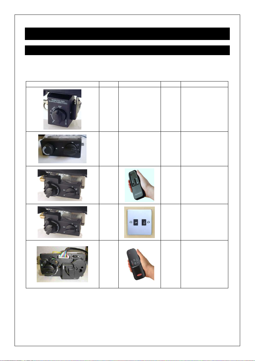
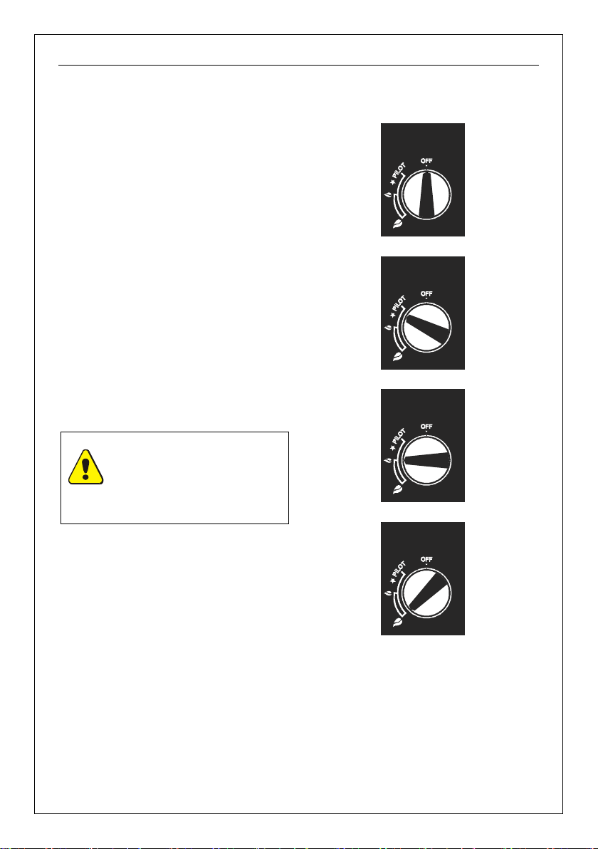
2.1.1. Lighting Procedure (Manual BM Control) ........................................................... 6
2.1.2. Lighting Procedure (Manual Mertik Control) ....................................................... 7
2.1.3. Lighting Procedure (Remote Control) ................................................................. 8
2.1.4. Lighting Procedure (Optimum Control) ............................................................... 9
2.1.5. Lighting Procedure ( otal Control) ................................................................... 10
2.1.6. Manual Operation ( otal Control) ..................................................................... 11
2.2. Battery Replacement (Remote Control and otal Control) ...................................... 12
2.2.1. Handset ........................................................................................................... 12
2.2.2. Receiver Unit ................................................................................................... 12
2.3. Battery Replacement (Optimum Control) ................................................................ 13
2.4. Fuel Effect Layout .................................................................................................. 14
2.4.1. Coal Layout ..................................................................................................... 15
2.4.2. Custom 18 Plus Example Coal Layouts ........................................................... 16
2.4.3. Custom 18 Plus/B and Custom 18 Plus/S Example Coal Layouts (up to 9.5”
deep) 16
2.4.4. Custom 18 Plus/S Example Coal Layouts (up to 11.5” deep) ........................... 17
2.4.5. Pebble Effect Layout ........................................................................................ 18
2.5. Home Improvements .............................................................................................. 23
2.6. Cleaning Instructions.............................................................................................. 24
2.6.1. Cleaning the Fire-Bed and the Imitation Coals/Pebbles ................................... 24
2.6.2. Cleaning the Pilot............................................................................................. 25
2.6.3. Black Painted Metal Surfaces .......................................................................... 25
3. Installation Inst uctions ................................................................................................ 27
3.1. General Safety Requirements ................................................................................ 27
3.2. Flue Requirements ................................................................................................. 27
3.3. echnical Data ....................................................................................................... 28
3.4. Appliance Location ................................................................................................. 29
3.4.1. Floor Level and Raised Fireplace Openings ..................................................... 30
3.4.2. Independent Canopy ....................................................................................... 31
3.4.3. Physical Barrier ............................................................................................... 32
3.5. Ventilation .............................................................................................................. 34
3.6. Contents Checklist ................................................................................................. 34
3.7. Installation Procedure ............................................................................................ 35
2.1.1. Installing the Fire ............................................................................................. 35
3.7.1. Continuation of Installation - Remote Control Model ........................................ 35
3.7.2. Continuation of Installation - Optimum Control Model....................................... 36
3.7.3. Continuation of Installation - otal Control Model ............................................. 37
3.7.4. Continuation of Installation - Detached Control Model ...................................... 38
3.7.5. Commissioning ................................................................................................ 39
3.7.6. Checking for Spillage ....................................................................................... 40
3.7.7. Instructing the User .......................................................................................... 40
4. Se vicing Inst uctions ................................................................................................... 41
4.1. General Requirements ........................................................................................... 41
4.2. Servicing Instructions ............................................................................................. 41

Page ii
4.3. Replacing Parts...................................................................................................... 42
4.3.1. Pilot Assembly Replacement ........................................................................... 42
4.3.2. Injector Replacement ....................................................................................... 42
4.3.3. Control Valve Replacement (BM or Mertik GV34) ............................................ 42
4.3.4. Motor Replacement (Remote Control / Optimum Control Models) .................... 43
4.3.5. Replacing Mertik GV60 Valve ( otal Control) ................................................... 44
4.3.6. Replacing the Receiver ( otal Control) ............................................................ 44
4.3.7. Programming Handset to Receiver ( otal Control) ........................................... 44
4.4. Installation and Operational roubleshooting ......................................................... 45

Page 1
1. G
ENERAL
I
NFORMATION
Int oduction
1. his appliance is suitable for installation in GB and IE and must be installed in accordance
with the rules in force.
In GB, the installation must be carried out by a Gas Safe Registered Installer registered for
working on this type of appliance. It must be carried out in accordance with the relevant
requirements of the:
• Gas Safety (Installation and Use) Regulations.
• he appropriate Building Regulations either he Building Regulations, he
Building Regulations (Scotland), Building Regulations (Northern Ireland).
• he Current I.E.E. Wiring Regulations.
Where no specific instructions are given, reference should be made to the relevant British
Standard Code of Practice (see item 2).
In IE, the installation must be carried out by a Competent Person and installed in
accordance with the current edition of I.S.813 “Domestic Gas Installations”, the current
Building Regulations and reference should be made to the current E CI rules for electrical
installation.
On completion of an installation in IE, it is necessary to complete a “Declaration of
Conformity” to indicate compliance to I.S.813.
2. he installation of the fire in GB should follow the recommendations of the following
current British Standards:
BS 5871: Pt 3 Installation of Decorative Fuel Effect Gas Fires
BS 6891 Pipe work Installation
BS 5440: Pts 1 & 2 Flues and Ventilation
BS EN 1856 Chimneys - Requirements for metal chimneys - System chimney
products
BS 715 Metal flue boxes
IGE/UP/7 IGE document for gas installations in imber Frame Buildings
(Available from CORGI or Institute of Gas Engineers)
3. In other EC countries equivalent rules in force must be used.
4. It is important for correct combustion of this fire that the imitation fuel is placed in
accordance with the instructions given in this and associated booklets. Only approved
imitation fuel, available from Burley Magiglo., should be used with this appliance.
5. It is recommended that a fire guard complying with BS 8423 be fitted for the protection of
young children, the elderly or infirm.
6. his fire is intended for decorative purposes only.
7. he user is warned not to throw any rubbish onto the fire or to disturb the fuel bed.
8. he user is advised that the ceramics used within this appliance require extra care whilst
cleaning. Please refer to the Cleaning Instructions.
9. It is important for the fire to be serviced regularly. An annual service is recommended.

Page 2
Ventilation Requi ements
1. When installing in GB, all models will require a minimum of 100cm2 ventilation in the room
where the fire is installed and reference should be made to BS 5871 Part 3. In IE
reference should be made to the current edition of I.S.813 which makes clear the
conditions that must be met to demonstrate that sufficient ventilation is available.
2. If provided, any purpose provided ventilation must be checked periodically to ensure it is
free from obstructions.
3. When fitting the fire in Northern Ireland (NI), purpose provided ventilation must be
provided in accordance with the rules in force.
4. In other EC countries equivalent rules in force must be used.
Flue Requi ements
1. he flue serving this appliance shall have no cross sectional dimension less than 175mm
(7”) e.g. 225mm (9”) by 225mm (9”) Masonry chimney or 175mm (7”) diameter clay liner.
2. he fireplace size shall be such that there is no spillage from the appliance.
Gas Supply
1. his range of decorative gas fires are suitable for use with Natural Gas (G20) at 20mbar
supply pressure.
2. A separate means of isolating the gas supply must be provided near to the appliance to
facilitate servicing. An isolating valve has been supplied with 18 Plus and 18 Plus/B
models for this purpose.
Decla ation of Confo mity
Burley Magiglo Ltd. declares that the appliance described in “ echnical data” conforms to the
following standard(s) BS EN509:2000 + A1:2003 + A2:2004
Elect ical Supply
Not applicable to this range of appliances.
1.1. Important Note About ODS Pilot
his fire is fitted with an ODS pilot which causes the appliance to shut down in the event of a
reduction of oxygen (e.g. caused by poor ventilation) in the room. Should this happen, follow
the lighting instructions to re-light the fire. In the event that the fire should shut down again,
do NO attempt to re-light it but contact your gas installer for remedial action to be taken.
Under no circumstances should it be adjusted or put out of action by the installer
or the user. In case the pilot needs replacing, only the approved part (available
from your supplier or Burley Magiglo.) should be fitted. Note: if any part of the
pilot assembly becomes faulty the complete assembly will need replacing.

Page 3
1.2. Fire Fret Dimensions
All the Custom 18 Plus range of fires are designed such that they can be installed in fireplace
furniture, e.g. fire baskets, swans nests, etc. here must be an all round clearance of at least
25mm (1”) between the outside edges of the fireplace furniture and the walls of the fireplace
opening. In addition, there must be a minimum free air opening in the fireplace furniture as
indicated in the diagram below.
Minimum opening
(free air) in fire fret
Minimum opening
(free air) in ash pan cover
Figu e 1
Fi e F ont Specification
Free Air Opening in Fire Fret Minimum 15% of total f ont
a ea
Ash Pan Cover Free Air Opening Minimum 5 sq. Inches
(32.3cm2)
NOTE: he free air required through the ash pan door is only required if the
fireplace furniture is enclosed at the sides and to the rear. If this is not the case,
e.g. freestanding basket, then the free air through the ash pan cover is no longer
required, and a solid ash pan cover may be used.
NOTE:: any relevant grate bars will need removing for the fire to fit into the
fireplace opening

Page 4
This page is left intentionally blank

Page 5
2. U
SER
I
NSTRUCTIONS
2.1. Lighting Procedure
Your fire will be fitted with one of the following different types of gas control valves. Identify the
control system on your fire as shown and follow the appropriate operating instructions in the
appropriate section.
Cont o
l Valve
Ope ation
Cont ol Type
+
Manual
=
Manual BM
Cont ol
See
Section 2.1.1
on Page 6
+
Manual
=
Manual Me tik
Cont ol
See
Section 2.1.2
on Page 7
+
=
Remote Cont ol
See
Section 2.1.3
on Page 8
+
=
Optimum Cont ol
See
Section 2.1.4
on Page 9
+
=
Total
Cont ol
See
Sections
2.1.5 & 2.1.6
on Pages
10 & 11

Page 6
2.1.1. Lighting Procedure ( anual B Control)
1. Ensure that the arrow on the control
knob is pointing towards the OFF
position as shown in Figu e 2. Press in
the knob and slowly turn anti-clockwise
until a click is heard. he spark should
now light the pilot. On first lighting, it
may require several attempts to allow the
pilot light to be purged of air.
2. he pilot can be viewed either at the
front centre of the fire, or to the right
hand side.
3. Once the pilot flame is established, hold
the control knob in for approximately 10-
20 seconds and release. he pilot
should now remain alight. Repeat the
procedure if necessary.
4. he arrow should now be pointing to the
PILO position as shown in Figu e 3.
5. If the spark unit fails to light the pilot, the
appliance may be lit manually by
applying a lighted match or taper to the
pilot jet and following the above
procedure.
NOTE: No attempt should be
made to relight the fire for at
least 3 minutes after the pilot
flame has been extinguished
either intentionally or
unintentionally.
7. Once the pilot is established, the main
burner can be operated by turning the
control knob anti-clockwise. he preset
minimum is found with the arrow in the 9
o’clock position as shown in Figu e 4.
8. he preset maximum (as shown in
Figu e 5) is found by turning the control
knob fully anti-clockwise. he control is
infinitely variable between the two preset
limits.
9. o extinguish the main burner, push the
control knob in and turn clockwise until
the arrow is in the PILO position, then
release.
10. o extinguish the pilot, push the control
knob in and turn it clockwise until the
arrow is in the OFF position, then
release.
Figu e 2 - Off Position
Figu e 3 - Ignition Position
Figu e 4 - Minimum Position
Figu e 5 - Maximum Position

Page 7
2.1.2. Lighting Procedure (Upgradeable anual Control)
1. Whilst pushing the IGNI ION KNOB
in (see Figu e 6), turn it
anticlockwise to the pilot flame
position as shown in Figu e 7.
During this process, the spark
ignition will have operated and lit the
pilot flame. On lighting the pilot
flame continue to depress the
ignition knob for a further 15 - 20
seconds then slowly release. he
pilot flame should stay alight. If the
flame goes out, repeat the procedure
above to establish the pilot. Due to
safety and the efficient way the fire
works, it is not unusual for the pilot
to stay alight only after the second or
even third attempt.
2. urn the IGNI ION KNOB
anticlockwise to the main flame
position as shown in Figure 8 .
3. urn the GAS RA E ADJUS ING
KNOB fully anticlockwise (until you
reach the stop position) i.e. the
maximum gas rate. See Figu e 9.
4. he main burner will have cross-lit
from the pilot.
5. Now the gas rate can be adjusted to
the desired setting by turning the
GAS RA E ADJUS ING KNOB to
any position between the pre-sets
high and low.
6. o switch off the main burner turn
the IGNI ION KNOB to the ‘Pilot
burner only Position’ as shown in
Figu e 7. he appliance may be left
in this standby mode if desired.
7. o turn the pilot off turn the Ignition
Knob on the control valve fully
clockwise to ‘’ position.
Figu e 6-Off Position
Figu e 7- Pilot Bu ne Only
Figu e 8- Main Bu ne Ope ational, but gas flow off
Figu e 9-Main Bu ne Ope ation and Max. Gas Rate
NOTE: No attempt should be
made to relight the fire for at
least 3 minutes after the pilot
flame has been extinguished
either intentionally or
unintentionally.
Ignition Knob
Gas Rate Adjusting Knob

Page 8
2.1.3. Lighting Procedure (Remote Control)
1. Press the bottom button on the remote
handset until clicking is heard on the
valve, and the gas rate adjustment knob
is at the off position.
2. With gas available at the valve press the
IGNI ION KNOB in and turn it
anticlockwise to the pilot flame position.
A click of the piezo igniter will be heard
and a spark will appear at the electrode.
At the same time the gas will flow to the
pilot burner and should be ignited by the
spark. Repeat the procedure until the
pilot flame is established.
3. Keep the knob pressed in for a further 10
- 12 seconds and slowly release it. he
pilot flame should stay alight. If the
flame goes out repeat the procedure
above to establish the pilot.
4. If the spark unit fails to light the pilot, the
appliance may be lit manually by
applying a lighted match or taper to the
pilot jet and following the above
procedure.
5. Tu n the IGNITION KNOB
anticlockwise to the Main Bu ne
Ope ation position as shown in Figu e
10.
6. Using the HANDSE (as shown in
Figu e 11) press and hold both the top
and the small button togethe until the
main burner goes to full rate and clicking
can be heard from the valve. During this
process the main burner will ignite from
the pilot.
7. By pressing the two buttons together (to
increase the gas rate) and the lower
button only (to decrease the gas rate)
the valve can be manipulated to select
the desired gas rate between maximum
and minimum. By pressing the buttons in
short bursts you will be able to adjust the
gas rate in small steps.
8. o turn the fire off, continuously press
the lower button until the flame dies
down and clicks can be heard from the
valve. Release the button as soon as
the clicks are heard.
9. he fire can safely be left in this position
at all times, however to prevent
unauthorised or accidental use (say by
children) it is recommended to turn the
IGNI ION KNOB to the pilot flame
position by turning it 90 degrees
clockwise. o turn the pilot off, turn the
IGNI ION KNOB fully clockwise.
NOTE: he clicking sound
made by the valve is the
operation of the valve clutch,
and indicates either maximum
or minimum positions.
IGNI ION
KNOB
FULL RA E
POSI ION
MAIN BURNER
OFF POSI ION
PILO ONLY
POSI ION
MAIN BURNER
OPERA ION
GAS RA E
ADJUS MEN
KNOB
Figu e 10 – Gas Valve
Press these
two buttons
together to
increase
gas rate
Press this
button to
decrease
gas rate
Figu e 11 - Handset Ope ation
NOTE: No attempt should be
made to relight the fire for at
least 3 minutes after the pilot
flame has been extinguished
either intentionally or
unintentionally.

Page 9
2.1.4. Lighting Procedure (Optimum Control)
1. Ensure the main burner is off by pressing
the button on the trim marked
(‘small flame/dot’) until clicking is heard
on the valve (see Figu e 12).
2. With the gas available at the valve press
in the IGNI ION KNOB and turn it
anticlockwise to the pilot flame position
(see Figu e 13). A click of the piezo
igniter will be heard and a spark will
appear at the electrode. At the same
time the gas will flow to the pilot burner
and will be ignited by the spark. Repeat
the procedure until the pilot flame is
established.
3. Keep the knob pressed in for a further 10
- 12 seconds and slowly release. he
pilot flame should stay alight. If the
flame goes out repeat procedure above
to establish the pilot.
4. If the spark unit fails to light the pilot, the
appliance may be lit manually by
applying a lighted match or taper to the
pilot jet and following the above
procedure.
5. Tu n the IGNITION KNOB
anticlockwise to the main flame
position.
6. Press and hold the (‘large flame’)
button (in Figu e 12) until clicking is
heard (fully open).
7. he main burner will have cross-lit from
the pilot.
8. Now the gas rate can be adjusted to the
desired setting by pressing the
(‘small flame/dot’) button. Any rate
between the pre-set high and low can be
obtained using the two buttons.
9. o switch off the main burner press and
hold the (‘small flame/dot’) button
until clicking is heard from the valve
(OFF position).
10. he fire can safely be left in this position
at all times, however to prevent
unauthorised or accidental use (say by
children) it is recommended to turn the
IGNI ION KNOB to the pilot flame
position by turning it 90 degrees
clockwise. o turn the pilot off, turn the
IGNI ION KNOB fully clockwise.
NOTE: he clicking sound
made by the valve is the
operation of the valve clutch,
and indicates either maximum
or minimum positions.
Figu e 12 - Wall Switch
IGNI ION
KNOB
GAS RA E
ADJUS ING
KNOB
GAS VALVE
Figu e 13
NOTE: No attempt should be
made to relight the fire for at
least 3 minutes after the pilot
flame has been extinguished
either intentionally or
unintentionally.

Page 10
2.1.5. Lighting Procedure (Total Control)
1. Ensure that gas is available at the valve
and the ON/OFF switch in the ON
position (–). (See Figu e 14).
2. Simultaneously press and hold the
(red circle) and (large flame)
buttons until a short acoustic signal
confirms the start sequence has begun,
then release the buttons (see Figu e
15).
3. Continuing signals confirm the ignition is
in process. Once the pilot is lit the gas
ate adjusting knob automatically
tu ns to high gas ate. he main
burner cross-lights from the pilot.
4. o adjust the gas rate to desired setting
press the (large flame) to increase the
flame height or (small flame) to
decrease the flame height on the
handset (see Figu e 15).
5. For fine adjustment tap the or
buttons.
6. o leave the burner in the standby
mode press the (small flame) until the
main burner goes out. In the standby
mode the pilot stays alight.
7. o tu n off the main burner and the pilot
press the ‘OFF’ button on the hand set.
WARNING: Ensure that the fire
is operated only whilst present
in the room where it is fitted.
Manual
Knob
Gas Rate
Adjusting
Knob
ON/OFF Switch
NO
MAN
ON
OFF
Figu e 14
Press
these two
buttons
together to
light the
burner
Once lit
use this
button to
increase
gas rate
Once lit
use this
button to
decrease
gas rate
Figu e 15

Page 11
2.1.6. anual Operation (Total Control)
In emergency the appliance can be operated
manually as follows:
1. urn the Gas Rate Adjusting knob fully
clockwise to the OFF position. A clicking
sound will be audible, but this is perfectly
alright.
2. urn the Manual knob clockwise to MAN
position (see Figu e 16).
3. Ensure that the ON/OFF switch is in the
ON (–) position.
4. Using a rigid slender object (like a
screwdriver) depress the pilot valve
operator through the large hole in the
knob (see Figu e 17) and light the pilot
using a match or lighted taper.
5. Keep the valve operator depressed for a
further 10 seconds and slowly release.
he pilot should stay alight. Repeat step
4 if necessary.
6. urn the Manual knob anticlockwise to
the ON position.
7. urn the Gas Rate adjusting knob
anticlockwise to the ON position to turn
the main burner on. Adjust this knob to
obtain the desired gas rate between
maximum and minimum.
8. o turn the main burner off, but leaving
the pilot on, turn the Gas Rate adjusting
knob fully clockwise past the OFF
position.
9. o turn the pilot off place the ON/OFF
switch to OFF (O) position.
M AN
NO
ON/OFF Switch
Manual
Knob
Gas Rate
Adjusting
Knob
ON
OFF
Figu e 16
MA N
NO
Gas Rate
Adjusting
Knob
ON
OFF
Figu e 17
NOTE: No attempt should be
made to relight the fire for at
least 3 minutes after the pilot
flame has been extinguished
either intentionally or
unintentionally.

Page 12
2.2. Battery Replacement (Remote Control and
Total Control)
2.2.1. Handset
1. On the reverse of the handset remove
the battery cover by pressing down at
the top of the cover and sliding down.
2. Remove and unclip the old battery and
replace with a new PP3 9V battery.
3. Replace the cover.
Press here and
slide down
Figu e 18
2.2.2. Receiver Unit
1. Remove the receiver unit from under the
fire burner (or from wherever positioned
if mounted remotely) and remove the
battery compartment cover (see Figu e
19).
2. Replace the old batteries with new ones,
ensuring they are inserted in the correct
polarity.
3. Replace the cover on the receiver unit,
ensuring that it is securely closed.
4. Return the receiver unit to its original
mounting position.
Figu e 19
CAUTION: With the exception of battery replacement, the battery holder must be
located within the heat shield at all times.

Page 13
2.3. Battery Replacement (Optimum Control)
1. he battery pack is mounted inside the
wall-mounting box behind the wall switch
plate.
2. o change the batteries remove the two
small screws securing the wall plate
using a small screwdriver.
3. Remove the battery pack from the wall
box and replace the spent batteries with
new ones (4 off 1.5V AA batteries)
ensuring correct polarity.
4. Insert the battery pack back into the wall
box and refit the wall plate ensuring that
it is the right way up.
5. Secure with screws.
REAR OF WALL
PLA E
CABLE O
VALVE
BA ERY
PACK
(4 x 1.5 V AA
BA ERIES)
LOW/OFF
SWI CH
HIGH
SWI CH
brown
brown
brown
blue
blue
blue
white
black
Figu e 20

Page 14
2.4. Fuel Effect Layout
Your fire has been supplied with either Coal or Pebble effect. Please refer to the relevant
section for instructions on how to arrange the imitation fuels.
Fuel Effect
T ay Type
Refe to
Coal Effect Natural Gas Section 2.4.1
Pebble Effect Natural Gas Section 2.4.5
It is recommended that the imitation fuel be left alone once the desired flame pattern has been
achieved. Constant moving of the imitation fuel will cause the fuel to disinteg ate
and/o cause discolou ation.
RCF Advice:
his product may use Components (Coals, Pebbles & Ceramic backs)
containing Refractory Ceramic Fibres (RCF), which are man-made vitreous
silicate fibres. Excessive exposure to this material may cause irritation to eyes,
skin and respiratory tract.
herefore during installation and servicing we recommend that you use a HEPA
filtered vacuum to remove any dust and soot accumulated in and around the fire
before and after working on the fire, to ensure that the release of fibres from
these RCF articles is kept to a minimum.
We recommend that you should follow the normal hygiene rules of not smoking,
eating or drinking in the work area.
When replacing Components containing Refractory Ceramic Fibres (RCF), we
recommend that the replaced items are not broken up, but are sealed within
heavy duty polythene bags, and clearly labelled as RCF waste. RCF waste may
be disposed of in suitably licensed landfill sites.
WARNING: Do not touch the fire when it is alight. he fire will remain very hot
for a while after extinguishing.
Some sooting on the pebbles may be observed. his is perfectly normal.
Periodically operating the Fire at various rates will burn this soot away. If
excessive sooting is observed, this is an indication that the pebbles are laid
incorrectly – please refer to instructions.

Page 15
2.4.1. Coal Layout
NOTE: As the Burner ray shape and therefore the coal layouts may vary,
ensure that the p inciples of the layouts below are followed.
he Burley Magiglo Custom 18 Plus comes
supplied with four different types of fire bed
refractories (i.e. ceramic coals and aeration
tubes). Each of these are packed in
separate bags which are appropriately
marked. he quantity supplied is dependent
on the size of the burner tray.
Proceed to carry out the coal laying
according to the following instructions and in
conjunction with the drawings on the
following pages.
1. Unpack the small square coals and place
them equidistant along the front edge of
the burner (as indicated in the figures
showing the ‘Fi st Laye ’) taking care
not to cover the cross ignition slot or any
gas entry port holes.
2. Position the aeration tubes over the
shaded areas on the ceramic fibre base.
3. Unpack and carefully place the medium
square coals around the perimeter of the
burner tray so that they are touching
each other as indicated on diagram (as
indicated in the figures showing the
‘Fi st Laye ’). Small gaps between coals
may be left on each side. Ensure that the
first coal on each side is set back a
minimum of ½" and no slots or port holes
are covered. here may be more
medium square coals than required. In
this instance only use sufficient coals to
go round the perimeter as indicated on
diagram.
4. Unpack the random coals and proceed
to bridge them across the aeration tubes,
starting with the middle row as shown on
diagram (as indicated in the figures
showing the ‘Second Laye ’). hen lay
the back row by bridging between
previously laid medium square coals and
aeration tubes. Next lay the front row by
bridging across the previously laid PC05
and the bridging coals in the middle row
making sure that the coals are
adequately stable.
5. Proceed to lay a third layer of random
coals according to diagram (as indicated
in the figures showing the ‘Thi d Laye ’)
making sure that they are not packed
tightly together.
6. Place the coals above the pilot assembly
such that one end of the coal is resting
on pilot shield and the other on
previously laid random coals making
sure that the coals do not rest on the
pilot assembly.
7. Any extra random coals may be placed
at random on top of the third layer to
cover up large gaps in the layout. If the
fire is very deep, these coals could be
placed at the rear of the tray.
8. Small adjustments to the third layer may
be made once the fire is turned on to
alter the flame pattern if desired. A small
pair of tongs may be used to gently re-
position the coals.
9. It is recommended that the coals be left
alone once the desired flame pattern has
been achieved. Constant moving of
the coals causes the coals to
disinteg ate and/o cause
discolou ation.
WARNING: Do not touch the
fire when it is alight. he fire will
remain very hot for a while after
extinguishing.

Page 16
2.4.2. Custom 18 Plus Example Coal Layouts
Aeration ubes
Small Square
Coals
Medium Square
Coals
Figu e 21 – Fi st Laye
Random Coals
Figu e 22 – Second Laye
Random Coals
Figu e 23 – Thi d Laye
2.4.3. Custom 18 Plus/B and Custom 18 Plus/S Example Coal Layouts
(up to 9.5” deep)
Medium Square
Coals Aeration ubes
Small Square
Coals
Figu e 24 – Fi st Laye
Random Coals
Figu e 25 – Second Laye
Random Coals
Figu e 26 – Thi d Laye
This manual suits for next models
2
Table of contents
Popular Outdoor Fireplace manuals by other brands

Berlin Gardens
Berlin Gardens Garden Classic 44"x72" Assembly guide

BCP
BCP SKY6215 instruction manual

Uniflame
Uniflame WAD997SP owner's manual

SNOWJOE
SNOWJOE SUNJOE SJFP28-STN-CL Operator's manual

Suburban
Suburban VOYAGER SOP1001A Owner's operation and maintenance manual

Astria
Astria Polaris36ZEN installation instructions

Blumfeldt
Blumfeldt El Hierro manual

Savannah Heating
Savannah Heating TASMAN 5000 Installation and operating instructions

Outdoor Plus
Outdoor Plus PISMO OPT-2448 manual

Monessen Hearth
Monessen Hearth HWB700OD Installation, operation and maintenance manual

Royal
Royal Gas Fire user manual

KSP
KSP Jensen Geneva 1582LP manual