Magnadyne M45TC User manual

Rearview Mirror/Monitor
R
Model: M45TC
Installation Manual
For Technical Assistance, please call (800) 638-3600,
or visit www.magnadyne.com

This product is intended to assist drivers in the safe operation of backing up and driving a
motor vehicle. Any alteration or modification to the product, the design or the proper instal-
lation of this product in accordance with the installation instructions herein is strictly pro-
hibited. Magnadyne assumes no responsibility whatsoever for any injury or accidental
death resulting from the failure to properly install this equipment.
Warning
2
Introduction . . . . . . . . . . . . . . . . . . . . . . . . . . . . . . . . . . . . . . . . . . . . . . . . . . . . . . . . . . . . . . . 2
Installation Instructions
Mirror Mounting Instructions . . . . . . . . . . . . . . . . . . . . . . . . . . . . . . . . . . . . . . . . . . . . . . 3
Control Box Connection . . . . . . . . . . . . . . . . . . . . . . . . . . . . . . . . . . . . . . . . . . . . . . . . . . . 3
Installing the Temperature Gauge . . . . . . . . . . . . . . . . . . . . . . . . . . . . . . . . . . . . . . . . . . . 3
Installing the Compass Sensor . . . . . . . . . . . . . . . . . . . . . . . . . . . . . . . . . . . . . . . . . . . . . 4
Installing the Mirror Cable Cover . . . . . . . . . . . . . . . . . . . . . . . . . . . . . . . . . . . . . . . . . . . . 4
Electrical Connections . . . . . . . . . . . . . . . . . . . . . . . . . . . . . . . . . . . . . . . . . . . . . . . . . . . . . 5-6
Signal Input . . . . . . . . . . . . . . . . . . . . . . . . . . . . . . . . . . . . . . . . . . . . . . . . . . . . . . . . . . . . . . . 6
Testing and Operation . . . . . . . . . . . . . . . . . . . . . . . . . . . . . . . . . . . . . . . . . . . . . . . . . . . . . . 7-8
Troubleshooting . . . . . . . . . . . . . . . . . . . . . . . . . . . . . . . . . . . . . . . . . . . . . . . . . . . . . . . . . . . 8
Specifications . . . . . . . . . . . . . . . . . . . . . . . . . . . . . . . . . . . . . . . . . . . . . . . . . . . . . . . . . . . . . 8
Index
Introduction
The replacement mirror/monitor can display up to 2 different video inputs. The inputs are
Rearview Camera and Interior View Camera.
Parts/Component List:
1. Rearview Mirror (Qty. 1)
2. Camera Cable (Qty. 2)
3. Control Box (Qty. 1)
4. Filter Box (Qty. 1)
5. Control Box Monitor Cable (Qty. 1)
6. Compass Sensor (Qty. 1)
7. Temperature Sensor (v1)
8. Tapping Screw (Qty. 3)
9. Connector (Qty. 1)
10. Wire Cover (Qty. 2)
11. Double Side Adhesive Tape (Qty. 1)
12. Compass and Temperature Monitor Cable (Qty. 1)
13. Mirror Mount (Qty. 1)

Installation Instructions
3
1. Remove the factory mirror (do not use excessive force). Check to make sure that the facto-
ry mirror mount matches the mounting bracket on the replacement mirror/monitor. If the
factory mirror mount does not fit the mirror/monitor’s mounting bracket, replace with the
extra mirror mount provided.
2.
Slide the mounting bracket onto the mirror mount. Move the bracket back and forth until
completely seated.
3. Tighten the screw in the mounting bracket.
Control Box Connection
Connect the 8-pin extension cable to the rearview mirror/monitor 8-pin cable. Route the cable
under the headliner of the windshield then down the A-pillar behind the plastic shroud to the
under-dash area. Connect the 8-pin cable to the control box 8-pin connector.
Installing the Temperature Sensor:
1. Select a suitable location for the Temperature Sensor outside of the vehicle. The location
should be in the front of the vehicle, between the radiator and front bumper where there will
be airflow. Keep the sensor as low as possible, and as far away from the radiator as possi-
ble.
2.
Use the supplied screw to secure the tem-
perature sensor to the selected location.
3. Route the temperature sensor cable
towards the firewall, securing the cable
where it doesn’t interfere with moving
parts.
4. Pass the terminals through a grommet into
the passenger compartment.
5. Route the wires up to and behind the A-Pillar, then under the headliner towards the Rearview
Mirror.
6. Connect the 2-pin connector from the sensor to the mating end of the Temperature/
Compass Y-cable.
7. Connect the 6-pin Temperature/Compass Y-cable to the rearview mirror/monitor cable.
Mounting the Mirror/Monitor:
Mounting Bracket
Rearview Mirror

4
Installation Instructions
Installing the Compass Sensor:
1. Select a suitable mounting location for the Compass Sensor. The sensor must be mounted
HORIZONTALLY and with the arrow pointing toward the front of the vehicle. Do not mount
near a speaker or magnetic source. Under the dash top panel is a recommended location.
2.
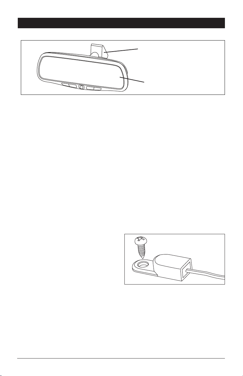
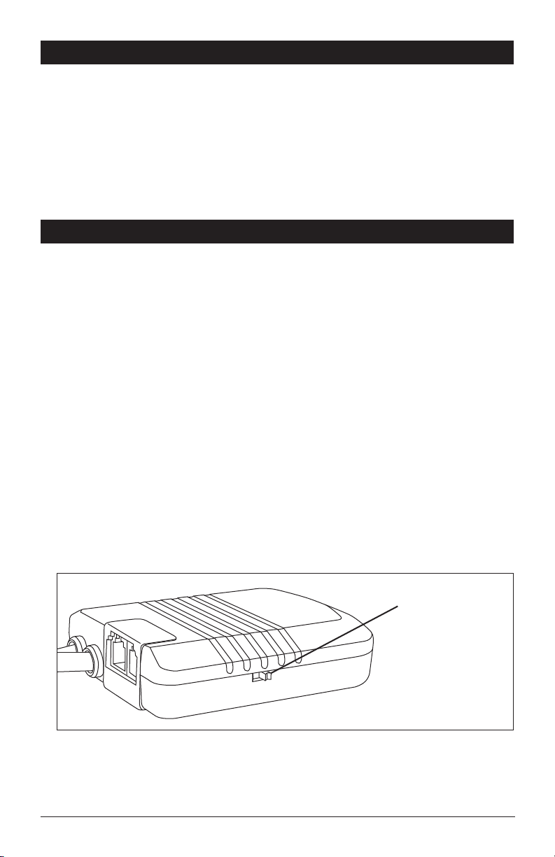
Secure the Compass Sensor using the
screw provided or double-sided adhesive
tape to the selected location with the head
of the compass sensor arrowhead facing
forward.
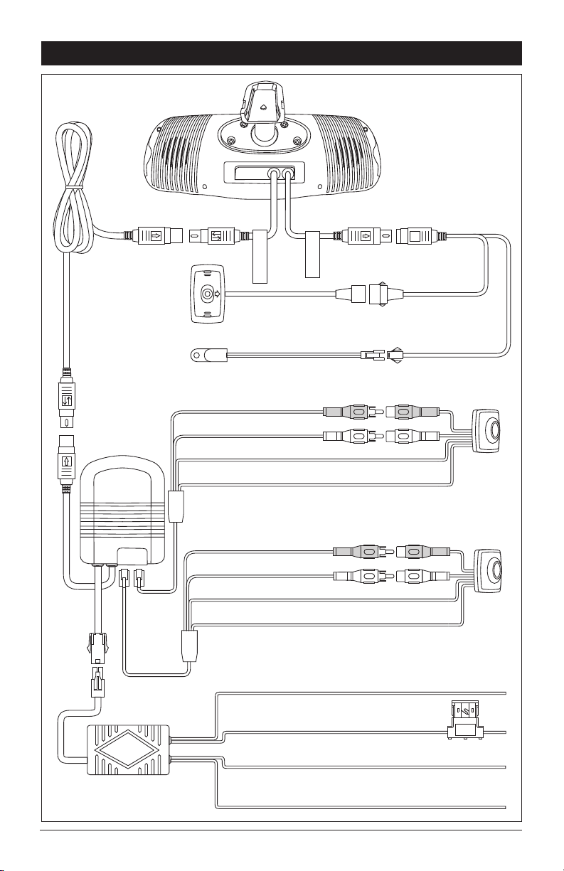
3. Route the Compass Cable up the A-Pillar
and connect the 5-pin Compass Sensor
Cable to the mating 5-pin connector of the
Temperature/Compass Y-cable.
4. Tuck the connectors under the headliner.
Note: Compass must be calibrated before use.
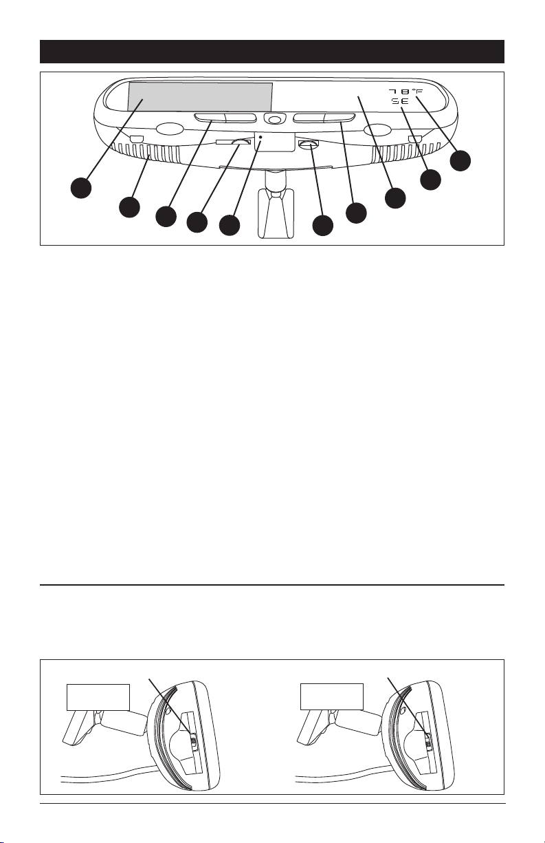
How to Calibrate the Compass Direction:
1. Ensure the Compass Sensor has been
securely mounted.
2.
Position the vehicle so that the front of the
vehicle faces North.
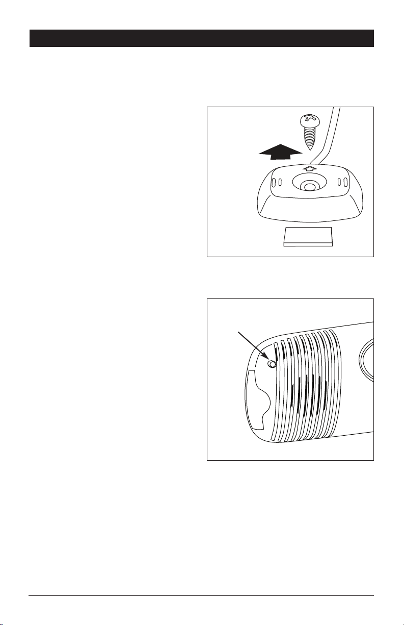
3. Press the Calibration Switch located on the
right rear side of the mirror to the “IN”
position.
4. Drive the vehicle in one or more complete
circles. This process must be 10 seconds
or more in order to calibrate properly.
5. Press the Calibration Switch again, return-
ing the switch to the “OUT” position. Now
the mirror will display the compass direc-
tion accurately.
Toward the Front
of the Vehicle
Double-Sided
Adhesive Tape
Calibration
Switch
Installing the Mirror Cable Cover:
1. Remove the adhesive tape on the base of the cable cover, and stick it to the windshield
next to the mirror’s mounting bracket.
2.
Place the mirror extension cables on the wire cover’s base, and then install the top cover
into the base to cover both cables.
Mount
Horizontally

5
Electrical Connections
Compass
Sensor
Temperature
Sensor
AVin-
2
AVin-
1
Blue Wire Ignition +12V Source
RedWire Fused+12V Constant
Black Wire Ground
Green Wire Reverse Switch
Filter Box
Control Box
Yellow RCA Video In (AVin-1)
White RCA Audio In (AVin-1)
3A
Black Wire Ground
RedWire +12V Constant Rearview
Camera
(Optional)
Yellow RCA Video In (AVin-2)
White RCA Audio In (AVin-2)
Black Wire Ground
RedWire +12V Constant Interior
Camera
(Optional)
Y-Harness
Control Box

6
Electrical Connections
Filter Box:
Blue Wire: Connect this wire to a switched +12 volt power source (a power source turned
on and off by the ignition key).
Red Wire (with Fuse): Connect this wire to a constant +12 volt power source (a power
source that is not controlled by the ignition key).
Black Wire: Connect this wire to the frame of the
vehicle (ground). This wire is the chassis
grounding
wire for the unit.
Green Wire: Connect to reverse light switch (12 volts when vehicle is in the reverse gear).
Control Box:
Camera Input, AVin-1 (Rearview Camera): Plug the RJ11 camera cable end into the control
box AVin-1 port and route the cable to the rearview camera. Connect to the rearview camera
using the RCA connectors.
Yellow RCA: Connect to the video output from the rearview camera.
White RCA: Connect to the audio output from the rearview camera.
Red Wire: Connect this wire to the +12V wire from the rearview camera.
Black Wire: Connect this wire to the ground wire from the rearview camera.
Camera Input, AVin-2 (Interior Camera): Plug the RJ11 camera cable end into the control
box AVin-2 port and route the cable to the interior camera. Connect to the interior camera
using the RCA connectors.
Yellow RCA: Connect to the video output from the interior camera.
White RCA: Connect to the audio output from the interior camera.
Red Wire: Connect this wire to the +12V wire from the interior camera.
Black Wire: Connect this wire to the ground wire from the interior camera.
Camera Input Selector Switch:
a. If using camera inputs AVin-1 (Rearview Camera) and AVin-2 (Interior Camera) place the
switch in the AV-2 position.
b. If using only AVin-1 (Rearview Camera) input place the switch in the AV-1 position.
Signal Input
Mirror Housing:
Compass Sensor: Connect directly to mirror using the Y-harness.
Temperature Sensor: Connect directly to mirror using the Y-harness.
AV-1 AV-2
Camera Input
Selector Switch

7
Testing and Operation
1
367
8
2
CAM T/C
9
10
45
1. 4.5" LCD Monitor
2. Internal Speaker
3. CAM Button (Camera Selection)
a. If you have installed an optional interior view camera with microphone, press the CAM but-
ton to display the image from the interior camera on the monitor and hear the audio from
the internal speaker. Press the CAM button again and the image from the interior camera
will no longer be displayed and the audio will no longer he heard.
b. If you do not have an interior view camera installed, but have installed a rearview camera
with microphone, pressing the CAM button will display the image from the rearview camera
on the monitor but no audio will be heard.
Press the CAM button again and the image from
the
rearview
camera will no longer be displayed.
Note: If the vehicle is put into reverse the rearview camera image will be displayed on the
monitor and the audio can be heard through the internal speaker.
4. LCD Monitor Brightness Control: Rotate the wheel to increase or decrease the brightness of
the monitor.
5. Power On Indication LED
6. Internal Speaker Volume Control: Rotate the wheel to increase or decrease the volume of
the internal speaker.
7. T/C Button (Temperature/Compass): The temperature/compass button switches between
Fahrenheit and Celsius settings and also turns the display On or Off.
8. Rearview Mirror Glass
9. Compass Display
10. Temperature Display
Normal Image (Switch Up) Mirror Image (Switch Down)
IMAGE
IMAGE
Mirror/Normal Image Selectable Switch:
Using the mini-screwdriver to open the left cover, move the switch up for normal image or
switch down for mirror image.
Note: Double check and make sure the image direction is correct before you finish the installa
tion.

Specifications
General:
Power Supply: 12VDC
Power Consumption: <12W
Current Draw: <800mA
Video Input: 1Vp-p/75 Impedance
Audio Input: <=1V
Audio Power Output: 0.5W x 1 (16Ω)
Operating Temperature Range: 0 to 50 Degrees C
Display System:
Screen: 4.5" TFT Color LCD
Brightness: 400cd
Contrast Ratio: 150:1
Backlight Life: 10,000 Hours
Resolution: 960 x 234
Video Format: PAL/NTSC Auto Detect
Display Format: 16:9
© Copyright 2006
Magnadyne Corporation M45TC-IM Rev. A
10-12-06
Troubleshooting
Symptoms Solutions
The Power On Indication LED is not On
after car is started. • Check the installation-wiring diagram.
• Ensure that the parallel red and black line
from the control box is connected properly.
• Check for 12 volts on the blue wire while
the ignition is on.
No video signal appears while reversing
the car. • Check the rearview camera lens.
• Check the rearview camera wiring and
connection
.
• Check that the cable from the rearview
mirror is connected to the AVin-1 port on
the control box.
• Check out the wire connection (to find out
whether the system’s reverse wire cable is
connected to the reverse switch of the car.
Heading information is not accurate. • Calibrate the system (see page 4).
• Check to see if the compass sensor is to
close to a speaker or other magnetic
device
.
• Check to see if the compass sensor is too
close to a steel part.
• Check to see if the compass sensor is
mounted horizontally.
• Check the compass heading direction.
Temperature/Compass display does not
change when T/C button is pressed • Calibration button is pressed “IN”. Press
and release the calibration button to the
“OUT” position (see page 4).
Table of contents