Betriebsanleitung BA012160-001
Stand: 18.05.2010
Seite 2 von 4
Mitgeltende Unterlagen
EG-Konformitätserklärung
DC012160
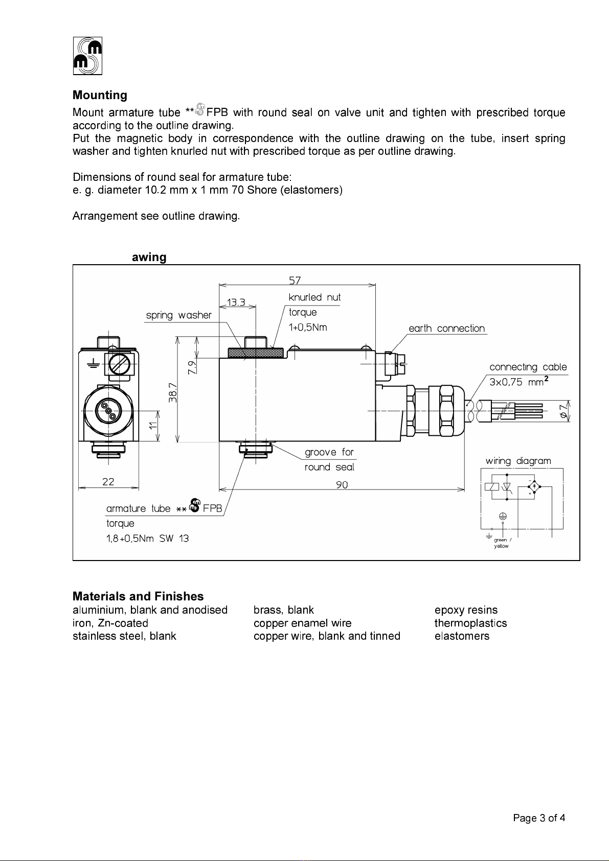
Maßbild: G012160
Hauptmerkmale und
bestimmungsgemäßer Betrieb
Die Einsatzplanung und der Betrieb des
Ventilmagneten haben nach den
allgemeinen Regeln der Technik und den
jeweiligen Vorschriften und Gesetzen zu
erfolgen. Für das Errichten elektrischer
Anlagen übertage, in explosionsfähiger
Atmosphäre, gilt allgemein die IEC/EN
600 9-14.
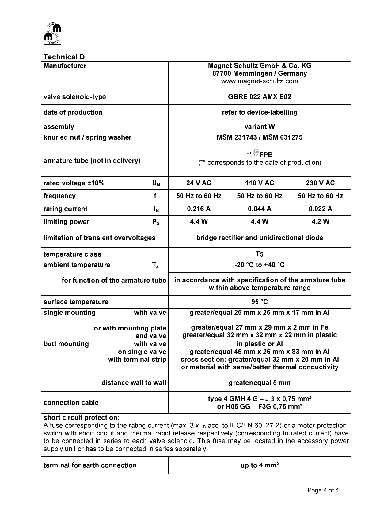
Der Ventilmagnet GBRE 022 AMX E02, in
Ausführung Ex mb II T5 sowie Ex tD A21
IP65 T95°C, wird in Verbindung mit einem
Ankertubus ** FPB als Aktor im
Pneumatikbereich eingesetzt.
Zur Sicherung einer einwandfreien,
gefahrlosen Funktion und langen
Lebensdauer müssen die Hinweise dieser
Betriebsanleitung beachtet und die
technischen Daten gemäß dieser
Betriebsanleitung und der Geräte-
beschriftung eingehalten werden.
Unbeabsichtigte Betätigungen oder nicht
zulässige Beeinträchtigungen sind durch
geeignete Maßnahmen zu verhindern.
Der Ventilmagnet wird mit einer nicht
lösbaren Anschlussleitung geliefert.
Zur Begrenzung der Ausschalt-
überspannung ist intern, parallel zur
Magnetspule, ein Brückengleichrichter mit
Diode geschaltet.
Die Angaben der technischen Daten sind
zu beachten.
Umgebungsbedingungen
Die Verwendung in explosionsgefährdeter
Umgebung ist unter Beachtung der
Gerätebeschriftung und der
Betriebsanleitung vorzunehmen.
Installation und Inbetriebnahme
Diese Arbeiten dürfen nur von einer
Elektrofachkraft mit entsprechender
Qualifikation durchgeführt werden.
Der elektrische Anschluss kann über die
Anschlussleitung außerhalb des
explosionsgefährdeten Bereichs erfolgen
oder über einen Ex-bescheinigten
Klemmenkasten innerhalb des
explosionsgefährdeten Bereichs.
Für den Potentialausgleich ist ein
Masseanschluss außen am Magnet-
mantel vorgesehen.
Die Inbetriebnahme gemäß den
technischen Daten ist nur in Verbindung
mit dem zugehörigen Tubus im
montierten Zustand an der vorgegebenen
Ventileinheit zulässig.
Die Ableitung der Eigenerwärmung darf
durch Überlackieren oder Abdecken der
Geräteoberfläche nicht gemindert werden.
ACHTUNG!
Vor dem Arbeiten an
Stromkreisen und vor dem Öffnen des
Klemmenkastens innerhalb des
explosionsgefährdeten Bereichs sind die
Stromkreise in spannungslosen /
stromlosen Zustand zu schalten.
Im explosionsgefährdeten Bereich dürfen
nur die dafür zugelassenen Werkzeuge
und Messmittel verwendet werden.
Im Störfall sind die Leitungsanschlüsse
und die Stromversorgung im nicht
explosionsgefährdeten Arbeitsbereich auf
ihre korrekte Funktion zu prüfen.
Veränderungen oder Reparaturen am
Magnetkörper und Tubus sind nicht
zulässig.
Wartung
Der Ventilmagnet ist bei
bestimmungsgemäßem Einsatz
entsprechend der Betriebsanleitung
wartungsfrei. Allgemein ist für die Prüfung
und Instandhaltung elektrischer Anlagen
übertage, im explosionsgefährdeten
Bereich, die IEC/EN 600 9-1 zu
beachten.