manuals.online logo
Brands
  1. Home
  2. •
  3. Brands
  4. •
  5. Magnetek
  6. •
  7. Remote Control
  8. •
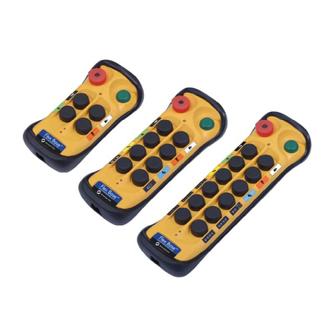
  9. Magnetek FLEX BASE Service manual

Magnetek FLEX BASE Service manual

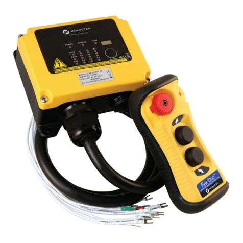
Flex Duo™
Radio Control Equipment
Quick Reference Manual
NOTE: The full Flex Duo Instruction Manual can be found at www.columbusmckinnon.com/magnetek.
Consult the Instruction Manual for any desired feature not included in this quick reference manual.
191-32000-M001 R00
September 2020
© Copyright 2020 Magnetek
N49 W13650 Campbell Drive
Menomonee Falls, WI 53051 Distributed by Tri-State Equipment Company Inc.
[email protected]
www.tsoverheadcrane.com
Tel: (314) 869-7200
Flex Duo Quick Reference Manual
191-32000-M001 R00
September 2020 © Copyright 2020 Magnetek
MRX Wiring Diagram
xIn the single speed model, relay K1 is for PB1 and relay K2 is for PB2.
xRelay K3 is not used in the single speed model.
xIn the dual speed model, relay K1 is first speed for PB1, relay K2 is first speed for PB2, and relay K3 is shared
as a second speed for PB1 and PB2.
Relay
PB1
2ND Speed
PB1
1ST Speed OFF
PB2
1ST Speed
PB2
2ND Speed
K1 X X
K2 X X
K3 X X
xMAIN Relays K27A(NC), K27A and K27B change state when the system is turned on and remain latched while
the system is turned on. When the system is turned off, these relays revert to their normal state.
xFUNC Relay K10 is an auxiliary relay that closes during the START / ON sequence and opens when PB1 and
PB2 are released.
xFor 9-36VDC power supply, wire #1 corresponds to the negative charge (-), wire #3 corresponds to the positive
charge (+), and wire #2 is for GROUND.
xThe circled numbers in the output diagrams above correspond to the wire numbers in the harness.
xSuppressors are recommended on contactors being driven by Flex relays due to the possibility of voltage
spikes.
104mm
O.
56mm
102mm
39mm
O
48mm
.
Receiver Installation
The Flex Duo factory setting uses an internal antenna. If an external antenna kit is required, ensure
the MCX antenna cable located on the RF/decoder board inside the receiver is connected and the
jumper is moved from the INT to the EXT position.
Standard Optional Mounting Bracket













For best reception, the receiver and/or external antenna should always be mounted in a location with a clear line
of sight to the transmitter. Ensure the mounting location of the receiver is not exposed to high levels of electric
noise. Mounting the receiver next to a variable frequency drive or an EMI / RFI generator may cause radio
interference.
Once the proper mounting location is identified, drill four holes (standard) or two holes (optional mounting bracket)
on the control panel, wall, or location where the receiver is to be installed.
If a mounting bracket is used, leave enough slack in the harness to accommodate sliding the receiver on and off
the bracket.
Install Remove










General Operating Procedures
The Flex Duo system consists of the transmitter(s) and receiver containing all of the required settings to work
upon quick installation.
The default operation of the Flex Duo system has the two pushbuttons configured as an interlocked pair to perform
as motion control with the corresponding output relays setup for momentary contact closure. Pressing both buttons
at the same time after start-up will result in no output because the buttons are configured as interlocked.
Turn System On
1. Install the provided batteries in the transmitter and power on the receiver.
2. Elevate the STOP button to power on the transmitter.
3. Perform the START command by pressing and holding both PB1 and PB2 at the same time for 1 second to
activate the receiver MAIN relays and to establish a communication link with the receiver.
When the receiver MAIN relays are activated, the Status LED will change from constant green to constant orange
(system on). Press any pushbutton on the transmitter to begin operation. Pressing any pushbutton prior to
executing the START command at startup will result in no signals transmitted (Status LED blinks orange).
Turn System Off
Press the STOP button down to power off the transmitter, disconnect the receiver MAIN relays, and to disconnect
the communication link with the receiver.
After 5 minutes of inactivity (pushbutton not pressed), the receiver MAIN relays are temporarily disconnected. The
Status LED blinks 3 reds and then shuts off. Press any pushbutton to resume operation.

Other manuals for FLEX BASE

2

Other Magnetek Remote Control manuals

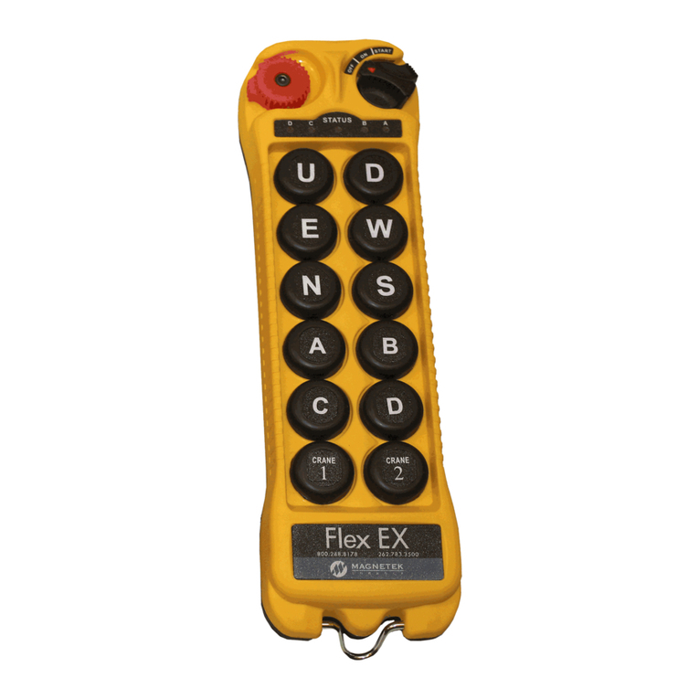
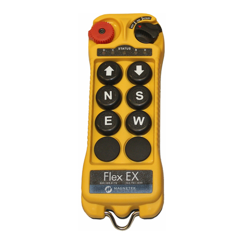
Magnetek Mini-MBT Transmitter Engineered User manual

Magnetek

Magnetek Mini-MBT Transmitter Engineered User manual

Magnetek Flex EM HazLoc User manual

Magnetek

Magnetek Flex EM HazLoc User manual

Magnetek flex 4es User manual

Magnetek

Magnetek flex 4es User manual

Magnetek Telemotive MLTX2 User manual

Magnetek

Magnetek Telemotive MLTX2 User manual

Magnetek CPA HPV 900 Axial Flux PM Series User manual

Magnetek

Magnetek CPA HPV 900 Axial Flux PM Series User manual

Magnetek FLEX BASE User manual

Magnetek

Magnetek FLEX BASE User manual

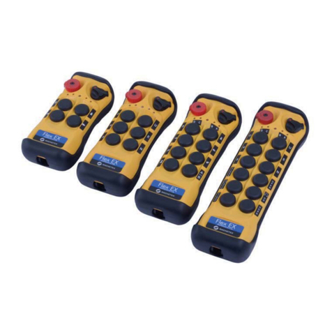
Magnetek Enrange Flex EX User manual

Magnetek

Magnetek Enrange Flex EX User manual

Magnetek Flex 12EX System User manual

Magnetek

Magnetek Flex 12EX System User manual

Magnetek FLEX-6EX User manual

Magnetek

Magnetek FLEX-6EX User manual

Magnetek Flex 12EX System User manual

Magnetek

Magnetek Flex 12EX System User manual

Magnetek FLEX EX2 User manual

Magnetek

Magnetek FLEX EX2 User manual

Magnetek Flex I-Chip User manual

Magnetek

Magnetek Flex I-Chip User manual

Magnetek Flex 4Base User manual

Magnetek

Magnetek Flex 4Base User manual

Magnetek Flex 12EX2 User manual

Magnetek

Magnetek Flex 12EX2 User manual

Magnetek FLEX MINI User manual

Magnetek

Magnetek FLEX MINI User manual

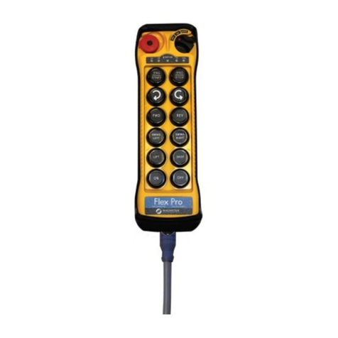
Magnetek Flex Pro Series User manual

Magnetek

Magnetek Flex Pro Series User manual

Magnetek Flex 8RS System User manual

Magnetek

Magnetek Flex 8RS System User manual

Magnetek FLEX BASE User manual

Magnetek

Magnetek FLEX BASE User manual

Magnetek Flex 4EX2 User manual

Magnetek

Magnetek Flex 4EX2 User manual

Magnetek Flex Pro Tethered Controller User manual

Magnetek

Magnetek Flex Pro Tethered Controller User manual

Popular Remote Control manuals by other brands

Topseed TSHD-2401 user manual

Topseed

Topseed TSHD-2401 user manual

Kenwood RC-R0508 instruction manual

Kenwood

Kenwood RC-R0508 instruction manual

Dish Network 20.0 quick start guide

Dish Network

Dish Network 20.0 quick start guide

urmet domus Yokis TLC8C manual

urmet domus

urmet domus Yokis TLC8C manual

Hitachi RC-BGH1FA0G manual

Hitachi

Hitachi RC-BGH1FA0G manual

CAME TOP-432EE manual

CAME

CAME TOP-432EE manual

JABSCO 60020-0000 installation instructions

JABSCO

JABSCO 60020-0000 installation instructions

GRAUPNER Sim-Control 6 manual

GRAUPNER

GRAUPNER Sim-Control 6 manual

Bush URC3541 instruction manual

Bush

Bush URC3541 instruction manual

Insignia NS-GPS4RC101 Quick setup guide

Insignia

Insignia NS-GPS4RC101 Quick setup guide

Mars Comfort-Aire Century DVH 09 Series manual

Mars

Mars Comfort-Aire Century DVH 09 Series manual

Mercado Medic IR 24V 1G Installation and operating instructions in original assembly and handling instructions

Mercado Medic

Mercado Medic IR 24V 1G Installation and operating instructions in original assembly and handling instructions

Ksenia opera KSI7700000.001 user guide

Ksenia

Ksenia opera KSI7700000.001 user guide

Spectrum DX8 instruction manual

Spectrum

Spectrum DX8 instruction manual

HMS Netbiter user manual

HMS

HMS Netbiter user manual

Scientific Atlanta ER1 user guide

Scientific Atlanta

Scientific Atlanta ER1 user guide

Leviton HCCKR operating instructions

Leviton

Leviton HCCKR operating instructions

EILEEN GRAYS RE-022 General information

EILEEN GRAYS

EILEEN GRAYS RE-022 General information

manuals.online logo
manuals.online logoBrands
  • About & Mission
  • Contact us
  • Privacy Policy
  • Terms and Conditions

Copyright 2025 Manuals.Online. All Rights Reserved.