Magneti Marelli TPMS Connect EVO 007935900385 User manual

Magneti Marelli Aftermarket Spółka z.o.o.
Plac Pod Lipami 5, 40-476 Katowice
Tel.: + 48 (032) 6036107, Faks: + 48 (032) 603-61-08
e-mail: [email protected]
www.magnetimarelli-checkstar.pl
Tpms Connect Evo Control, Diagnosis, Universal Sensor
Programming And Coding Tool For Tpm Systems
User’s Manual
007935900385

Foreword
Dear Customer,
Thanks for choosing our product. This product has been designed to give you years of
satisfactory service. To ensure this, please read this User Manual thoroughly before
using the product and keep the manual in a safe place for future reference.
Our exhaustive range of products sets a new standard in TPMS (Tire Pressure
Monitoring System) diagnostics while offering an aesthetically pleasing design.
All of our products are designed and manufactured to the highest quality standards.
TPM-II will prove to be an indispensable tool for:
Checking sensor operation before servicing the tires (when vehicle is brought in
for service or repair).
Establishing proper operation of the TPMS system when the customer picks up
the vehicle.
Determining why the “Tire Pressure” (TPMS) light turns on.
Ensuring that sensor provides accurate pressure and temperature readings.
Measuring wireless the pressure of tires (with no need to unscrew valve cap and
connect a compressed air line with pressure gauge).
Enabling time-saving, safe repair procedures with reference information (such as
torque figures or part numbers) always handy to avoid damage due to improper
procedures.
Ensuring that sensors are refitted in their original positions after service
(positioning tool)
Programming of programmable sensors like SensIT and EZ sensor to replace a
defective OEM sensor
Perform a TPMS coding operation after a sensor replacement.

Instrument first use:
The battery has been partially charged, but it may be
necessary to recharge it before using the instrument.
Note: batteries must be charged and discharged once
every three months to ensure a battery longer life.
1. Symbols used in the manual
This symbol calls attention to important information concerning
operation and safety.
This symbol calls attention to important information and tips aimed at
ensuring proper operation of the equipment.
This symbol calls attention to important instructions concerning
maintenance of electrical parts.
This symbol calls attention to important service instructions.

2. Safety rules
To recharge the equipment, it is mandatory to use the power supply
unit supplied. Item No. 1800155. The manufacturer shall not be liable
for damage to equipment in the event when other power supply units
are used.
This appliance has been designed and tested to ensure safe operation.
The user is required to observe the information and warnings provided in
this manual to ensure safe operation and preserve the safety features of
the appliance.
WARNING : For equipment package maintenance and handling after
equipment installation, the provisions of Legislative Decrees DDLL 626 of
19/9/94 and 242 of 19/3/96 apply. Use appropriate tools to open
package.
CAUTION: USE UTMOST CARE !!!
Do not allow operation of this equipment by unqualified persons.
It is the owner's responsibility to keep warning labels and rating plates
clean and legible.
This manual is subject to changes and updates.
Be sure to read the update and customization instructions included in
this manual.
The manual is divided into sections for ease of reference. Manual
instructions - especially those concerning maintenance - are intended for
use by specialized technical personnel with good knowledge of
mechanics, electro mechanics or of the operation of computerized unit-
based systems. The system has been designed to facilitate operation and
troubleshooting, with a wide range of display messages providing

detailed indications to help locate problems.
Please read these instructions carefully before operating the equipment.
Collect this manual and all literature supplied with the equipment in a
file folder and keep it with the machine where operators can easily
access it.
Make sure installation has been performed in compliance with all
applicable regulations and standards.
Read this manual carefully and learn how to use the equipment properly
and safely.
Be sure to observe applicable accident prevention rules when operating
and servicing the equipment.
In the event of unauthorized changes to the equipment, the
manufacturer shall not be liable for any resulting damage or incident.
Please note that bypassing or removing safety devices is in violation of
workplace safety rules in force in the user's country.

3. Upon receipt
Upon receipt, check packing and product components for damage in the presence of the
carrier. Liability for transport damage attaches to the forwarding agent or carrier.
Report any damage, giving details of the nature and severity of the damage, in the
shipping document and file a claim against forwarding agent or carrier.
4. What is a TPMS system?
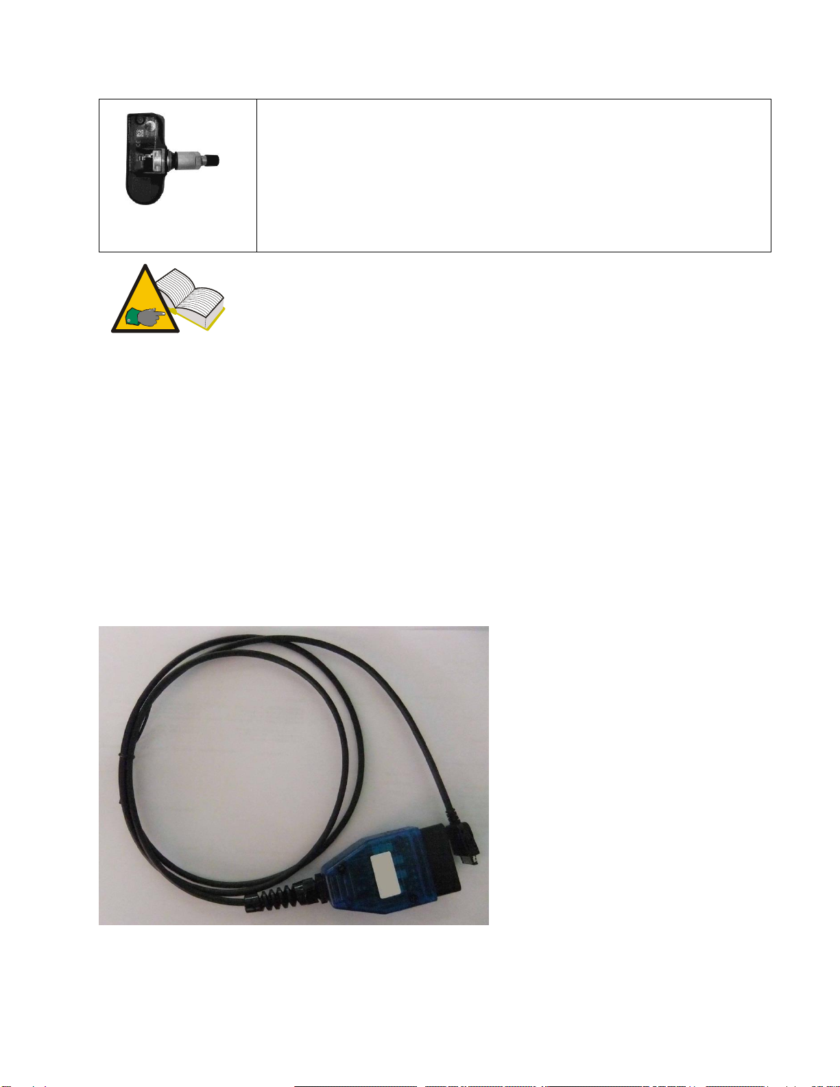
The TPMS or Tire Pressure Monitoring System continually monitors tire pressures and
temperatures and sends the information to the vehicle’s body computer to have it
displayed on the instrument panel. The system is made up of an ECU placed inside the
vehicle cab that receives radio frequency pressure and temperature signals from four
sensors installed inside the tires.
When the vehicle is running, the sensors transmit their signals every 20-30 seconds
approximately. In the event of a significant pressure variation, transmission interval is
shortened to 8-10 seconds.
When the vehicle is at standstill, transmission interval may vary between 10 and 40
minutes, depending on the type of sensor installed.
5. TPMS indicator lights
Outlined below are the most significant TPMS indicator lights.
Depending on the type of vehicle, this light may
indicate one of the following conditions:
Turns on to indicate that the pressure of
one or more tires is above or below the
specified rated pressure.
Turns on to indicate a TPMS malfunction
(for instance, when one of the sensors is
malfunctioning).
Light operation may vary to differentiate
indications when tire pressure has crossed
the warning or alert thresholds.

Tire location indicator
This light indicates the location of the under- or
overinflated tire.
The light may be associated with a display
message.
Display messages
“Check tire pressure”
Audio Alarms
Audio alarm for wrong tire pressure or TPMS
malfunction
6. Type of sensors
Sensors may be grouped into two broad categories, depending on whether they are
incorporated into valve body or not as shown in the table below.
Design 1
The valve shown in the figure is made up two elements:
-pressure sensor
-valve body
Valve body is made up of four elements: retaining screw, valve, nut
and valve cap.

Design 2
The valve shown in the figure is a single component that incorporates
both pressure sensor and tire valve. This valve design also features a
grommet/O-ring (to keep air from escaping past the hole in the rim),
a nut and the valve cap.
In design 1, valve and sensor may be replaced separately when
needed; in design 2, valve and sensor are replaced as a set.
7. Package contents
Package contains:
1 TPM-II sensor diagnostic tool
1 SD CARD
1 USB connection cable for PC connection
1 CD-ROM with product update utility
1 External Power Supply.
1 Manual
8. OBD Option

Through this optional it is possible to connect the tool to the ECU of the vehicle in order
to carry out the following procedures:
Flashing the ECU when the sensor is replaced
Flashing the ECU when rotating the tires
Adjust when possible the alarm threshold, set the winter tires etc.
Read and delete the malfunctions (Diagnostic Trouble Code)
The optional kit includes intelligent OBD cable and software
9. Maintenance and care
Please follow these instructions to avoid malfunction or unexpected failures:
-Do not drop or knock the equipment.
-Avoid spilling fluids on the equipment.
-Do not use batteries other than those specified in this manual.
-Do not service the equipment when it is in operation.
-Do not clean the equipment when it is in operation.
-Keep the package for safe handling
10.First Product Activations
Please check that with this device you receive also a sheet with the
password to activate it
Use of diagnostic software require an user license. There are 2 different type of User
License:
1. Sensor Diagnosis user license. This license permits to diagnose tpms sensor.

2. ODB Diagnosis User license. This license include sensor diagnosis and OBD TPMS
diagnostic .
Each license include European, Asian and USA vehicle.
Each user license is activated with a password directly on the tool. Password is released
from your distributor. If password is not putted on the tool, it doesn’t work.
Each activation password released is based on the following information:
1. Device Serial Number
2. Type of User License
Password contains an expiration date and this date is the same date when it was
generated. With the password it is possible to download from the website, update and
activate the tool with the database coverage available at the expiration date of the
password.
When the password is expired will expiry you can download a new
database coverage from the website but you can’t activate it on the
TPM tool. Please refer at your distributor to subscribe a new 12 months
software update
11.Subscription
At first activation (or subscription) a password will be issued . When it is expired it is
important to renew your subscription to continue the possibility to update tpms
database coverage. There are 2 different types of subscription:
1. Sensor Diagnosis subscription. This subscription include:
12 months update database coverage to diagnose tpms sensor.

Sensor Clone Driver user license and 12 months update
12 months free update database coverage of universal sensor programming
supported
2. ODB Diagnosis subscription.
12 months update database coverage to diagnose tpms sensor.
Sensor Clone Driver user license and 12 months update
12 months free update database coverage of universal sensor programming
supported
12 months TPMS OBD diagnostic update
12.How to power on/off the equipment
Touch the key to power on the equipment.
Keep key pressed down to power off the equipment.
The equipment will power off automatically when no buttons have been pressed for 10
minutes to save battery life.
13.Recharging the equipment (par.7)
The batteries placed inside the equipment are charged. The equipment may only be
recharged using the supplied power supply . In the event the equipment should run
fully flat, it will take about 3 hours to fully recharge it.

14.Settings
Step
Screen shot
Description
1
Select option SETUP from the main menu page to
enter the settings menu
2
LANGUAGE user can choose the required language.
Many languages are available from: French, Italian,
English, Portuguese, Spanish and German
3
MEASURMENT UNIT user can choose different
parameters to display the value.
Pressure (bar / psi / KPa)
Temperature (C/F)
Torque (Nm / FtLbs)
4
FREQUENCY it’s possible to setup the Operating
Frequency of the tool.
USA (315Mhz)
EUROPE (433Mhz)

5
DATABASE it is possible to choose a European or
American (US) database.
Europe : officially imported in EU
USA : parallel import or US market
6
Selecting ALARM it’s possible to enable or disable
SOUND and VIBRATION
7
RELEASE the tool will show software info’s:
Firmware VERSION
Database VERSION
Serial number: XXXXXX

15.PASSWORD INPUT
There are 2 different ways to activate the tool:
Insert the password on the tool itself
Insert the password with the PC software update program while PC is
connected at the tool.
Step
Screen shot
Description
1
Select the “SETUP” option from the main menu
2
Select PASSWORD.
3
Enter the password to enable the activation of the
software. It also releases the functions ordered. The
password contains an expiration date that relates to
the licence activation date plus one year.

16.Software Version
Step
Screenshot
Description
1
Select the “SETUP” option from the main menu
2
Select Release.
3
Software version information or activation
Main information displayes:
Fw version Displayed on the first line. This indicates the version of the user
interface.
DB version. This version indicated the database version availableon the tool
DB Authoriz. This version indicated the database version activated on the tool
Expiration Date Indicates the date of subscription expiration.
Serial Number: is the serial number of the tool.

17.PC Software & Driver Installation
When installing new software, please remove the old version before
the new installation.
Before software installation, please be sure that you have
“administrator” privileges.
STEP
Screen shot
Step Description
1
Insert the CD-ROM into the PC.
Setup Software starts automatically.
(When enabled)
If the setup installation doesn’t
start, use the following procedure:
Computer on the desktop or
Start button
CD-ROM/DVD unit
Double click on the setup
2
Select the language of the
installation.

3
Read carefully the “License
Agreement”. If you agree, please
select “I accept”. Selecting “I don’t
accept the agreement” will result in
the software not being installed
4
Select the path of installation.
5
Follow the other displayed
indications. At the end of the
installation, the setup requires a
PC restart.
6
After the PC restart, please check
that you have:
A new icon on the desktop
regarding the TPMS Manager
software.
A new group program
regarding the TPMS manager
software.

To avoid problems during the installation and the software setup, it is
suggested that the Firewall and the Antivirus Software should be
deactivated until the processes are complete.
17.1. Language setting on TPMS MANAGER SW
STEP
Screen shot
Description
1
Launch TPMS manager
software by clicking on the
icon on the desktop.
After starting up the
program click on the flag
icon in the right upper
corner of the program
screen.
2
Select your language
pushing on relative flag
button

17.2. TPM II–PC Setup Communication
Wireless communication reduces the number of wires/cables in the
workshop. This reduces both obstacles interfering with people’s
movement in the shop and mechanical shock from the PC or TPM II tool
due to accidental collision.
The TPM II can communicate with a PC in 2 different ways:
- USB
- Bluetooth wireless communication
On the tool is showed which communication type is enabled
There is no USB symbol found in the tool
when the tool is connected to a pc
Bluetooth symbol is present see picture.
17.3. Bluetooth Setup
Before proceeding with this section, be sure that the Bluetooth driver
for the Bluetooth peripheral on the PC is correctly installed.
To avoid conflict with the driver and the software management, please
check that only 1 Bluetooth peripheral is active on the PC.
The Bluetooth on the TPM II tool is a device classified as Class 1
distance in open space (space without any obstacle). Please use a
Bluetooth peripheral device PC of at least Class 1 to ensure proper
communication in a workshop area ranging between 15-20m from the

car.
A homologated Bluetooth dongle is optional available. We advise using
this dongle to prevent disappointments as not all dongles are the same.
17.4. Bluetooth Setup for Windows 7
The procedure depicted in this paragraph is valid only for the Windows 7 operating
system. The same procedure can be followed for other operating systems using the
different windows and setups specific for that operating system.
Please carefully check that the Bluetooth driver is installed in and supported by your
operating system.
STEP
Image
Description
1
Open in sequence the following
items on the PC:
Select the Windows Button
Select: Printer & Devices
Select: Add new device
2
Switch ON the TPM tool
Table of contents
Other Magneti Marelli Measuring Instrument manuals
Popular Measuring Instrument manuals by other brands

Dragino
Dragino LHT65N user manual

Endress+Hauser
Endress+Hauser Proline Prosonic Flow P 500 operating instructions

Agilent Technologies
Agilent Technologies 83483A manual

PCB Piezotronics
PCB Piezotronics 353B32 Installation and operating manual

Ninglu
Ninglu AM706-H Operation & installation manual

MyTek
MyTek DDD-603 Reference manual