Model OE-10
Installation, Operation and Maintenance
Page 10
Rev. 4/20/07
A2151_MAGNUM.doc
FINAL ADJUSTMENTS (CONTINUED)
SYNCHRONIZING CABLES
41) Raise lift and insure carriages lower into
same lock position.
42) Adjust synchronizing cables so the tension is
equal in both cables and carriages are firmly
sitting on locks.
43) Cycle lift to insure that latches operate
simultaneously.
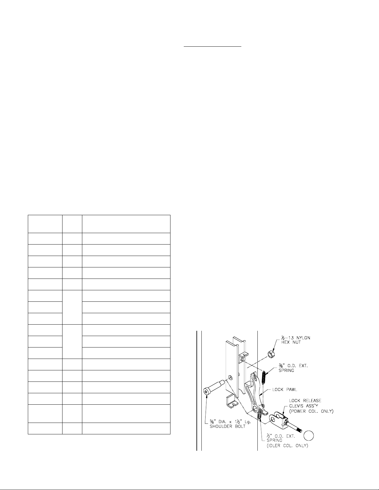
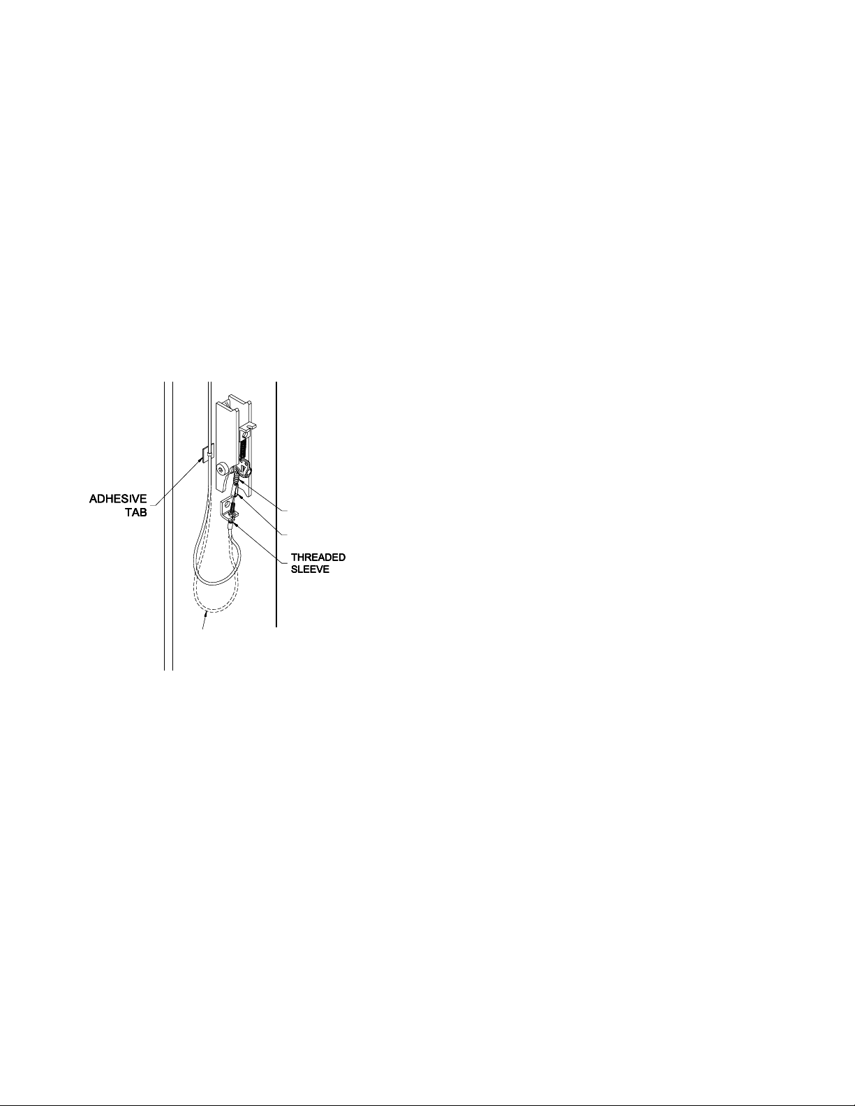
LOCK RELEASE CABLE
44) Lower lift to the floor and snap plastic cover
over Power Column lock assembly.
45) Pull and release Power Column lock release
handle while watching Idler Column lock.
Adjust lower threaded sleeve cable adjuster
jam nuts on Idler Column until Idler Column
lock disengages and engages fully. When
properly adjusted, the idler column lock
should just come to rest against the back of
the column when engaged and fully out
against the tab when disengaged. Tighten
Idler Column lower tab jam nuts.
IMPORTANT: IF IDLER SIDE LOCK PAWL DOES NOT
FULLY DISENGAGE, DAMAGE MAY RESULT TO IDLER
SIDE CARRIAGE AND OR CABLE SYNCHRONIZING
SYSTEM.
46) Tighten threaded sleeve cable adjuster jam
nuts and install lock release knob.
47) Tighten and trim wire ties.
48) Snap plastic cover over Idler lock assembly
(align release cable with notches in cover).
OWNER/OPERATOR CHECKLIST
49) Demonstrate the operation of the lift to the
owner/operator and review correct and safe
lifting procedures using the Lifting It Right
booklet as a guide.
50) Complete the Installation Checklist/Warranty
Validation questionnaire with the owner.
Review the terms of the warranty registration
card, and return the card and a copy of the
questionnaires to:
Challenger Lifts, Inc.
200 Cabel Street
Louisville, KY. 40206
OPERATION PROCEDURE
SAFETY NOTICES AND DECALS
This product is furnished with graphic safety
warning labels, which are reproduced on
page 3 of these instructions. Do not remove
or deface these warning labels, or allow them
to be removed or defaced. For your safety,
and the safety of others, read and understand
all of the safety notices and decals included.
OWNER/EMPLOYER RESPONSIBILITIES
This lift has been designed and constructed according
to ANSI/ALI ALCTV-1998 standard. The standard
applies to lift manufactures, as well as to owners and
employers. The owner/employer’s responsibilities as
prescribed by ANSI/ALI ALOIM-2000, are summarized
below. For exact wording refer to the actual standard
provided with this manual in the literature pack.
The Owner/Employer shall insure that lift
operators are qualified and that they are trained
in the safe use and operation of the lift using the
manufacturer’s operating instructions; ALI/SM
93 -1, ALI Lifting it Right safety manual; ALI/ST-
90 ALI Safety Tips card; ANSI/ALI ALOIM-2000,
American National Standard for Automotive Lifts-
Safety Requirements for Operation, Inspection
and Maintenance; ALI/WL Series, ALI Uniform
Warning Label Decals/Placards; and in case of
frame engaging lifts, ALI/LP-GUIDE, Vehicle
Lifting Points/Quick Reference Guide for Frame
Engaging Lifts.
The Owner/Employer shall establish
procedures to periodically inspect the lift in
accordance with the lift manufacturer’s
instructions or ANSI/ALI ALOIM-2000, American
National Standard for Automotive Lifts-Safety
Requirements for Operation, Inspection and
Maintenance; and the employer shall insure that
the lift inspectors are qualified and that they are
adequately trained in the inspection of the lift.
The Owner/Employer shall establish
procedures to periodically maintain the lift in
accordance with the lift manufacturer’s
instructions or ANSI/ALIOIM-2000, American
National Standard for Automotive Lifts-Safety
Requirements for Operation, Inspection and
Maintenance; and the employer shall insure that
the lift maintenance personnel are qualified and
that they are adequately trained in the
maintenance of the lift.
The Owner/Employer shall maintain the
periodic inspection and maintenance records
recommended by the manufacturer or ANSI/ALI
ALOIM-2000, American National Standard for
Automotive Lifts-Safety Requirements for
Operation, Inspection and Maintenance.
The Owner/Employer shall display the lift
manufacturer’s operating instructions; ALI/SM
93 -1, ALI Lifting it Right safety manual; ALI/ST-
90 ALI Safety Tips card; ANSI/ALI ALOIM-2000,
American National Standard for Automotive Lifts-
Safety Requirements for Operation, Inspection
and Maintenance; and in the case of frame
engaging lift, ALI/LP-GUIDE, Vehicle Lifting
Points/Quick Reference Guide for Frame
Engaging Lifts; in a conspicuous location in the
lift area convenient to the operator.