- 6 -
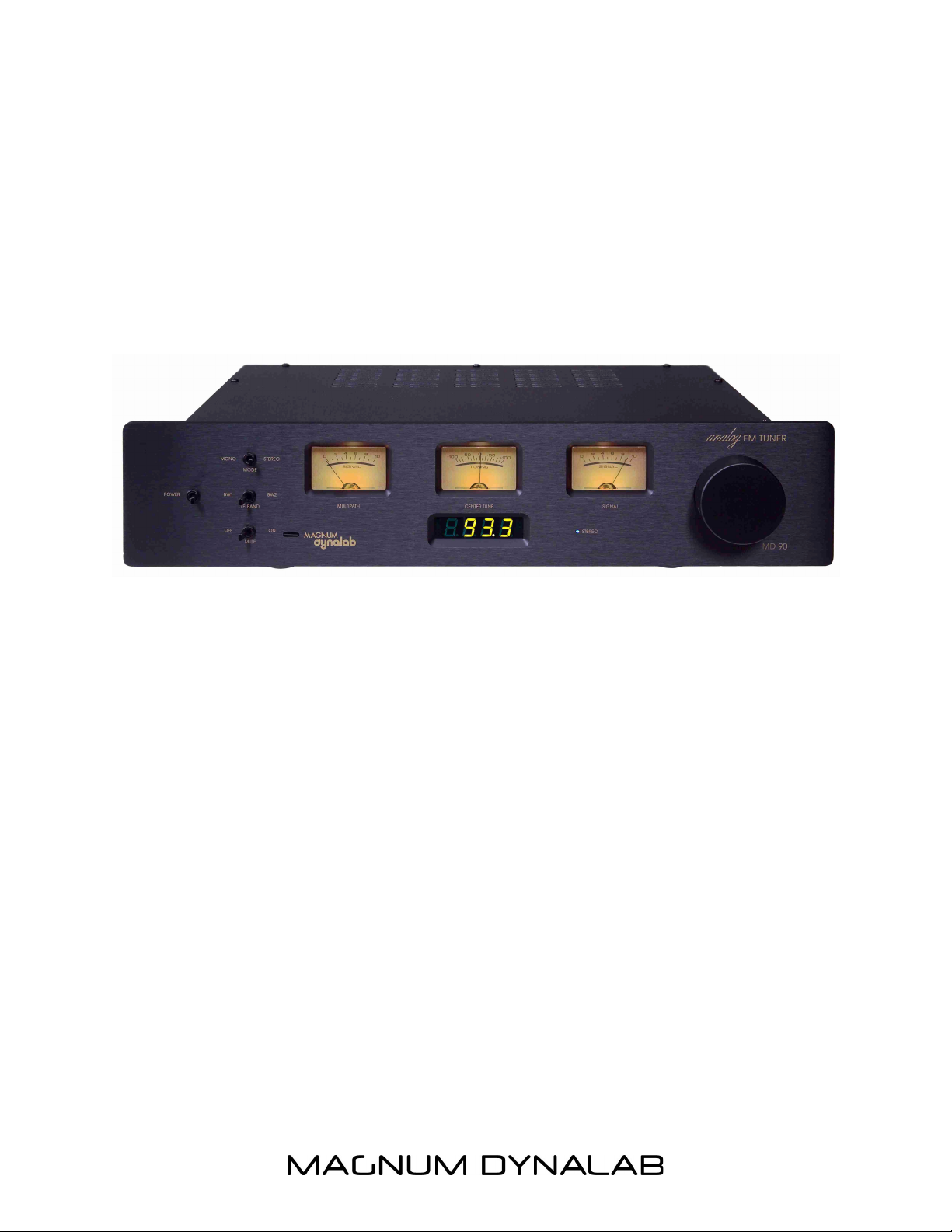
CONTROLS AND FUNCTIONALITY
(Letters correspond with image on the following page)
A. POWER – Turns the power (AC) on and off to your tuner, with the optional remote
system this switch must be left in the “OFF” position.
B. STEREO – Switches your tuner from Stereo to Mono and vice-versa. Switching to
Mono will often clean up noisy stereo transmissions and aid in delivering quiet
listening to weaker signals.
C. I.F. BANDWIDTH – When BW 1 is selected your tuner is in the wide IF
(Intermediate Frequency) bandwidth setting. This setting produces the best sound
possible where strong adjacent channel interference is not an issue. When BW 2 is
selected the tuner is placed in the “Narrow” bandwidth setting, this setting produces
optimal sound performance where adjacent channel interference is a factor.
D. MUTE/DIGITAL INPUT – In the “ON” position, a limit is now placed on your tuner.
While scaling up and down the FM dial, weak stations will be overlooked so that no
alarming noises will be heard while looking for programs. We recommend that with
the optional remote system you leave the Mute switch in the “ON” position. If you
chose the Digital Audio Converter (D.A.C.) option, a three position switch will have
been installed with a USB 2.0 input. In the “D1” position, the RF section of the tuner
is bypassed, therefore offering full control to the D.A.C.
E. TUNING NOB – Rotating this knob allows you precise control of the fine tuning of
the FM signal you are listening to. Slight de-tuning of the tuner may aid in eliminating
measures of multi-path or other atmospheric conditions that may affect the sound
quality of your reception.
DISPLAYS AND METERS
(Letters correspond with image on the following page)
F. MULTI-PATH METER – This meter indicates multi-path (multi-path is the same FM
signal being received by your antenna and tuner at two different time intervals). Your
multi-path meter should read ero. If this meter reads more than ero, move your
antenna to a different location or rotate your antenna so that your meter reads ero.
If this does not correct the problem a better or different antenna system may be
required, please visit the Reception Techniques section in this manual.
G. CENTER TUNER METER – Indicates the setting of the tuners front end in relation to
the station you are tuning to. In normal situations this needle should be tuned to the
central point of this meter.
H. SIGNAL STRENGTH METER – The signal strength meter indicates the strength of
your incoming FM signal, the higher the better. This meter is calibrated to never hit
10, this is done to protect the meter mechanism.