Industrial Gaussmeter IGM11 Operating Instructions
Page 3 / 106
magnet
systeme
ersion 01/2013 © 2013 MAGSYS magnet systeme GmbH - All Rights Reserved
Table of Contents
1 Safety Instructions 6
1.1 Safety Instructions for the Device 6
1.2 Safety Instructions for Measuring Probes 6
1.3 Safety Symbols 7
2 Brief Intro uction 8
2.1 Preparing a Measurement 8
2.2 Running a Measurement 8
2.3 Measuring Unit 9
2.4 Selecting the Measuring Range 9
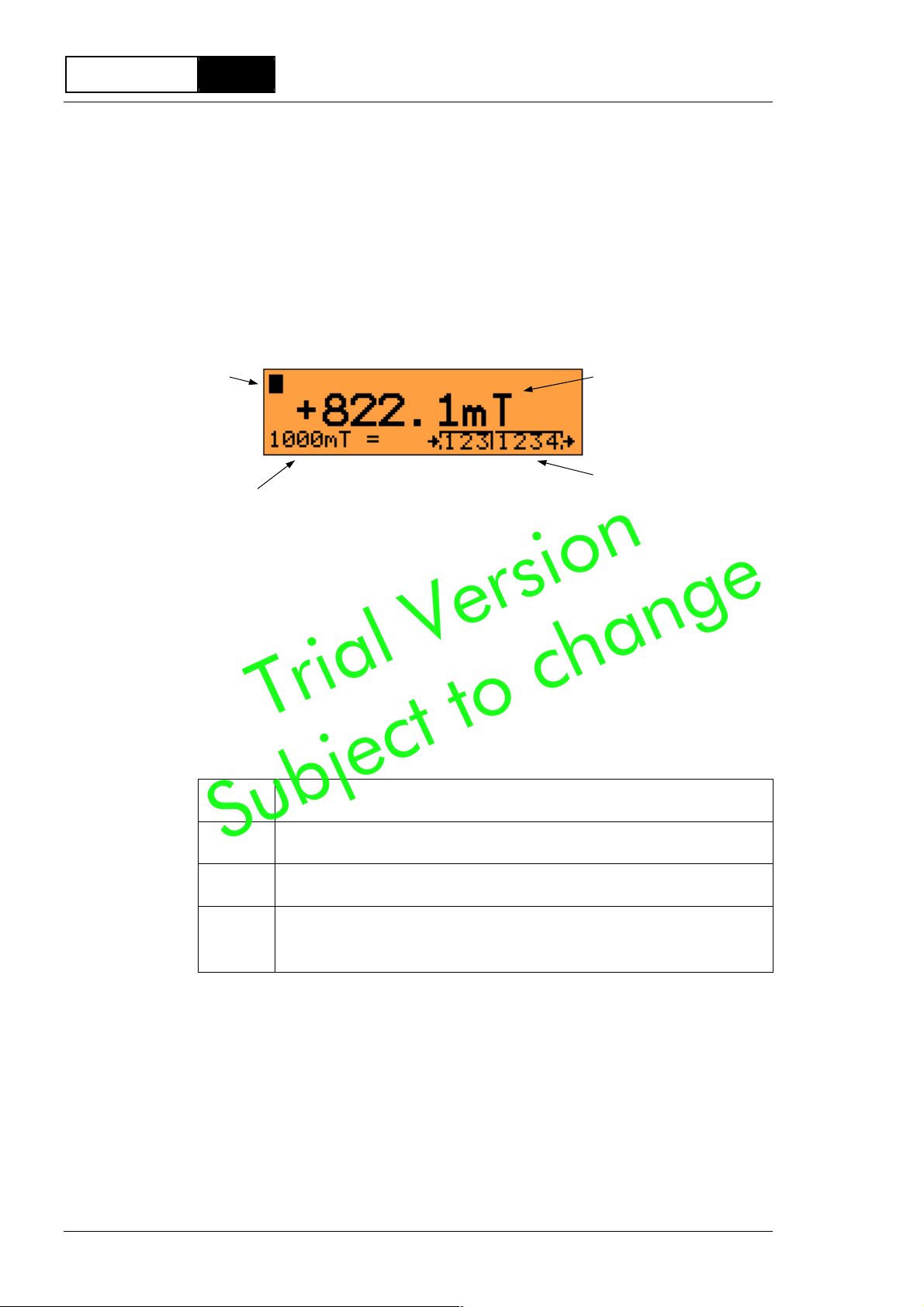
2.5 Display 10
2.6 Status Display 10
3 Function of the Gaussmeter 11
3.1 The Hall Effect 11
3.1.1 Linear Properties of the Hall Probe 11
3.1.2 Non-linear Properties of the Hall Probe 12
3.2 Measurement Details 14
3.2.1 Sample Measurements with an N FeB
Magnet 14
3.2.2 Remanence an Hall Gaussmeter
Measurement 15
3.2.3 Accuracy Base on Positioning an
Direction 16
3.2.4 External Static Magnetic Fiel s 17
4 Control Elements an Connections 18
4.1 Front Panel Overview 18
4.2 Ports Overview 19
4.3 Power Supply 20
4.4 Probe Connection 20
4.5 USB Interface 21
4.6 LAN Interface 22
5 Operation 24
5.1 Buttons 24
5.2 Display 25
5.3 Status Display 26
5.4 Null Balance 26
5.5 Measuring Range 27
5.6 Measuring Unit 28
5.7 DC/AC Fiel Measurement 28
5.7.1 DC Fiel Measurement 28
5.7.2 AC Fiel Measurement 29
5.8 Peak Value Measurement 31
5.8.1 Fast Peak Value Detection 31
5.9 Probe Data 33
6 Set-up Menu 34
6.1 Reset 34
6.2 Settings Overview 34
6.3 Settings 35
6.3.1 Overview 35
6.3.2 Measurement 36
6.3.3 Parameters of the Serial Interface EIA-232 37
6.3.4 Parameters of the Serial Interface EIA-485 37
6.3.5 Parameters of the LAN Interface 38
6.3.6 Settings of the Digital Inputs 38
6.3.7 Settings of the Digital Outputs 39
6.3.8 Settings of the Function Buttons 40
6.3.9 Display of the Error Memory 40
7 Power Supply Connection 41
8 Signal Interfaces 42
8.1 Intro uction 42
8.2 Wiring of the Inputs 43
8.3 Wiring of the Outputs 44
9 Serial Interfaces 45
9.1 Intro uction 45
9.2 Connecting the Gaussmeter to an External
Controller 46
9.3 EIA-485 Connector 48
9.3.1 EIA-485 Bus Terminal 48
9.3.2 EIA-485 Basic Network 49
9.3.3 EIA-485 Cable Details 50
9.3.4 EIA-485 Wiring Details 50
9.3.5 EIA-485 Potential Equalization Details 51
9.3.6 EIA-485 Shiel ing Details 51
9.4 EIA-485 Bus Protocol 52
9.4.1 Telegram Syntax 52
9.4.2 Data Enco ing 53
9.4.3 Telegram Length 53
9.4.4 BCC Generation 53
9.4.5 The A ress Byte (ADR) 54
9.4.6 Telegram Exchange 54
9.4.7 Data Content 55
9.4.8 Parameter Settings 55
9.5 EIA-485 Point-to-Point (P2P) Connection 55
9.6 Samples of Data Transfer EIA-485 56
9.7 EIA-232 Connection 57
9.7.1 Operating Mo e SCPI 57
9.7.2 Operating Mo e SHORT 58
9.7.3 Operating Mo e FLOW 59
9.8 Connector Cable EIA-232 59
9.9 Samples of Data Transfer EIA-232 60
9.10 User Data 62
9.10.1 Character Set 62
9.10.2 Intro uction to the SCPI Language 62
9.10.3 SCPI Data Types 64
9.10.4 SCPI Status Mo el 65
9.11 Summary of SCPI Comman s 68
9.11.1 Control Comman s 68
9.11.2 Main Comman s 68
9.11.3 Peak Value Functions 69
9.11.4 Probe Functions 69
9.11.5 Device Functions 69
9.11.6 Memory Functions 70
9.11.7 Serial Interfaces 70
9.11.8 Digital Interfaces 70
9.12 SCPI Comman Reference 71
9.12.1 Control Comman s 71
Trial Version
Subject to change