Main Multipoint BF User guide

MULTIPOINT BF
Gas Fired Balanced Flue Water Heater
User Operating, Installation
and Servicing Instructions
6 720 607 090 GB (04.10) JS
Please leave these instructions with the user

26 720 607 090
Natural Gas
Main Multi oint BF
G.C. No 52-467-01
User In ormation
Your Main Multi oint BF is designed to meet all relevant
standards.
Main rovide a 12 month guarantee on the a liance. The
guarantee o erates from the date installation is com leted
for the customer who is the original owner.
Any com onent or art which becomes defective during the
guarantee eriod as a result of faulty workmanshi or
materials whilst in normal use will be re aired or re laced
free of charge.
This a liance conforms to Euro ean Standard EN 26.
Ty e test for ur ose certified by Notified Body CE-0087.
Product/Production certified by Notified Body CE-0464.
For GB / IE only.
Care must be taken when lifting and handling this a liance,
seek assistance where a ro riate. Protective equi ement
(e.g. gloves) should be worn as necessary.

36 720 607 090
1. User’s O erating Instructions ..................................... 4
2. General Layout .............................................................. 5
3. Technical Data ............................................................... 6
4. Dimensions and Fixings................................................ 7
5. General Information ...................................................... 8
6. Installation Regulations ................................................ 8
7. Siting the A liance ..................................................... 9
8. Siting the Flue Terminal ............................................ 10
9. Air Su ly ..................................................................... 11
10. Gas Su ly .................................................................. 11
11. Installation .................................................................... 11
12. Commissioning ............................................................ 13
13. Ins ection and Servicing .......................................... 14
14. Re lacement of Parts................................................ 16
15. Fault Finding ................................................................ 18
16. Short Parts List ........................................................... 18
age
Contents
Section

46 720 607 090
1. User’s Operating Instructions
Pilot ignition:
1. De ress slide control and hold it in.
2. Press the
igniter re ea-
tedly until the
ilot is alight.
3. Release the slide control a rox 10
seconds after ilot lights.
4. Re eat these ste s if the ilot does not remain alight.
Burner operation:
When the slide control is in the “burner” osition the burner
will ignite when a hot ta is turned on.
Temperature regulation:
Turn left
to reduce
water
tem erature
Turn right to
increase
water
tem erature
Switching o :
Move slide control to the far left
Note: with higher tem eratures the available flow of water
will be reduced.
Note: the ilot flame will extinguish
Note: if the a liance is to be left unused in an unheated
area during cold weather the gas and water su lies should
be isolated and the system drained.
Your installer will be able to advise you.
- Off
- Pilot
- Burner
- Igniter

56 720 607 090
2. General Layout
Fig. 3
Appliance water low diagram.
Fig. 4
1 Pilot burner
2 S ark electrode
3 Thermocou le
4 Heat exchanger
5 Main burner
6 Burner injector
7a Burner ressure test oint
7b Inlet gas ressure test oint
8 Gas setting screw
9 Pilot gas filter
10 Pilot gas valve
11 Electromagnetic valve
12 Gas filter
13 Slow ignition valve
14 Venturi
15 Gas inlet i e
16 Correcting screw for minimum
water flow
17 Tem erature control
18 Drain cock
19 Volumetric water governor
20 Cold water i e (inlet)
21 Hot water i e (outlet)
22 Water filter
23 Dia hragm
24 Piezo igniter
25 Slide control
26 Pilot gas button
27 Gas valve
28 Main gas valve
29 Pilot gas i e
30 Tem erature limiter
31 Flue hood
32 Water valve
Appliance components

66 720 607 090
3. Technical Data
TABLE 1 -GENERAL
TABLE3 - PERFORMANCE
TABLE 2 - FLUE DETAILS
The a liance has a ermanent ilot.
The a liance and flue com onents are acked in se arate
cartons.
The a liance is for use with Natural Gas only.
Maximum cold water su ly inlet ressure 12 bar (180 .s.i.)
Minimum cold water su ly inlet ressure to o erate the a liance 0.2 bar (2.9 .s.i.)
Minimum cold water su ly inlet ressure for maximum domestic hot water flow 1 bar (15 .s.i.)
Domestic hot water delivery with tem erature control knob fully anticlockwise 4 to 13 litres/minute at
25°C tem erature rise
Domestic hot water delivery with tem erature control knob fully clockwise 2.5 to 6 litres/minute at
55°C tem erature rise
* These values & settings a ly when the
a liance has been converted to o erate in
conjunction with a Se-duct ty e flue system.
Natural Gas Se-duct*
Gas category I2H I2H
A liance Ty e C11 C21
Minimum rated out ut 7 kW 7 kW
Maximum rated out ut 23 kW 20.7 kW
Rated in ut (Net) 25.5 kW 23 kW
Gas rate (CV 34 MJ/m3)2.9 m
3/hr 2.6 m3/hr
Inlet ressure 20 mbar 20 mbar
Number of injectors 16 16
Injector diameter 1.05 mm 1.05 mm
Pilot injector marking 5 11
Burner ressure 14.1 mbar 12.5 mbar
Height 846 mm 846 mm
Width 420 mm 420 mm
De th 285 mm 285 mm
Dry weight 20 kg 20 kg
Gas connection 15mm Co er 15mm Co er
Hot/cold water connections 15mm Co er 15mm Co er
Wall hole size - width 310 mm (3 in.)
Wall hole size - height 300 mm (3 in.)
min. length 100 mm (4 in.)
max. length 150 mm (6 in.)
min. length 150 mm (6 in.)
max. length 230 mm (9 in.)
min. length 230 mm (9 in.)
max. length 380 mm (15 in.)
min. length 380 mm (15 in.)
max. length 610 mm (24 in.)
Sales Code 31/12968 - Se-duct flue kit
Sales Code 31/10321
Sales Code 31/10322
Sales Code 31/10323
Sales Code 31/10324

76 720 607 090
4. Dimensions and Fixings
Fig. 5

86 720 607 090
5. General In ormation
5.1 GENERAL INSTALLATION
If the a liance is to be fitted into a com artment, the
com artment must conform to the requirements of BS 6798.
Do not lace anything on to of the a liance.
The clearances s ecified for servicing must be maintained.
5.2 SHOWERS
If a shower control is su lied from the a liance it should
be of the thermostatic or ressure balanced ty e.
Thermostatic ty e shower valves rovide the best comfort
and guard against water at too high tem erature. Existing
controls may not be suitable - refer to the shower valve
manufacturer.
6.1 Warning - Check the information on the data late is
com atible with local conditions.
The installation must be carried out by a CORGI Registered
Installer or other registered com etent erson and be in
accordance with the relevant requirements of the current
Gas Safety (Installation and Use) Regulations, the building
regulations (Scotland) (Consolidation), the local building
regulations, the current I.E.E Wiring Regulations and by the
laws of the local water undertaking.
Where no s ecific instruction is given, reference should be
made to the relevant British Standard Code of Practice. For
Ireland, install in accordance with IS 813 “Installation of
Gas A liances”.
6.2 B.S Codes of Practice
Standard Sco e
BS 6891 Gas Installation
BS 5546 Installation of water su lies for
domestic ur oses
BS 6798 Installation of gas fired hot water boilers
BS 5440 Part1 Flues
BS 5440 Part2 Ventilation
WARNING - The addition of anything that may interfere
with the normal o eration of the a liance without the
ex ress written ermission of Baxi Potterton could invalidate
the a liance warranty and infringe the Gas Safety
(Installation and Use) Regulations.
6. Installation Regulations

96 720 607 090
7. Siting the Appliance
7.1 The a liance is NOT suitable for external installation.
7.2 This a liance is suitable for installation in conjunction
with a “SEDUCT” flue system that com lies with the
requirements of BS 5440 - 1 2000 & IS 813:2002.
7.3 The a liance is suitable for re lacement onto four
stud flue terminals as shown (check dimensions on age 7).
The following A liance Models will have a com atible flue
terminal: Severn4/5, Avon, Trent, Thames, Medina/DL,
Medway, Bristol and Mersey. It is advisable to examine the
condition of the flue and re lace if necessary.
7.4 If the a liance is to be fixed to a suitable existing
flue terminal (four mounting studs) first isolate and remove
the old a liance. Leave the flue terminal in lace. Make
good any damage to the brickwork or laster around the
terminal. Cut off the existing i ework at a convenient oint
below the a liance.
7.5 The a liance does not require any s ecial wall
rotection.
7.6 The wall must be ca able of su orting the weight of
the a liance. See Technical Data – Table 1.
7.7 If the a liance is to be fitted in a timber framed
building, refer to the Institute o Gas Engineers, “Guide for
gas installations in timber framed housing” IGE/UP/7.
7.8 The minimum clearances required for Installation and
Servicing:
7.9 The minimum clearances required for O eration are:
7.10 The a liance can be installed in a cu board used
for airing clothes rovided that requirements of BS 6798
and BS 5440:2 are strictly followed. See section 9 for further
detail.
7.11 The airing s ace must be se arated from the
a liance s ace by a erforated non-combustible artition.
Ex anded metal or rigid wire mesh are acce table rovided
that the major dimension is less than 13 mm.
See BS 6798.
Above 30 mm
In front 60 mm
Below 75 mm
Right hand side 5 mm
Left hand side 5 mm
Above 30 mm
In front 600 mm
Below 75 mm
Right hand side 5 mm
Left hand side 5 mm
Fig. 6

10 6 720 607 090
8. Siting the Flue Terminal
See Fig. 8.
8.1 The flue must be installed as s ecified in BS
5440:Part 1.
8.2 If the terminal discharges onto a athway or
assageway, check that the combustion roducts will not
cause a nuisance and that the terminal will not cause an
obstruction.
8.3 If the terminal is fitted within 850 mm of a lastic or
ainted gutter or within 450 mm of ainted eaves then an
aluminium shield at least 750 mm long should be fitted to
the underside of the gutter or ainted surface.
8.4 If a terminal is fitted less than 2 metres above a
surface to which ersons have access then a guard must
be fitted.
8.5 The terminal guard must be evenly s aced about the
flue terminal and fixed to the wall using lated screws.
8.6 Under certain weather conditions the terminal may
lume when the a liance is o erated. Siting where this
could cause a nuisance should be avoided.
8.7 Take care to ensure that combustion roducts do not
enter ventilated roof voids by ositioning the flue away from
any soffit vents.
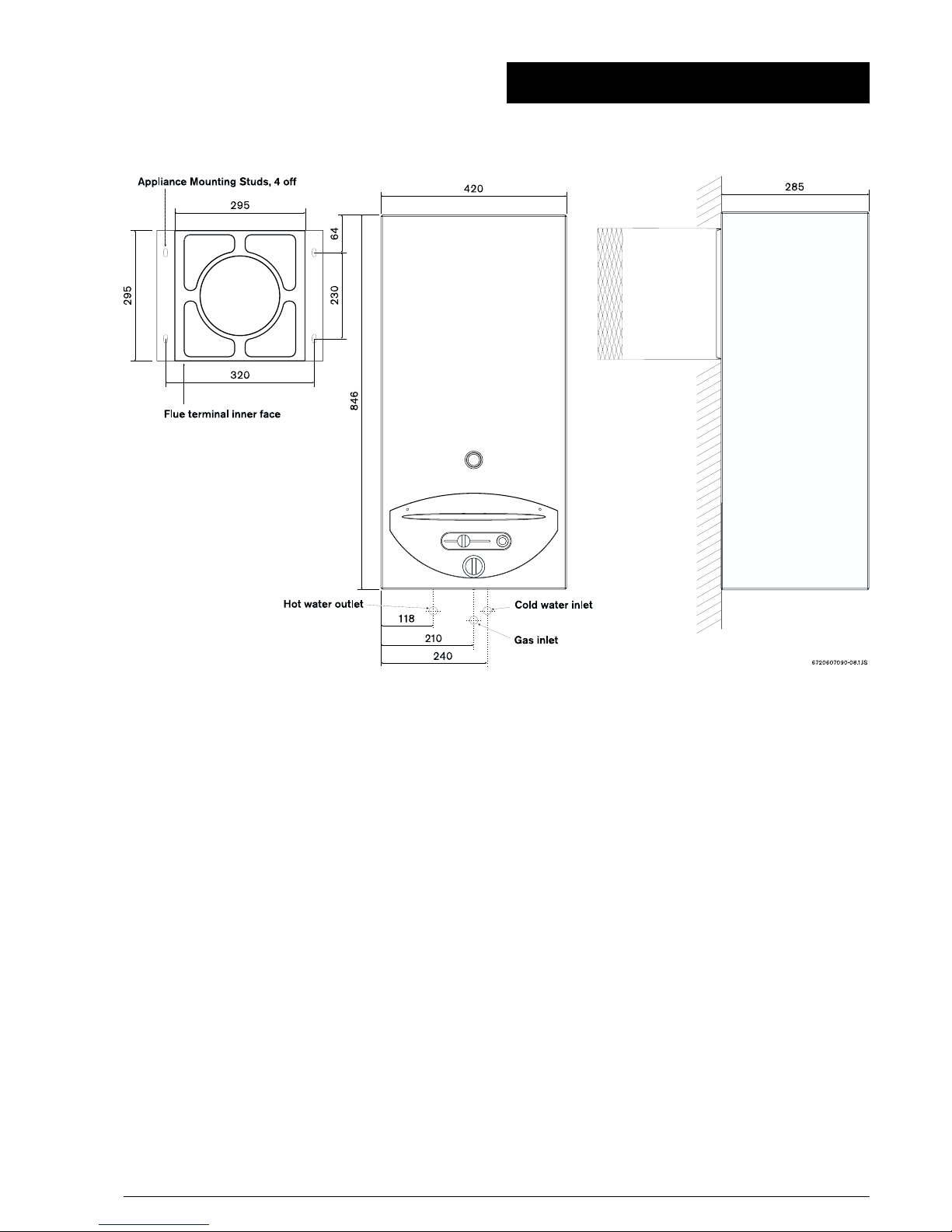
Fig. 8 - Siting o the lue terminal
Fig. 7
Dimension Terminal position Minimum distance
AaDirectly below an opening, air brick, opening windows, etc. 1500 mm
BaAbove an opening, air brick, opening window, etc. 300 mm
CaHorizontally to an opening, air brick, opening window, etc. 600 mm
D Below gutters, soil pipes or drain pipes 300 mm
E Below eaves 300 mm
F Below balconies or car port roof 600 mm
G From a vertical drain pipe or soil pipe 300 mm
H From an internal or external corner 600 mm
I Above ground roof or balcony level 300 mm
J From a surface facing the terminal 600 mm
K From a terminal facing the terminal 600 mm
L From an opening in the car port (e.g. door, window) into the dwelling 1 200 mm
M Vertically from a terminal on the same wall 1 500 mm
N Horizontally from a terminal on the same wall 300 mm
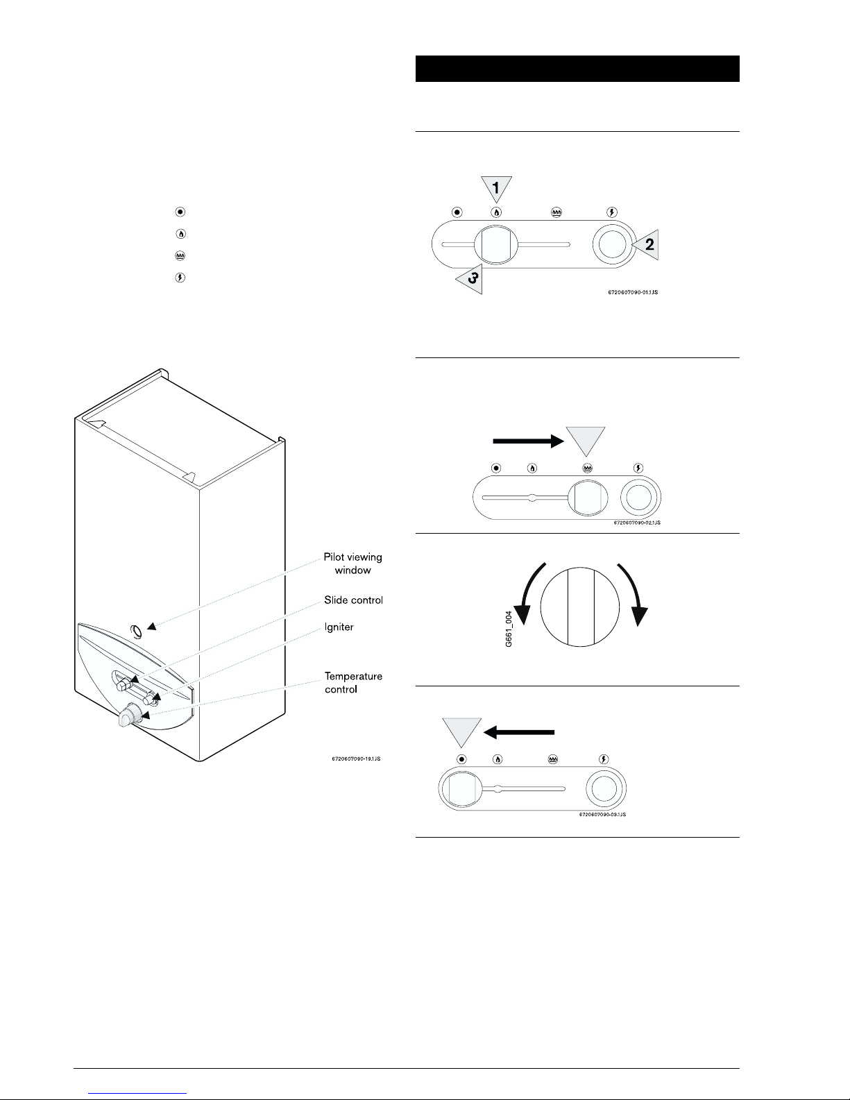
116 720 607 090
9. Air Supply
9.1 The a liance does not require a se arate vent for
combustion air.
9.2 The a liance may be installed in an unvented
com artment.
9.3 There must be sufficient clearance around the
a liance to allow ro er circulation of air. The clearences
required for o eration will normally be adequate.
9.4 Refer to BS 6798 and BS5440:2 for additional
information.
10. Gas Supply
10.1 The gas installation should be in accordance with
BS 6891.
10.2 The connection to the a liance is 15mm
com ression via the gas isolation valve su lied.
10.3 Ensure that the i ework from the meter to the
a liance is of adequate size. If the a liance gas rate cannot
be achieved, the s ecified hot water conditions will not be
reached.
11.1 FLUE INSTALLATION
If an existing flue terminal is not being used, refer to the flue
installation instructions on the wall tem late.
11.2 This a liance is suitable for installation in conjunction
with a “SEDUCT” flue system that com lies with the
requirements of BS 5440 - 1 2000 & IS 813:2002. For
“SEDUCT” installations flue kit art no. 31/12968 and
ilot kit 5113785must be used.
These kit contain instructions referring to installations
with “SEDUCT” flue systems and the a liance
conversion rocedure.
11.3 Un ack the a liance and take care to remove the
installation kit which is acked on to of the olystyrene
acking
The installation kit consists of the following:
Gas inlet:
1x Co er inlet elbow, Com ression Nut, fibre washer
1x Isolation valve, 2 x Com ression nuts and Olives
Water Inlet:
1x Co er inlet elbow, Com ression Nut, fibre washer
1x Isolation valve, 2 x Com ression nuts and Olives
Water Outlet:
1x Flanged Co er Pi e, Com ression nut, Fibre washer
11.4 Lay the a liance on its back and unscrew the
Tem erature Control Knob Bezel.
11. Installation
Fig. 9

12 6 720 607 090
11.5 Unfasten the two retaining screws and lift the case
clear.
11.6 Remove the flue hood from the a liance by undoing
the three fixing screws and lift the hood clear.
11.7 Place the a liance on its side, obtain the flue
terminal sealing stri from the kit and fit into the recess
around the flue a erture in the back of the a liance.
(fig. 10).
11.8 Lift the a liance and locate onto the four flue terminal
mounting studs. Secure in osition using the four slotted
nuts and washers rovided.
11.9 Re-fit the flue hood making sure that the s igot of
the collector hood enters the flue terminal duct. Tighten
the three collector hood fixing screws.
Note: The whole of the gas installation should be ins ected
and tested for soundness and urged in accordance with
the recommendations of BS 6891.
11.10 Make u the gas su ly to the u er connection on
the gas control assembly using the fibre washer rovided.
Fit the gas isolation valve as close as ossible to the
a liance (fig. 11, os. 1).
11.11 Connect the a liance to the incoming cold water
su ly using the co er Inlet Elbow and Isolation Valve.
A fibre washer is rovided (fig. 11, os. 2).
11.12 Connect the a liance to the domestic water remote
draw off oints via the outlet fitting.
11.13 Turn on the water su ly to the a liance. O en the
isolation valve on the inlet fitting to the a liance and
then o en the highest hot water ta in the installation
until all air is removed from the system.
Fig. 10
Fig. 11

136 720 607 090
Fig. 16 - Burner pressure test point
12. Commissioning
Before commissioning the a liance, the gas installation
must be urged and tested for gas soundness in accordance
with BS 6891.
12.1 Ensure that the gas isolation valve in the gas inlet
i e is turned off.
12.2 Loosen screw A and connect a ressure gauge to
the test oint. (fig. 12).
12.3 Turn on the gas isolation valve, re lace the Outer
Case.
12.4 Move the gas control slide to the ignition osition .
(fig. 13).
De ress slide control and hold it in.
Press the igniter re eatedly until the ilot is alight.
Release the slide control a rox 10 seconds after ilot
lights.
Re eat these ste s if the ilot does not remain alight.
Note: On initial light u , or after rolonged shut down,
the establishment of the ilot may take several attem ts
due to the resence of air in the gas su ly i e.
The ilot flame should envelo e a roximately 5 mm of
the thermocou le head.
12.5 Once ilot is established, move slide control to burner
o eration osition . Fully o en any hot water ta . The
main burner should light.
12.6 Check the dynamic inlet gas ressure is 20 mbar.
If the ressure is not correct then check the gas su ly
to the a liance.
If the ressure is correct, turn off the hot water ta and
move the slide to the off osition. (fig. 15).
Remove the outer Case, turn off the Gas Isolation Valve.
Remove the ressure gauge and tighten screw A. (fig.
12).
12.7 The burner ressure is factory set and should not
require adjustment, confirmation of burner ressure can
be made as below.
Loosen screw D and connect the ressure gauge to the
test oint (fig. 16). Re lace the Outer Case.
Re-light the a liance as described in aragra h 12.4
and 12.5.
12.8 O erate the a liance for at least 2 minutes then
check that the burner ressure is 14.1 mbar.
12.9 Turn off the hot water ta . remove the Outer Case.
Close the gas service cock. Remove the ressure gauge
and tighten screw D. Re lace the Outer Case.
12.10 On com letion of the commissioning and testing of
the system, the installer should:
12.10.1 Give the Instructions to the user for safe
kee ing.
12.10.2 Ex lain and demonstrate the lighting and
shutdown rocedures.
12.10.3 Advise the user of the recautions necessary
to revent damage to the system and to the building
in the event of the system remaining ino erative during
frost conditions.
12.10.4 Recommend that the a liance is serviced
annually for reasons of safety and economy and that
the servicing must be carried out by a com etent
erson.
Fig. 12 - Inlet pressure test point
Fig. 13 - Gas control slide - Pilot ignition position
Fig. 14 - Gas control slide - operating position
Fig. 15 - Gas control slide - shut down position
Move slide control to the far left

14 6 720 607 090
13. Inspection and Servicing
For reasons of safety and economy it is recommend that
the a liance is serviced annually. The servicing must be
carried out by a com etent erson.
Before commencing any service o eration turn off the gas
su ly at the main gas service cock. Ensure that the
a liance is cool.
Access or Servicing
Pull off the fascia and undo the two fixing screws.
Pull off the Tem erature Control Knob.
Unscrew Tem erature Control Knob Bezel.
Lift the casing clear. (See fig. 17).
13.1 Heat Exchanger
Remove the flue hood assembly by undoing the three
retaining screws and ulling the hood out of the flue
connector duct.
Ins ect and if necessary clean the heat exchanger
flueways.
13.2 Pilot Assembly
Undo the nuts at both ends of the ilot i e. Withdraw
the ilot i e downward taking care to retain the ilot
injector.
Ins ect the ilot injector.
Check the ilot burner and electrode are clean and
undamaged.
Pull off the ilot filter and clean. (fig. 18).
Clean or re lace com onents if necessary.
Fig. 17 - Access or servicing
Fig. 18

156 720 607 090
13.3 Main Burner
Disconnect the ilot gas i e at the gas valve.
Disconnect the ilot gas i e from the ilot burner and
remove from the a liance com lete with seal. Take care
not to lose the ilot injector.
Remove the two screws retaining the ilot bracket and
lift com lete assembly clear.
Disconnect the union fittings at either end of the ressure
test i e located to the left hand side of the burner.
Remove and retain the fibre washer.
Remove the ressure test i e.
Lift and rotate the front edge of the burner backward
through 180 degrees. With the burner oriented
horizontally and u side down, withdraw forward beneath
the combustion chamber skirt. (fig. 19).
Ins ect and clean the injectors if necessary.
Ins ect and clean the main burner bars if necessary.
13.4 Re-assembling the Appliance
Re-assemble the a liance in reverse order ensuring the
following:
1. The flue hood outlet duct correctly enters the flue
terminal duct and the flue hood is fully seated against
the to of the heat exchanger.
2. The washer in the main gas line union connection
is correctly located.
3. The seals around the igniter cable/thermocou le
and ilot gas i e are correctly seated in the
combustion chamber base and the ilot injector has
been fitted. (fig. 20).
Turn on the gas su ly at the main gas service cock and
check for gas soundness BS 6891 while the a liance
is running.
Re-commission the a liance as detailed in Section 12.
Fig. 19
Fig. 20

16 6 720 607 090
14. Replacement o Parts
Any servicing or arts re lacement must be carried out by a
com etent erson. Use only genuine Manufacturer’s Parts.
Before commencing servicing or arts re lacement turn off
the gas su ly at the main gas isolation valve and ensure
that the a liance is cool.
14.1 Pilot Burner / Injector
Disconnect the ilot gas i e and thermocou le at the
gas valve and ull off the red cable from the igniter unit.
Disconnect the ilot gas i e from the ilot burner and
remove from the a liance com lete with seal.Take care
not to lose the ilot injector. ins ect and re lace the
injector if necessary.
Remove the two screws retaining the ilot bracket and
lift the com lete assembly clear com lete with the red
seal.
Pull off the ilot filter. Undo the screw fixing the s ark
electrode/ thermocou le retaining bar and lift these clear.
Re lace the ilot burner/bracket and re-assemble in
reverse order. (fig. 21).
14.2 Spark Electrode / Thermocouple
Follow the instructions in Section 14.1 and re lace the
faulty com onent.
14.3 Main Burner
Disconnect the ilot gas i e and thermocou le at the
gas valve and ull off the red cable from the igniter unit.
Disconnect the ilot gas i e from the ilot burner and
remove from the a liance with seal. Take care not to
lose the ilot injector.
Remove the two screws retaining the ilot bracket and
lift the com lete assembly clear.
Disconnect the union fittings at either end of the ressure
test i e located to the left hand side of the burner.
Undo the union connection below the burner.
Remove and retain the fibre washer.
Remove the ressure test i e.
Lift and rotate the front edge of the burner backward
through 180 degrees. With the burner oriented
horizontally and u side down, withdraw forward beneath
the combustion chamber skirt.
Re lace the burner and re-assemble in reverse order
taking care that the seals around the igniter cable/
thermocou le and ilot gas i e are correctly seated in
the combustion chamber base and the ilot injector has
been fitted. (fig. 21 and 19).
14.4 Heat Exchanger
Remove the flue hood assembly by undoing the three
retaining screws and ulling the hood out of the flue
terminal duct.
Isolate the a liance from the incoming cold water su ly,
o en a hot ta and drain down the a liance via the
fitted drain cock.
Undo the two retaining screws from the heat exhanger
bracket.
Disconnect the heat exchanger inlet and flow i es at
the base of the combustion chamber.
Remove the locknuts from the heat exchanger inlet and
Fig. 21

176 720 607 090
outlet connections and lift the heat exchanger clear.
Re lace the heat exchanger and re-assemble in reverse
order.
14.5 Igniter Unit
Pull off the two wires from the rear of the unit, unscrew
the lastic retaining nut on the control anel and ush
out the Piezo unit.
Re lace and re-assemble in reverse order. (fig. 22).
14.6 Water Valve
Isolate the a liance from the incoming cold water su ly
and drain down the a liance via the fitted drain cock.
Undo the inlet water connection at the base of the
combustion chamber and at the water valve inlet.
Slacken the two screws between the water valve and
gas valve and ull the water valve clear.
The dia hragm within the valve can be re laced by
removing the five fixing screws holding the valve body
together.
Pull out the water filter fitted into the incoming cold water
ta ing. Clean or re lace as necessary.
Re-assemble in reverse in order. (fig. 22).
14.7 Gas Valve
Remove the water valve as described in Section 14.6.
Disconnect the ilot gas i e and thermocou le from
the gas valve.
Pull off the two cables from the rear of the igniter unit.
Release the main gas i e union connection below the
combustion chamber and lift the valve clear com lete
with the control anel.
Remove the Piezo unit as described in Section 14.5.
Remove the control facia by taking out the four fixing
screws and lifting clear com lete with slider knob.
Prise out the slider bar and remove the two screws
retaining the control frame and lift clear.
Re lace the gas valve and re-assemble in reverse order.
Fig. 22

18 6 720 607 090
15.Fault Finding
16. Short Parts List
Fig. 23
Problem Cause Solution
Incorrect water tem erature. Incorrect gas rate. Check the gas su ly to a liance gas isolation valve.
O en the gas isolation valve.
Check the burner ressure.
Check the inlet ressure.
Water section sticking or faulty. Clean or re lace.
Incorrect water flow rate. Incoming su ly valve closed. O en su ly valve.
Low water ressure. Check the water ressure is above 0.2 bar.
Water section sticking or faulty. Clean or re lace.
Noise. Scale in heat exchanger. Descale and service.
High gas rate. Check the burner ressure.
Low water flow rate. Check the water flow rate.
Pilot flame will not light or stay
lit.
No gas su ly. Connect gas su ly.
Gas isolation valve closed. O en gas isolation valve.
Air in gas line. Purge the line.
Pilot injector blocked. Clean/re lace the injector.
No s ark. Clean or re lace the electrode, Piezo unit or cable.
Main burner will not light. Gas ressure low. Check the inlet and burner ressure.
Gas isolation valve artially closed. O en the gas isolation valve.
Low water rate. Check the water rate.
Water section dia hragm faulty. Re lace the dia hragm.
Gas valve faulty. Re lace the gas valve.
Ex losive ignition. Reduced ilot flame. Clean or re lace the ilot injector assembly.
Faulty slow ignition valve. Re lace the slow ignition valve.
Description Part Number
1Knob and Bezel 5 110 844
2Pilot Burner (75) 5 110 880
Pilot Burner (Se-duct installation) 5 113 993
3Pilot Injector (5) 5 110 884
Pilot Injector (Se-duct installation) 5 113 787
4Thermocou le 5 110 886
5Gas Valve 5 110 894
6Water valve 5 110 959
7Dia hragm (F) 5 110 963
8Piezo Igniter 5 110 953
9S ark Electrode 5 110 956

196 720 607 090
17. Notes

GENERAL ENQUIRIES (GB)
08706 060 780
TECHNICAL (GB)
08706 049 049
SERVICE (GB)
08706 096 096
LITERATURE REQUEST (GB)
08706 060 623
TECHNICAL (IE)
1850 560 570
Comp No 5111036 – Iss 2 – 10 / 04
Baxi Potterton
A Trading Division of Baxi Heating U.K. Ltd
Brownedge Road Bamber Bridge Preston Lancashire PR5 6SN
www.baxi otterton.co.uk
This manual suits for next models
1
Table of contents
Other Main Water Heater manuals
Popular Water Heater manuals by other brands

Siemens
Siemens 9001042052 Installation and operating instructions

STIEBEL ELTRON
STIEBEL ELTRON SHC 10 Operation and installation

Maytag
Maytag Series Six user guide

Takagi
Takagi T-K4U-IN Installation manual and owner's guide

Noritz
Noritz NC199-DVC-CA installation manual

Bosch
Bosch C1210ES Technical service bulletin