MIGE1203 Series Industrial Gigabit Media Converter/MIGE2205G Series
Industrial Ethernet Switch
Introduction
1. Product outline
1.1. Product Introduction
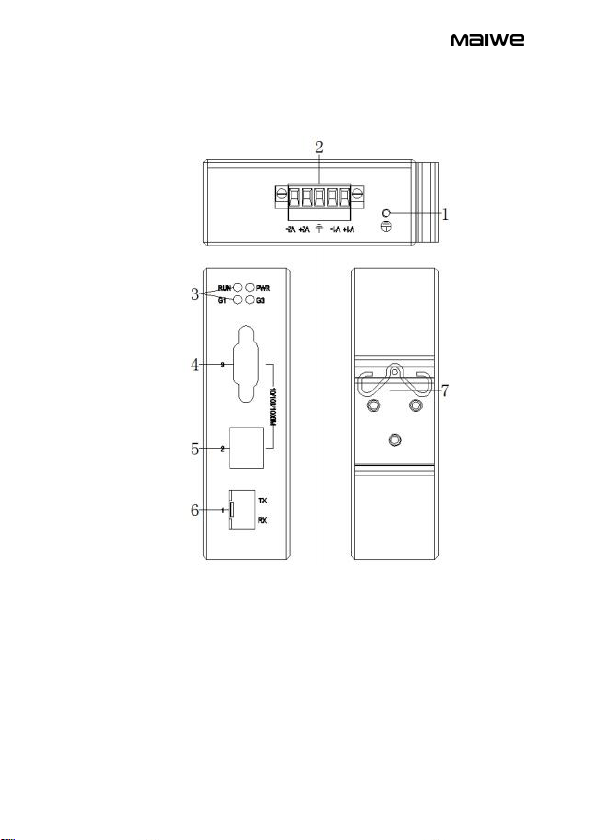
MIGE1203G-GS/M and MIGE1203G-GS/M-DB9 are 2 10/100/1
000Base-T port and 1 1000Base-X optical fiber interface adaptive
industrial-grade Ethernet Optical fiber transceiver which applied to the optical
fiber remote transmission of Ethernet signal.
MIGE2205G is 5 10/100/1000Base-T port adaptive high performance
industrial Ethernet switch. MIGE2205-GS/M is 4 10/100/1000Base-T port and
1 adaptive industrial Ethernet switch with 1000Base-X optical fiber
interface.One interface of MIGE1203G-GS/M-DB9 is a DB9 port.Other models
are all RJ45 ports, and each has an adaptive function, automatically configure
set to 10/100/1000Base-T state and full-duplex or half-duplex operation mode
and connect MDI/MDI-X. This product uses standard 35mm pitch DIN card and
the rail-mounted installation method is very suitable for installation applications
on industrial sites.
1.2. Features
1.2.1. High-performance Ethernet switch interface:
Data Store and Forward method
10/100/1000Base-T adaptive Ethernet electrical interface, of which
10/100Base-T support full-duplex or half-duplex mode, 1000Base-T supports
full-duplex mode
1000Base-X optical fiber interface, the interface is a shielded SFP base
Compliant IEEE802.3, IEEE802.3u, IEEE802.3ab, IEEE802.z,
IEEE802.3x
Lightning protection standard 10/700us: CM 6kV-150A and DM 2kV-50A
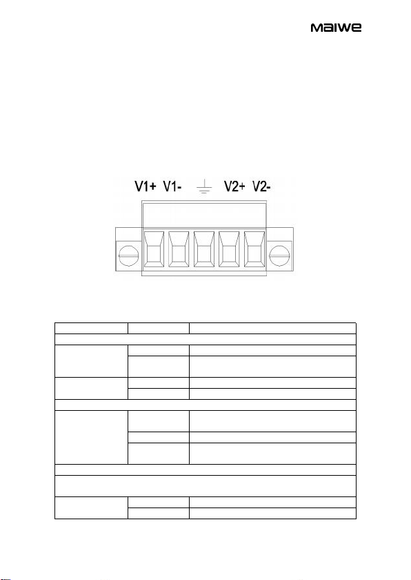
1.2.2. Industrial grade power supply design
Power range:
AC model AC85-264V or DC110-370V
DC standard model DC12-48V, optional DC48V (36-72V)
Electrical surge, overcurrent, anti-reverse protection and excellent EMC
performance
Environmental materials ,5.08mm pitch and easy to access power
terminals
1.2.3. Solid exterior design
Single-rib aluminum chassis design with heat dissipation surface, no fan