Major M-360 User manual

M-360
INSTRUCTION MANUAL
AM / FM / SSB
120 CHANNEL
DIGITAL PLL SYNTHESIZED
TRANSCIEVER

Sensitivity
·[AM] 1 µV at 10dB S/N
·[FM] 0.5 µV at 20 dB S/N
·[SSB] 0.5 µV at 10 dB S/N
Spurious rejection ratio: 40dB
Squelch Sensitivity at
Maximum [AM/FM]: 300 µV
Squelch Sensitivity at
Maximum [SSB] 300 µV
Squelch Sensitivity at
Threshold [AM/FM]: 1 µV
Squelch Sensitivity at
Threshold [SSB]: 0.7 µV
A.G.C. (As measured to
EIA specs): 70 dB
IF response at 6 dB down
bandwidth [AM/FM]: 6 kHz
IF response at 6 dB down
bandwidth [SSB]: 2 kHz
Adjacent Channel
Selectivity: 40 dB
Adjacent Channel
Selectivity: 40 dB
Frequency Stability: ±0.005%
Audio Output Power at
Maximum [8 Ohm]: 4W
Audio Output Power at
10% distortion [8 Ohm]: 3W
Audio Fidelity at
3,000 Hz: -15 dB
S-Meter Sensitivity for S-9: 100µV
Current Drain at no signal: 350 mA
Current Drain at Maximum
Audio Output: 1500mA
Receiver
Specifications
RF Output Power at 13.8V DC
[SSB] 20W PEP nominal
[AM/FM] 10W nominal
Modulation Capability
[AM]: 100% Down
Frequency Stability: ±0.005%
SSB Generation: Double balanced
Modulator with
Crystal lattice filter
Carrier Suppression [SSB]: 40dB down
Unwanted Sideband
Suppression [SSB]: 60dB down
Harmonic Suppression: 60dB down
FM Deviation with 20 mV
1260 Hz audio: 1.5 kHz
Current Drain at no
Modulation: 1850 mA [AM]
800 mA [SSB]
Current Drain at Maximum
Modulation: 2.4 A [AM]
Transmitter
- 1 -
Microphone wiring
Microphone connection for Major M360 (Viewed from Solder Side of the plug)
TX
Transmit
RX
Receive
COM
Common
/ Screen
AUD
Mic. Audio

Installation Instructions
- 2 -
This transceiver is designed for 12 volt DC operation with either a negative or positive ground system. In
order to install the radio, it is important to know whether your vehicle has a positive or negative ground
system. Connecting the radio incorrectly will damage it.
Vehicle's Electrical System
We suggest that you check with qualified technician and find out if your make and model vehicle uses a
positive ground or negative ground system.
Location
Mount the radio so that all controls are within easy reach of the operator. Avoid mounting it directly in
front of air conditioning or heater ducts. Be sure it does not interfere with the operation of the vehicle, or
any equipment in the vehicle. Your CB Radio could be installed inside your glove compartment if desired.
Most often, CB equipment is mounted under the dash within easy reach of the driver. If under-the-dash
mounting is impractical, consider mounting the unit on the transmission hump in the centre of the
floorboard. Disconnecting the battery will prevent short-circuits, blown fuses, and other potential hazards
and inconveniences. Reconnect the battery only after the radio and antenna have been installed and all
electrical connections completed.
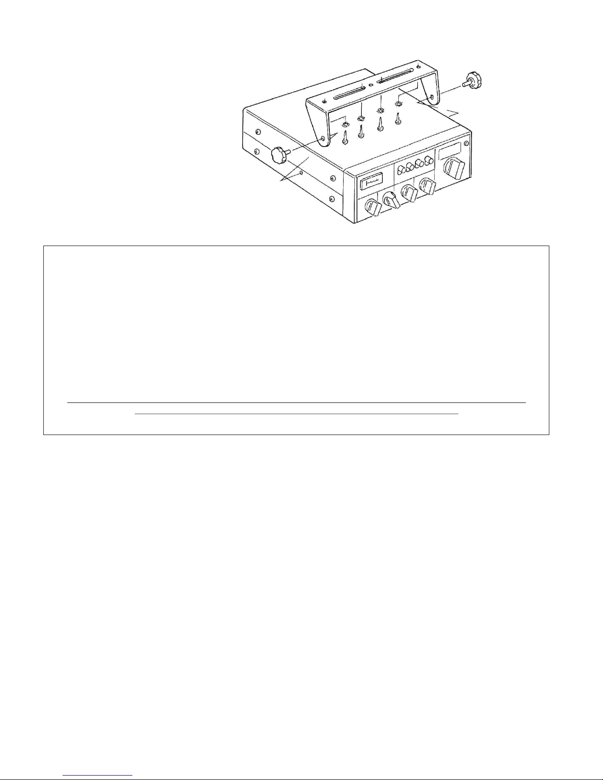
Mounting The Radio
Locate the mounting bracket and hardware furnished with the radio. Remove the bracket from the unit,
and hold the bracket up to the mounting location you have selected. Take a soft lead pencil and draw an
outline of the entire bracket, including the holes for drilling, on the place it is to be mounted. Do not drill
any holes yet. Before you drill, look behind the place that you have chosen to mount your unit to make
sure that there are no wires or other items that can be damaged by the drill bit. Drilling without a
thorough check can result in damage to the electrical system or other parts of your car or truck.
If the area is clear, take a centre punch and make a small indentation in each of the places marked for
drilling. Using the centre punch first will keep the drill from sliding and damaging the upholstery or
surface of the dash.
Use a #30 (1/8 inch) drill bit for the self threading screws. Wrap tape around the bit about one inch from
the point. The tape will prevent the bit from entering too far into the hole and damaging objects behind
the hole. Place the drill bit in the indentations made by the centre punch and drill slowly, being careful
not to damage the surface or make the hole larger than necessary. Protect your eyes with goggles. If you
are drilling through heavy upholstery or carpeting, mark an 'X' exactly at the spot for the hole. Cut the
upholstery or carpeting material alongthe lines of the X with a sharp knife. Peel the corner back so that
while you are drilling, the drill does not catch on the material and unravel it. Once you have drilled the
necessary holes, use the hardware to mount the bracket firmly to the mounting location, then install the
radio in the bracket. Mount the microphone holder to the radio's mounting bracket or to the dash. Before
drilling a mounting hole, be certain that the area behind the mounting position is free of wires and
equipment.
Connecting to a Negative Ground System
Follow these instructions if you are certain that your vehicle has a negative ground system. Connect the
negative (black or green) wire to a screw or bolt on the metal frame supporting the instrument panel, or
to any metal point that is part of the vehicle's metal structure. Remove any paint or coating from under
the screw or bolt to ensure good electrical contact.
If you want your radio to operate at all times without having the ignition switch turned on, connect the
positive (red) wire to the INTERIOR LAMP terminal on the vehicle's fuse panel. If you want your radio to
operate only when the ignition switch is turned on, connect the positive (red) wire to the RADIO terminal
on the vehicle's fuse panel.
Do not turn on the CB radio until the antenna is connected. If you attempt to transmit without the
antenna connected, you risk burning out the unit's power transistors.

- 3 -
Typical Under-dash installation
Connecting to a Positive Ground System
Follow the instructions in this section only if you are certain that your vehicle has a positive ground
system. Connect the positive (red) wire to a screw or bolt on the metal frame supporting the
instrument panel, or to any metal point that is part of the Vehicle's metal structure. Remove any
paint or coating from under the screw or bolt to ensure good electrical contact.
If you want your radio to operate at all time without having the ignition switch turned on, connect the
negative (black or green) wire to the INTERIOR LAMP terminal on the vehicle's fuse panel. If you
want your radio to operate only when the ignition switch is turned on, connect the negative (black)
wire to the RADIO terminal on the vehicle's fuse panel.
Do not turn on the CB radio until the antenna is connected. If you attempt to transmit without the
antenna connected, you risk burning out the unit's power transistors.
Antennas
The antenna's mounted location on the vehicle affects the operation of the CB radio. Transmission and
reception characteristics vary for different antenna locations.
Ideally, the transmitted power and receiving sensitivity should be uniform in all directions, regardless of
which direction the vehicle faces.
In a typical installation however, the vehicle's irregular shape produces some cancellation effects which
prevent ideal performance. However, an antenna located near the center of the vehicle's roof will provide
performance closest to ideal. A compromise between such factors as the cost of the antenna, the ease and
personal preference of installation, and uniformity of the desired transmission/reception characteristics will
determine the best mounting location.

- 4 -
To Receive
1 Turn the unit on by rotating the Volume control clockwise. Continue to rotate the knob in the same
direction to increase the loudness.
2 Turn the Squelch control anti-clockwise, then slowly clockwise until the hissing sounds just stop. It is
important to set this control carefully. When properly set, annoying static noise (hiss) will be eliminated
while allowing reception of weak signals. Turning the Squelch control too far clockwise increases the
signal required to actuate the receiver and may prevent reception of weaker signals. Turning the control
too far anti-clockwise will allow the receiver to pick-up atmospheric noise and objectionable background
hiss.
3 Select the required frequency band using the Hi-Lo Switches (See “Controls and Functions” for
details).:
4 Turn the channel selector to any the forty channels.
5 Set the Mode switch to “AM”, “FM”, “LSB” or “USB”.
NOTE: When using the UK FM (CB 27/81) Band, the Mode must be set to “FM”.
When using LSB and USB, adjust the Clarifier to obtain the most pleasing (normal) range of voice tones.
Varying this control to either extreme varies the tone of the voice from a high pitch to a barely
intelligible low tone.
To Transmit
1. Plug the microphone cord into the MIC jack.
2. Wait until the channel you selected is clear.
3. Hold the microphone directly in front of you at a distance, of 2 or 3 inches. Press the microphone's
pushbutton and talk in a normal voice to transmit your message.
Note: To avoid garbled transmissions, do not shout into the microphone or hold the mic too close to
your mouth.
Release the microphone's pushbutton to receive.
Operating Instructions

- 5 -
1
3
4 5 2
2)
5
5 4
54
54
2
6
7
S-RF Power Meter
This meter shows the relative strength of incoming signals when receiving, and RF power output when
transmitting.
Loc-Dx Switch
The Loc-Dx switch operates an RF Gain function to reduce reception of weaker signals. For normal
operation, set the switch to the DX (up position). If the signal is too strong, distortion may result, in
which case set the switch to the LOC (down position).
Frequency Selection Switches
For all normal Channels ensure the “Uk40” ( switch is set to “Off”
- For MID Band (26.965 27.405)
- “Hi Band - Lo Band” switch ( ) to “Lo Band”
- For HIGH Band (27.415 27.855)
- Set “Hi Band - Lo Band” ( ) to “Hi Band” AND set the “Hi - Lo” switch ( ) to “Lo”
- For HIGH-HIGH Band (27.865 28.305)
- Set “Hi Band - Lo Band” ( ) to “Hi Band” AND set the “Hi - Lo” switch ( ) to “Hi”
- For UK FM (CB 27/81) Band (27.60125 27.99125)
- Set “Hi Band - Lo Band” ( ) to “Hi Band” AND set the “Hi - Lo” switch ( ) to “Lo”
- AND - Ensure the “UK40-Off” ( ) switch is set to “UK 40”
Channel Display
Shows current selected Channel
TX Indicator
Illumination of the TX indicator shows that your CB unit is transmitting.
Controls and Functions
88
HI HI BAND
UK 40
LO BANDLO
LOC
OFF
DX
HI
SQUELCHCLARIFIER VOLUME
LSB FM
USB AM
OFF
PA
SIGNAL
1 3 5 7 9
AM/FM/SSB
M 360
.
.
.
.
.
.
.
.
.
.
.
.
.
.
.
.
.
.
.
.
.
.
.
.
.
1234567
8910 11 12 13

- 6 -
8
9
11
10
12
13
Clarifier
The Clarifier adjusts the frequencies of the Transmitter and receiver very slightly in order to ensure
that Sideband [USB or LSB] signals are heard correctly. When using LSB and USB, adjust the Clarifier
to obtain the most pleasing (normal) range of voice tones. Varying this control to either extreme
varies the tone of the voice from a high pitch to a barely intelligible low tone.
Mode switch
Rotate to select to “AM”, “FM”, “LSB” or “USB”.
NOTE: When using the UK FM (CB 27/81) Band, the Mode must be set to “FM”.
Squelch
The squelch function cuts-off all signals to the receiver at a variable level and is used to silence
background noise, static or distant stations. Rotate the Squelch control Clockwise until the desired
level is reached.
PA
Rotating the squelch control fully anti-clockwise engages the PA Function. To use the PA press the PTT
button on the microphone. Adjust the output volume using the Volume knob.
NOTE: Always ensure a PA Horn or suitable speaker is connected to the CB before using this function.
Volume
The Volume control determines the volume that the received signal is heard (or, if PA is in use, the
output volume). Rotate the control Clockwise to increase Volume. Rotate Anti-clockwise to decrease,
and fully anti-clockwise to switch the CB Off.
Channel selection Rotary Switch.
Rotate to select any of the forty channels within each Band.
Note: The Volume, Squelch, Clarifier, and Loc-Dx, controls are inoperative when transmitting.
Controls and Functions (Cont’d)
88
HI HI BAND
UK 40
LO BANDLO
LOC
OFF
DX
HI
SQUELCHCLARIFIER VOLUME
LSB FM
USB AM
OFF
PA
SIGNAL
1 3 5 7 9
AM/FM/SSB
M 360
.
.
.
.
.
.
.
.
.
.
.
.
.
.
.
.
.
.
.
.
.
.
.
.
.
1234567
8910 11 12 13

27.865
27.875
27.885
27.905
27.915
27.925
27.935
27.955
27.965
27.975
27.985
28.005
28.015
28.025
28.035
28.055
28.065
28.075
28.085
28.105
28.115
28.125
28.155
28.135
28.145
28.165
28.175
28.185
28.195
28.205
28.215
28.225
28.235
28.245
28.255
28.265
28.275
28.285
28.295
28.305
1
2
3
4
5
6
7
8
9
0
11
12
13
14
15
16
17
18
19
20
21
22
23
24
25
26
27
28
29
30
31
32
33
34
35
36
37
38
39
40
27.415
27.425
27.435
27.455
27.465
27.475
27.485
27.505
27.515
27.525
27.535
27.555
27.565
27.575
27.585
27.605
27.615
27.625
27.635
27.655
27.665
27.675
27.705
27.685
27.695
27.715
27.725
27.735
27.745
27.755
27.765
27.775
27.785
27.795
27.805
27.815
27.825
27.835
27.845
27.855
1
2
3
4
5
6
7
8
9
0
11
12
13
14
15
16
17
18
19
20
21
22
23
24
25
26
27
28
29
30
31
32
33
34
35
36
37
38
39
40
26.965
26.975
26.985
27.005
27.015
27.025
27.035
27.055
27.065
27.075
27.085
27.105
27.115
27.125
27.135
27.155
27.165
27.175
27.185
27.205
27.215
27.225
27.255
27.235
27.245
27.265
27.275
27.285
27.295
27.305
27.315
27.325
27.335
27.345
27.355
27.365
27.375
27.385
27.395
27.405
1
2
3
4
5
6
7
8
9
0
11
12
13
14
15
16
17
18
19
20
21
22
23
24
25
26
27
28
29
30
31
32
33
34
35
36
37
38
39
40
27.60125
27.61125
27.62125
27.63125
27.64125
27.65125
27.66125
27.67125
27.68125
27.69125
27.70125
27.71125
27.72125
27.73125
27.74125
27.75125
27.76125
27.77125
27.78125
27.79125
27.80125
27.81125
27.82125
27.83125
27.84125
27.85125
27.86125
27.87125
27.88125
27.89125
27.90125
27.91125
27.92125
27.93125
27.94125
27.95125
27.96125
27.97125
27.98125
27.99125
1
2
3
4
5
6
7
8
9
0
11
12
13
14
15
16
17
18
19
20
21
22
23
24
25
26
27
28
29
30
31
32
33
34
35
36
37
38
39
40
“UK 40”
“HI BAND” + “LO”
“HI BAND”
“LO”
“HI BAND”
“HI”
“LO BAND”
“LO” or “HI”
“Mids”
CEPT Std.
“Highs”
‘Freeband’ 27.555
“UK CB FM”
‘Muppet’ Band.
Operating Frequencies
Table of contents
Other Major Transceiver manuals
Popular Transceiver manuals by other brands

Kenwood
Kenwood TK-2180 instruction manual

Standard Horizon
Standard Horizon HX751 Service manual

FlexRadio Systems
FlexRadio Systems FLEX-6000 Signature Series Hardware reference manual

TIL
TIL -92-SC TSC-4100 Installation and operating instructions

Kenwood
Kenwood TK-90 instruction manual

Technisonic Industries Limited
Technisonic Industries Limited TDFM-136B Quick reference guide