Maker Factory 1968203 User manual

ALTER
8+
ELEKTRONIK ADVENTSKALENDER FÜR KIDS
ELECTRONIC ADVENT CALENDAR FOR KIDS
CALENDRIER ÉLECTRONIQUE DE L'AVENT POUR ENFANTS
ELEKTRONISCHE ADVENTSKALENDER VOOR KINDEREN
CALENDARIO DELL'AVVENTO ELETTRONICO PER KIDS
ELEKTRONICZNY KALENDARZ ADWENTOWY DLA DZIECI
ELEKTRONIK ADVENTSKALENDER FÜR KIDS
ELECTRONIC ADVENT CALENDAR FOR KIDS
CALENDRIER ÉLECTRONIQUE DE L'AVENT POUR ENFANTS
ELEKTRONISCHE ADVENTSKALENDER VOOR KINDEREN
CALENDARIO DELL'AVVENTO ELETTRONICO PER KIDS
ELEKTRONICZNY KALENDARZ ADWENTOWY DLA DZIECI
ELEKTRONIK ADVENTSKALENDER FÜR KIDS
ELECTRONIC ADVENT CALENDAR FOR KIDS
CALENDRIER ÉLECTRONIQUE DE L'AVENT POUR ENFANTS
ELEKTRONISCHE ADVENTSKALENDER VOOR KINDEREN
CALENDARIO DELL'AVVENTO ELETTRONICO PER KIDS
ELEKTRONICZNY KALENDARZ ADWENTOWY DLA DZIECI
ELEKTRONIK ADVENTSKALENDER FÜR KIDS
ELECTRONIC ADVENT CALENDAR FOR KIDS
CALENDRIER ÉLECTRONIQUE DE L'AVENT POUR ENFANTS
ELEKTRONISCHE ADVENTSKALENDER VOOR KINDEREN
CALENDARIO DELL'AVVENTO ELETTRONICO PER KIDS
ELEKTRONICZNY KALENDARZ ADWENTOWY DLA DZIECI
ELEKTRONIK ADVENTSKALENDER FÜR KIDS
ELECTRONIC ADVENT CALENDAR FOR KIDS
CALENDRIER ÉLECTRONIQUE DE L'AVENT POUR ENFANTS
ELEKTRONISCHE ADVENTSKALENDER VOOR KINDEREN
CALENDARIO DELL'AVVENTO ELETTRONICO PER KIDS
ELEKTRONICZNY KALENDARZ ADWENTOWY DLA DZIECI
24 thrilling experiments
24 projets passionnants
24 boeiende projecten:
24 progetti entusiasmanti
24 fascynujące projekty

Imprint
© 2019 Franzis Verlag GmbH, Richard-Reitzner-Allee 2,
85540 Haar bei München •www.franzis.de
Author: Burkhard Kainka
Idea/concept: Michael Büge, Burkhard Kainka
Copy editor: Richard Korff Schmising
Art & design cover: www.ideehochzwei.de
Layout & composition: Nelli Ferderer •nelli@ferderer.de
ISBN 978-3-645-15062-2
2019/01
Picture credits
Drawings created with http://fritzing.org/
All rights reserved, including the rights for photomechanical reproduction and storage
of electronic media. The preparation of distribution of copies on paper, on data carriers
or online, especially as PDF, is only allowed with the explicit permission of the publisher
and will be prosecuted otherwise.
Most product and company names as well as company logos included in this work are
generally also registered trademarks and must be treated as such. For product names,
the publisher generally follows the manufacturer’s spelling.
All projects and experiments presented in this book were developed, reviewed and
tested with the greatest possible care. However, errors in this book cannot be com-
pletely excluded. The publisher and the author are liable for cases of intention or gross
negligence, according to the legal provisions.
Moreover, the publisher and the author are also liable in accordance with the product
liability law in case of damage to life, body or health or in case of culpable violations
of the contract. The damage claim related to considerable violations of the contract is
limited to damage typical for the contract unless a case of mandatory liability accord-
ing to the product liability law applies.
This product was made in accordance with the applicable European directives
and, therefore, carries the CE certificate. The intended use is described in the
enclosed instructions. You are solely responsible for adherence to applicable regulations
in case of any other use or modification of the product. Therefore, construct the experi-
ments exactly as it is described in the instructions. The product must only be passed on
together with the instructions and this notice.
The symbol of the crossed-out rubbish bin indicates that this product must be
recycled as electronic waste separately from household waste. Your local coun-
cil can provide you with information about the nearest recycling point.

Safety instructions
Not suitable for children under 3 years. There
is a risk of suffocation due to small parts being
swallowed or inhaled.
Caution!
Only suitable for children of 8 years or
older. Instructions for parents and other
guardians are enclosed and must be
followed. Packaging and instructions
must be kept as they contain important
information.
Caution!
Avoid short circuits! A direct connection between negative and positive terminals must be
avoided at all costs, because wires and batteries can become hot and the batteries then
discharge quickly. In extreme cases, wires can become glowing hot and the battery can
explode. There is a risk of fire and injury. Point out these dangers to your children and
supervise the experiments. If possible, use only normal zinc-carbon batteries (6F20), which
provide a lower short-circuit current and are therefore less dangerous than alkaline batteries
(6RL61). Never use rechargeable batteries!
Caution!
Eye protection and LEDs: Do not look directly into
an LED from a short distance as this can cause
damage to the retina!
Eye protection and LEDs: Do not look directly
into an LED from a close distance, because a
direct look can cause retinal damage! This is
especially true for bright LEDs in clear housings
and especially for power LEDs. With white,
blue, violet and ultraviolet LEDs, the apparent
brightness gives a false impression of the actual
danger to your eyes. Special care should be
taken when using converging lenses. Operate
the LEDs as described in the manual, but not with
larger currents.
Caution!
Do not carry out experiments on
sockets! The 230 volts of the
power supply are life-threatening!
All experiments in this experiment
package may only be carried out
with the safe battery voltage of 9
volts. Then there is no danger of
touching electrically conductive
parts.
Please instruct your child clearly
that they must read all instructions
and safety instructions and to keep
them near for reference. Notes
and instructions concerning the
assembly of the projects must
always be followed.
Caution!
Risk of injury! There is a risk of injury when using
tools and working with wood, metal and plastic.
Take the age and experience of your child into
account. Help with difficult or dangerous work steps.
Check the safety of the toys you build yourself and
be aware of the risk of injury from sharp edges when
playing. If necessary, rework, file off sharp edges
and deburr holes or cut edges.
Caution!
for parents and children

Children’s electronic calendar 2019
LEDs, transistors and the piezo transducer
Dear children,
Running up to Christmas there are 24 electronic projects waiting for you. The focus is on transistors, light emitting diodes,
a light sensor and a small speaker. You can build completely different things with these components. There is much to
see, to hear and to experiment! And if you want, you can find the information you need here to learn more about how
everything works.
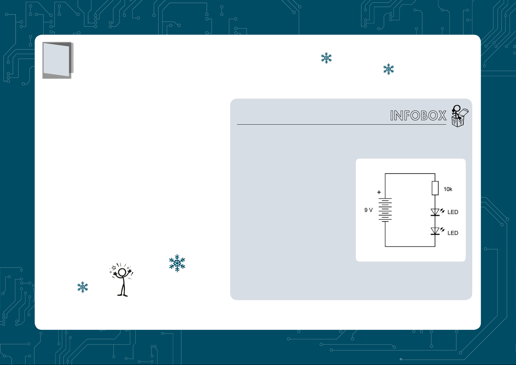
Self-constructed red LED light
Behind the first door of your calendar you
will find six components, so you can start
right away. There are four things needed
in each experiment: a plug-in board, a
battery clip, a switch and a fuse. For the first
experiment, there is also a resistor and a
light-emitting diode (LED).
The battery cable must be fastened as firmly
as possible so that it does not come loose
during the many subsequent experiments.
The exposed ends of the red and black
cables must be plugged into exactly the right
contact holes on the PCB. But first make
small holes with a needle in the protective
foil on the back of the plate and insert the
cables from below. This prevents them from
slipping easily.
The switch and fuse should be placed
exactly in the position as shown. This
then applies to all other experiments until
Christmas. This will prevent big mistakes
from occurring. The resistor and LED are
part of the first experiment. Make sure the
LED is installed the right way around. It
1

has a shorter wire (cathode = negative pole) and a
longer wire (anode = positive pole). Inside you can
see a slightly larger holder on the minus side, which
carries the actual LED crystal.
Once you have finished setting up, compare your
construction with the assembly picture. It’s a good idea to get
help from an adult who checks the first experiment again. In the
following projects, only a few modifications are carried out, so that it
becomes easier and easier.
Now the battery is connected for the first time. Your red LED light
with switch is now ready. Slide the left switch to the ON position and
your red LED will shine. If it doesn’t work, check once more. The
most common mistake is that the LED is installed the wrong way
around. But don’t be afraid, nothing will break. If used the right way
around, it works.
Circuit diagrams
The circuit diagrams in this manual do not
necessarily have to be observed in order to
set up the experiments successfully. But they
can help you understand everything better.
A circuit diagram shows the connections
of the parts in a simplified way with circuit
symbols for each part. Once you get used
to it, a circuit diagram will make it much
easier to understand how everything fits
together.
The battery consists of six battery cells of
1.5 V each. The longer line stands for the
plus pole. The fuse is drawn as a box with
a wire. The switch just shows an open
connection. The resistor is displayed as
a box. And the LED contains a triangle
that represents the current direction. Two
small arrows point to the light generated.
In this diagram you can easily see that all
components form a closed path. It’s called
a circuit. The path is only interrupted at one
point - at the switch that is just opened.
Attention! Never connect an LED directly
to a battery without a resistor. Without the
resistor the current would be too high, and
the LED would be destroyed.
Attention!

Secret light signals
2
Behind door number 2 you will find a push-
button switch with four connection pins.
Install it in the circuit so that it turns on the
power as soon as you press the button. Two
of the connections are connected inside.
If you have installed the push button the
wrong way around, the power will always be
on. When the LED lights up as soon as you
press the button, it is correctly installed. Use
the light button for Morse messages or for
secret signs that no one else knows.
The inner workings of a push-button
Inside the push-button switch there is a slightly upward curved sheet
which is pressed into place by pressing the button. At a certain force, it
clicks, and the sheet metal bulges downwards. It touches the contact in
the middle and thus closes the circuit.
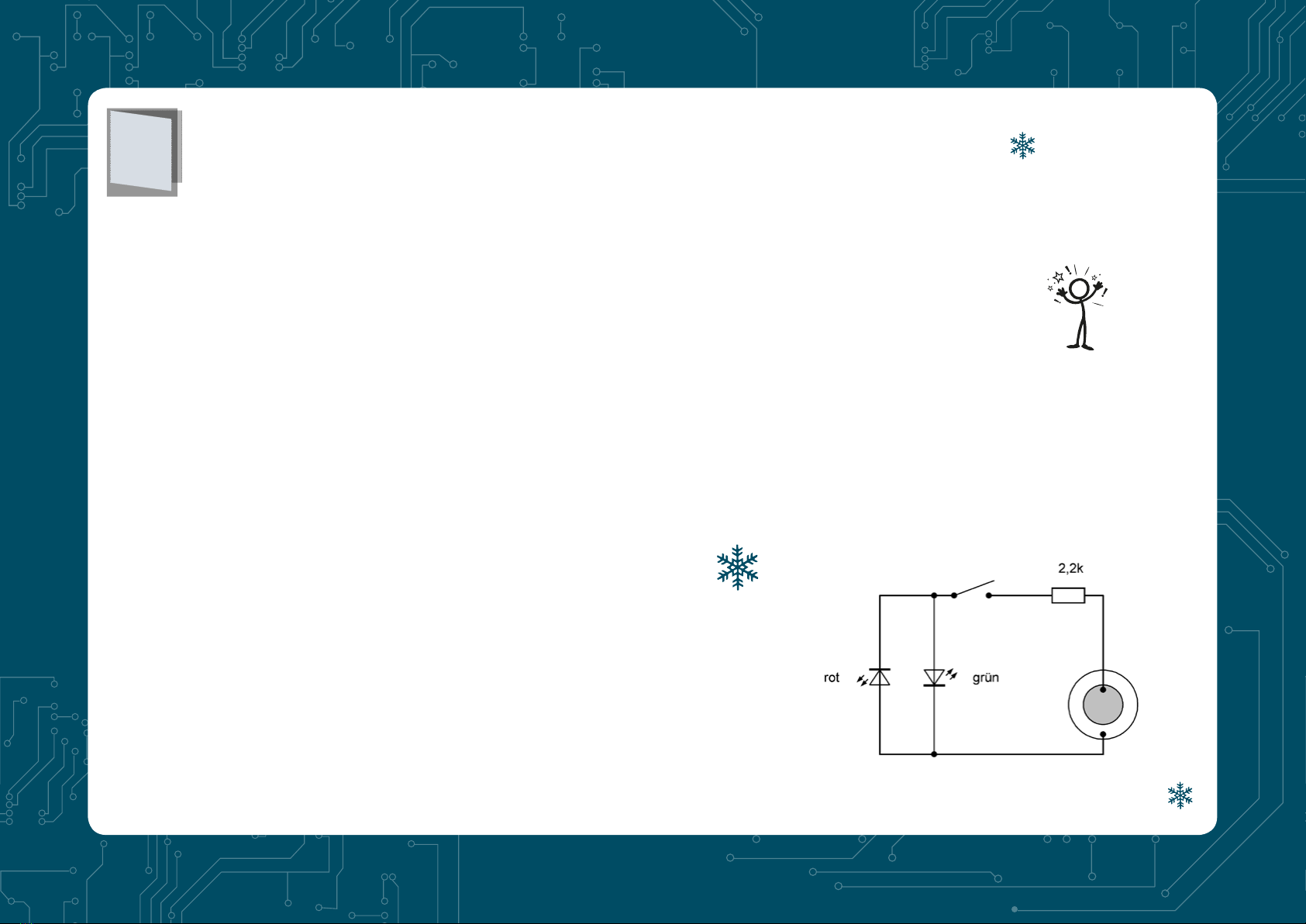
Red and green
Series connection
In series connection, the same current
flows through two or more users. It’s an
“unbranched circuit” because the current
runs in only one way. This means that the
amperage is the same at every point. You
can try this yourself by swapping both LEDs.
The brightness remains exactly the same.
The battery voltage of 9 V is divided
between three users. The red LED has 1.8 V,
the green LED has 2.2 V, and the resistor has
5 V. If all partial voltages are added up, we
get a total voltage of:
1.8 V + 2.2 V + 5.0 V = 9.0 V
3
Behind door number 3 you will find a green LED. Integrate them
into the circuit as shown in the picture. Then both LEDs will shine
together, the red one and the green one. And switch 1 can switch
both on and off at the same time.
A simplified circuit diagram of a series connection
Green turned off
Resistors and their colour rings
The coloured rings on the resistors
stand for numbers. They are read
one after the other, starting at the
ring closest to the edge of the
resistors. The first two rings stand
for two digits, the third for added
zeros. Together they denote the
resistance in ohms. A fourth ring
indicates the accuracy. All resistors
in this calendar have a gold ring.
This means that the value can be
5% higher or lower than indicated
by the coloured rings. Your first
resistance is read like this:
Brown = 1, black = 0,
orange = 000, together 10,000 Ω
(Ohm), i.e. 10 kΩ(Kiloohm).
The resistance colour code
Colour Ring 1
1st digit
Ring 2
2nd digit
Ring 3
Multiplier
Ring 4
Tolerance
black 0 1
brown 1 1 10 1 %
red 2 2 100 2 %
orange 3 3 1000
yellow 4 4 10000
green 5 5 100000 0,5 %
blue 6 6 1000000
violet 7 7 10000000
grey 8 8
white 9 9
gold 0,1 5 %
silver 0,01 10 %
4
Open the 4th door and remove the cable with two plugs. If you
install it along with the push button as shown in the picture, you
can switch off the green LED by pressing the button. If the button
is closed, you have built a by-pass for the electric current. The
current then no longer flows through the green LED, but through
the switch. The green LED goes off, but the red LED becomes a little
brighter at this moment.
In fact, the switch briefly closes
the green LED. This type of short-
circuit is permitted only because the
resistance in the circuit keeps the
current sufficiently low. However, a
direct short circuit of the battery in
the form of a connection between the
positive and negative poles must be
avoided at all costs!

Colour selector
Behind door number 5 you will find
a second cable. Use it to convert your
circuit so that the red LED is not switched
on until you press the push button. At
the same moment the green LED will go
out. With this switch you can change the
colour: pressed = red, released = green.
Once the switch is closed, both LEDs will
be connected in parallel. One might think
that current would flow through both and
that both would glow. This is actually the
case when the same LEDs are used. But
there’s a big difference here. The green LED
needs more current than the red LED. If
the red LED is now switched on, the LED
voltage drops to such an extent that the
green LED can no longer shine.
Voltage, resistance and current
You may already know that the
electrical voltage is measured
in volts (V). The battery is 9 V.
Resistance is measured in ohm
(kΩ) or kilo-ohm (1 kΩ= 1,000
Ω). But there is another very
important measurement: The
electrical current is measured in
amperes (A) or in milliamperes
for small currents (mA = 1/1000
A). All these names come from
famous researchers who were the
first to research electricity about
200 years ago: Alessandro Volta,
Georg Simon Ohm and André-
Marie Ampère.
A measuring device could be
used to measure how much
current flows through the LED. But
you can also calculate it, if you
know the voltage of the battery
and the voltage of the LED. If the
battery is still new, it will have a
voltage of 9 V. The green LED
needs about 2 V. That leaves 7V
for the resistor. And then you can
do the calculation like this:
Current = voltage/resistance
Current = 7 V/10,000 Ω
Current = 0.0007 A =
0.7 mA
That’s not much, there is a flow
of only 0.7 mA, although the LED
can handle a current of 20 mA.
But the battery lasts for a very long
time! It usually has a capacity of
500 mAh (500 mAh), so it could
deliver 500 mA for one hour or
1 mA for 500 hours. Your lamp
will therefore glow at 0.7 mA for
about 700 hours, which is about
a month long.
5

Stored Energy
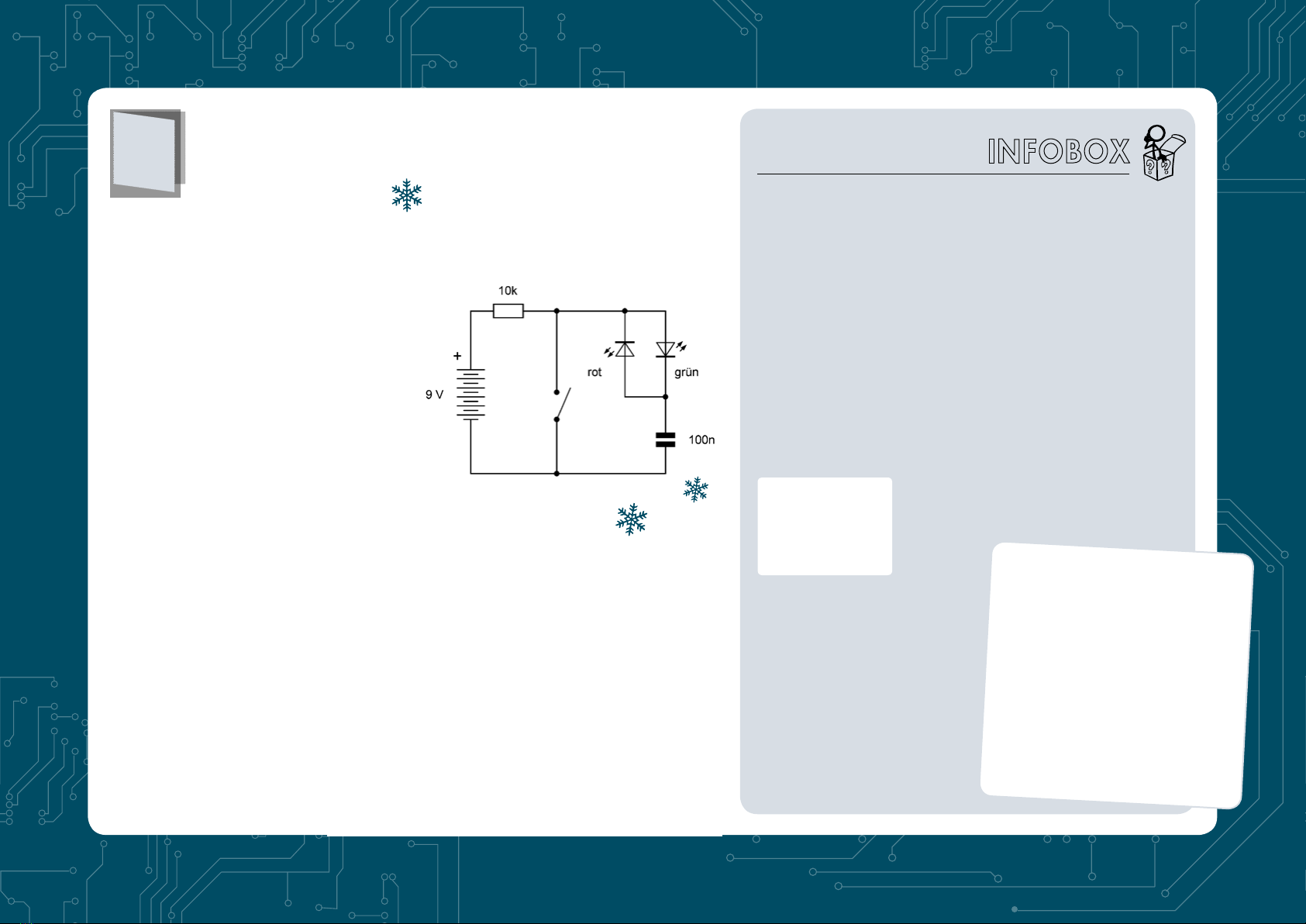
A capacitor consists of two metal surfaces
with an insulating layer between them.
Therefore, it is shown in the circuit diagram
with two unconnected lines. The component
also has an outer protective layer and can
look rather different depending on the make.
In the assembly pictures, a blue, square
capacitor is depicted, yours is round and
light brown. The inscription indicates the
capacity of this capacitor. This is a measure
of how much energy the capacitor contains at
a given voltage. The unit of capacity is called
Farad (after the famous researcher Michael
Faraday). The smaller units are microfarad
(µF), nano-farad (nF) and picofarad (pF).
The label 104 stands for 1, 0, 0000, i.e.
100,000 Picofarad, 100,000 pF = 100 nF.
On the sixth day on your calendar, you will
find new component behind the door: a
capacitor. It is a small, light brown disc with
two wires. On it you will find the inscription
104, which stands for 100 nF (100 Nano-
farad). A capacitor can be charged and
discharged. If you set the main switch 1 to
ON, it is charged. You can then turn it off
again, wait a little and press the button. This
creates a small LED flash that discharges
the capacitor. You can think of it as a kind
of battery that can be recharged over and
over again. However, your charged capacitor
contains very little energy.
6
Coloured flashes of light
Behind the seventh door you’ll find another
cable. Now build your circuit and insert
the red LED. Pay attention to the direction
of installation! The red LED appears to
be installed the wrong way around, i.e.
with the cathode towards the positive
pole of the battery. Using the button, you
can alternately charge (contact open) or
discharge (contact closed). When charging,
a green flash of light is generated, when
discharging, a red light appears. You
can repeat the alternating charging and
discharging as often as you like. Each time
you press the button, a red flash will appear;
once you release it, a green flash will appear.
Your battery delivers direct
current. This means that
the current always flows
in the same direction. In
your circuit, however, an
alternating current is created
when activating your push
button. In one direction
the green LED shines, in
the other direction the red
one will shine. Therefore, both LEDs in this
circuit had to be installed with different
directions.
7
The PTC fuse
All your experiments are
secured by a fuse to help
if a mistake occurs. If you
accidentally short-circuit a
cable, it could become glowing
hot, or the battery could heat
up, break, or even explode. But
the fuse will prevent that from
happening.
Many fuses just blow when you
cause a short circuit. You will
then need a new fuse. But your
special fuse is different. This is
a self-resetting fuse, also known
as a PTC fuse. If too much
current flows during a short-
circuit, the PTC fuse becomes
hot and lets only a little current
through because its resistance
rises sharply. That’s where
the name comes from. PTC
stands for “Positive Temperature
Coefficient” and means that
the resistance increases as
the temperature rises. If you
then switch off the power and
eliminate the fault, it cools down
and is as good as new again.
Please do not try it out, as the battery
will quickly become unusable in the
event of a short circuit. Also, the PTC
fuse can reach about 60 degrees
and can easily burn your fingers. But
that would still be better than glowing
wires and exploding batteries. So
always remember: The safety device
is only there for emergencies, similar
to the emergency brake on a train.
Attention!
also be clearly seen. One metal plate is a
thin sheet. This then follows the insulating
layer of a thin, grey disc. The second metal
plate is a silver-plated surface. There is an
electrical attraction between the two metal
surfaces which change when the capacitor is
charged or discharged. This creates a small
movement that generates the noise.
Electrical noises
Piezoelectricity
The Greek word piezo means
pressure, and some materials
such as quartz have a
piezoelectric effect. If you press
on it, an electrical charge is
generated. Conversely, when
an electrical charge is applied,
a deformation occurs as if one
were pressing on the material.
The insulation in your piezo
speaker is ceramic, similar to
porcelain. Once an electrical
voltage is connected, the disc
bends slightly. This creates a
noise.
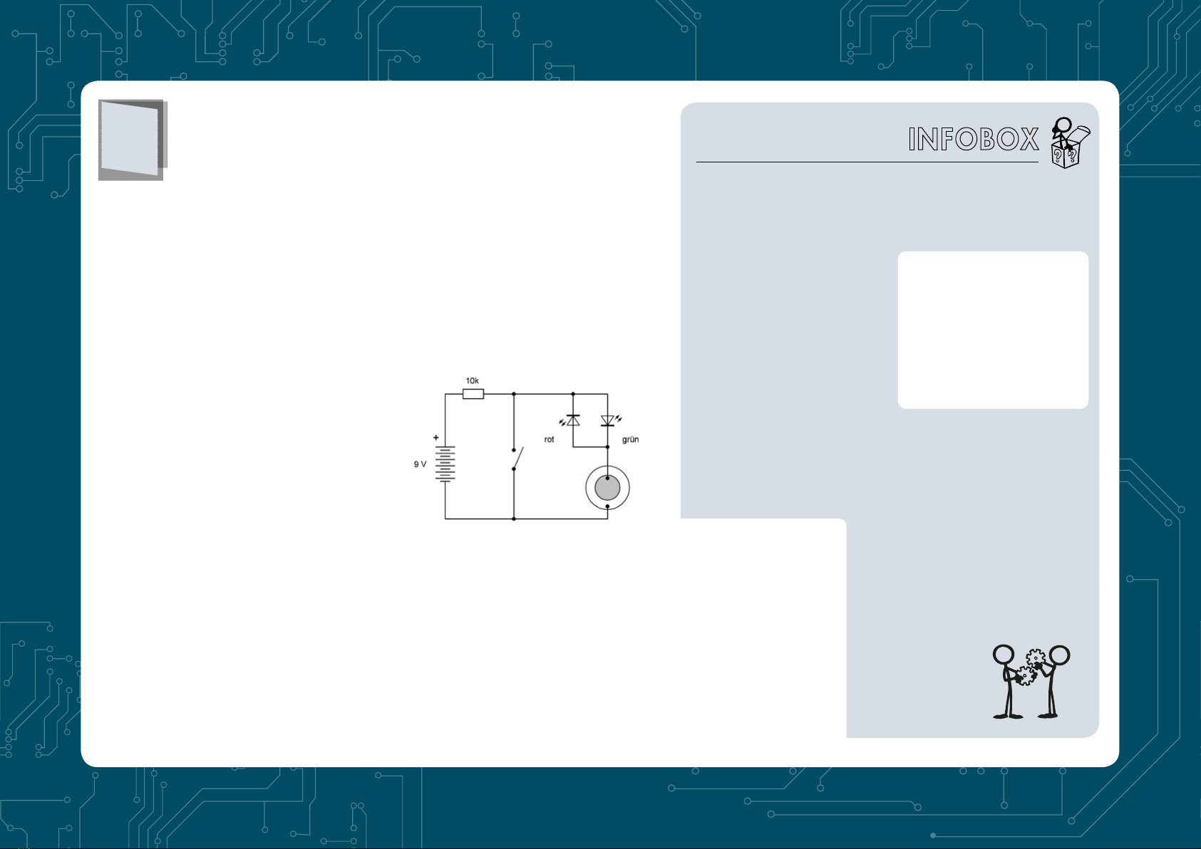
Open the 8th door and discover a small
piezo speaker with two wires. The
connecting wires are very thin and soft
and must therefore be protected just like
the battery cables. Make two more holes
in the protective foil of the adapter board
and guide the wires through from below.
Then feed them through the holes provided,
where they should stay until the last
experiment.
In this circuit, there is also a push switch,
and once again a small red and green light
will flash each time the switch is activated.
You will also now hear a soft but clear click
from the speaker each time. However, the
click of the snap-in switch may drown out
the speaker. Use a metal wire or object to
connect the two terminals of the button to
make the click quieter.
The comparison with the previous
experiment has already proven that the
piezo speaker functions like a capacitor.
And indeed, the structure of a capacitor can
8

charging current will flow, slowly charging
the piezo converter. The result is only a
slow, silent deformation. Once the contact
is closed, on the other hand, a sudden
discharge with rapid deformation and a
distinct cracking will occur.
Behind the 9th door you will find a new
resistor with the colours brown, black and
green. It has 1,000 kΩ(Kiloohm), so a 1 MΩ
(Megaohm). This very large resistor provides
a very small current that only slowly charges
the piezo transducer. Open and close the
contact several times. Both LEDs will clearly
flash. But the piezo speaker only produces a
crack when the contact is closed.
Braked current
9
Once again you can also use a wire or other
metal object if the button is too loud. Once
the contact is opened, however, no audible
noise is generated. The reason for this is the
large resistance in the circuit. Only a small
Open the 10th door and remove
another resistor. It is 2.2 kΩand has
three red coloured rings. Now build
a circuit with the piezo speaker, the
resistor and two LEDs. The battery is
not connected and may be removed
from the battery clip. The push
button should be pressed for the first
experiment. Now lightly tap the piezo
disc. This will again result in weak red
and green flashes of light. Attention!
You must not use too much force,
otherwise the ceramic disc could
break.
The experiment has shown that the
piezo speaker can not only convert
electrical energy into sound, but
also vibrations into electrical energy.
The same component functions as a
speaker, microphone and electrical
generator. Therefore, it is also called a
“piezoelectric sound transducer”.
Deformation owing to pressure on
the membrane causes charging and
thus generates electrical energy. But
the same also achieves a change in
temperature. It’s easy to try. Open the
switch and hold your warm finger
against the membrane for a few
seconds. Then close the contact. It will
cause a crackling sound and a flash of
light. Then open the contact and wait
a little longer until the pane has cooled
down again. Closing the contact again
generates another crackling sound
and a second flash of the other colour.
Use a cable instead of the push button
to hear soft sounds from the piezo
transducer.
Light flashes without battery
10

Amplified current
11
On the eleventh day you will receive an
important component of your calendar:
the transistor. The transistor has three
connections which should not be confused
with each other. They are called emitter
(E), base (B) and collector (C). By the way,
the abbreviation C comes from the English
spelling (collector). The emitter should
be connected to the negative terminal of
the battery. The flat, labelled side of the
transistor must point to the left.
The experiment shows the typical behaviour
of a transistor. If the pushbutton switch is
still open, the green LED shines dim, but
the red LED is very bright. If you press the
button, the red LED goes out. The transistor
Transistors
The transistor in your experiment
contains a silicon crystal. Silicon
(Si) is contained in large quantities
in normal quartz sand (quartz =
silicon oxide). It belongs to the
group of semiconductors, i.e.
substances that neither conduct
electricity well, such as metals, nor
insulate it well, such as glass or
rubber. In order to achieve a very
specific conductivity, tiny traces
of other substances are added to
the pure silicon. Depending on the
type of these substances, N-silicon
or P-silicon is obtained. There
are three layers in your transistor:
NPN. Other types have a different
layer sequence, namely PNP.
They function similarly, but with a
different current direction.
Transistors are important
components in all areas of
electronics, in radios and
televisions as well as in
smartphones and computers.
Transistors are installed
everywhere. It is therefore
worthwhile to understand exactly
how a transistor works.
Take a good look
at your transistor.
There’s a label:
BC547B. With
this description
you can order exactly the right
transistor, which is manufactured
by several companies by the way.
Or you can search the Internet
for the data sheet of this type. It
contains many properties and
measured values, some of which
are only clearly understood by
experts. In a nutshell: This NPN
transistor can withstand a voltage
of 50 V and a current of 100 mA.
And it can amplify the current at
least 200 times.
behaves like a switch. A small current
through the basic connection causes a
large current to be switched on through
the collector connection. However, if
you connect the base and emitter via the
button or pull out the green LED, the
red LED will also turn off.

Amplified light flashes
Because the transistor conducts current in
only one direction, the green LED must
ensure that current can also flow in the
opposite direction. As previous experiments
have shown, the piezo converter supplies an
alternating current. In this case, the green
LED shows the directly generated current,
while the red LED shows the current
amplified by the transistor.
Behind the 12th door you will find a resistor
marked 330 kΩ(Orange, Orange, Yellow).
Integrate it into this amplifier circuit using a
transistor. If you now tap softly on the piezo
disc, the red LED will emit a strong flash.
But weak flashes of light also come from the
green LED. Please note that the green LED
is installed in a different way than normal,
namely with the anode (long wire) at the
minus pole of the battery.
12
Touch switch
The Darlington Circuit
The connection of two transistors as shown in the circuit diagram is
called a Darlington circuit. Two transistors amplify more than one.
This is especially true for this circuit, where the already amplified
current is amplified again by a second transistor. The name comes
from its inventor, Sidney Darlington, who came up with the idea
in 1952. Both collectors are connected, and the emitter of the first
transistor flows to the base of the second transistor. The Darlington
circuit behaves like a single transistor with huge gain.
Behind door number 13, you will find a
second transistor of type BC547. Along with
the first transistor, it should now provide
even more amplification. Both collector
terminals are directly connected, and the
emitter of the first transistor leads to the base
of the second transistor. This circuit is called
a Darlington circuit. With this a touch switch
will be built here. If you touch the cable and
the resistor with your finger at the same time,
a very small, harmless and imperceptible
current flows through your finger, which is
amplified to such an extent that both LEDs
are switched on.
13
The speaker is again connected to the
collector of the transistors. And sometimes
you will hear strange sounds. Just touch
the base cable. Depending on where you
are, you may hear a crackling, humming or
buzzing sound from the speaker. The noise
can become even stronger if two people
touch both wires. It comes from the electrical
wiring in the room. If you also move your
feet on the floor, you can sometimes see the
LEDs flashing or flickering. It indicates the
electric charge of your body through friction
on the shoes.
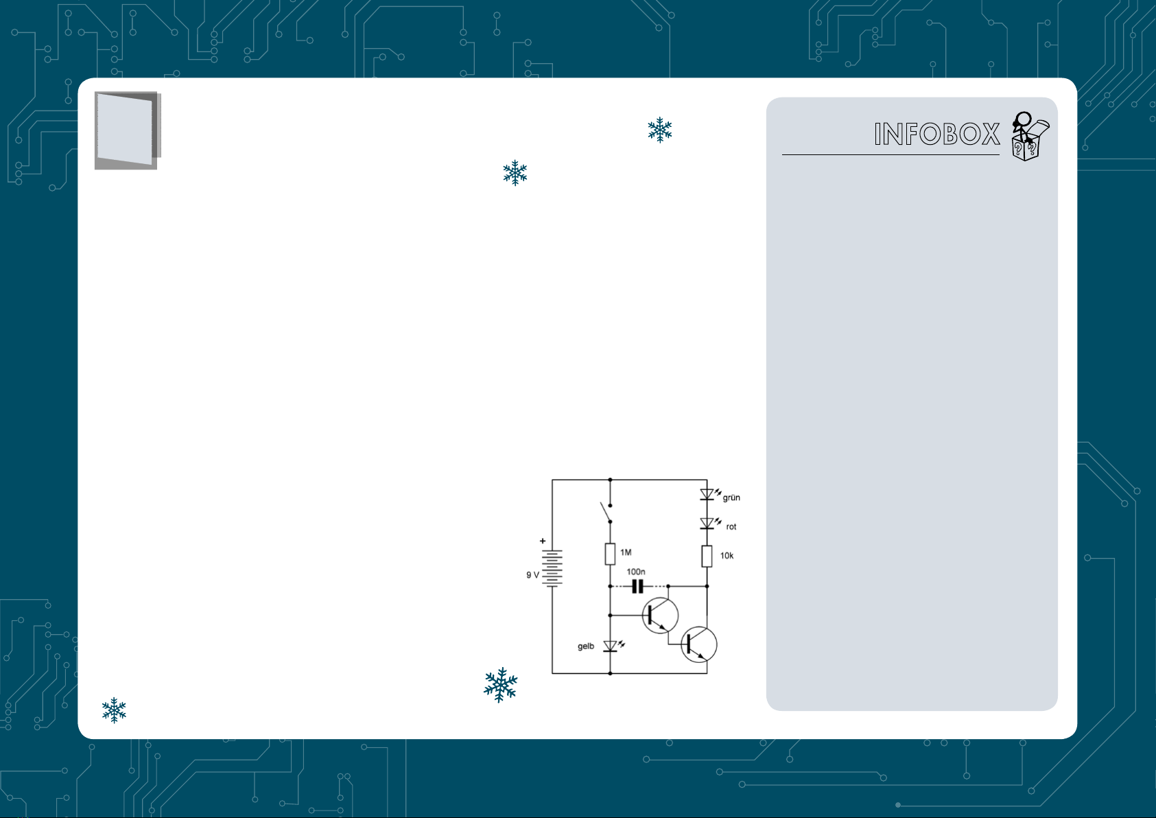
The light sensor
There is a yellow LED behind
door number 14. You could
install it in your circuit instead
of the red or green LED and
try out another colour. But it
can also perform a completely
different task. In this experiment,
the yellow LED is used as a light
sensor. When illuminated, it
delivers a very small current,
similar to a solar cell. This is then
amplified by two transistors and
causes the other two LEDs to
shine. Do not install the capacitor
first. Test the experiment using
a flashlight. The stronger you
illuminate the yellow LED, the
brighter the other two LEDs will
shine.
In addition, a capacitor is then
inserted into this circuit, which
serves to greatly slow down the
switching on and off. Only when
you have illuminated your photo
diode long enough, the red and
green LEDs will light up. After
switching off, they then continue
to glow for a long time and
only go out slowly. In addition,
the push button switch is also
installed. You can turn on the
light quickly and let it go out
slowly over half an hour.
14
Photodiode
Each diode consists of a semiconductor with
a PN barrier layer, which conducts the current
in one direction and does not let any current
through in the other, i.e. blocks the current.
In addition to light emitting diodes, there are
also rectifier diodes and photodiodes made
of silicon - the same material your transistors
are made of. A photodiode uses a particularly
large area so that a lot of light from outside
can penetrate into the barrier layer. There,
the light ensures that an electrical voltage is
generated and that the current can flow. An
LED has a similar structure, but only a very
small area. Therefore, the light-dependent
current is rather weak. However, after a large
amplification by the two transistors, it will be
sufficient for this experiment.
The red or green LED can also work as a
photodiode. Replace the LED in your circuit
and make sure you insert it in the right
direction. This way, you can explore which
LED is the best photo diode.
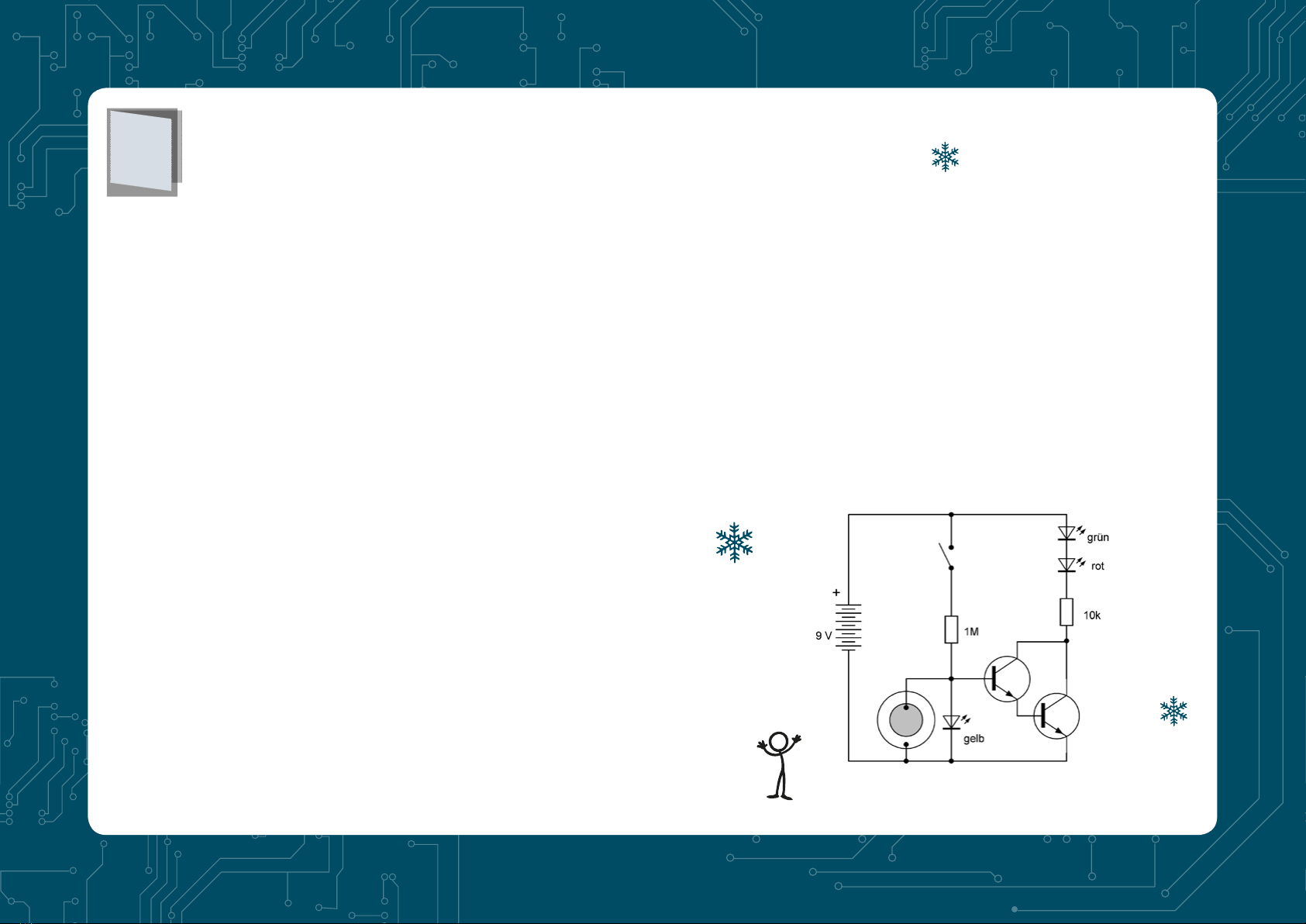
The motion detector
Behind the 15th door you’ll find
another cable. You will be building
using an infrared motion detector.
The actual sensor is the piezo disc.
You already know that when the
temperature changes, it generates
an electrical voltage. And this also
works without direct contact if you
get close. It is even better if you
darken the silver layer of the disc
with a soft pencil. Your warm hand
radiates infrared heat. When it hits
the blackened sensor, it heats up a
little. This produces only a very small
electrical current. That’s why you
need a good amplifier, which here
consists of a Darlington circuit. In
addition, a very small base current
is needed, which the is supplied by
the yellow LED depending on the
lighting. In addition, there are buttons
for continuous light.
Wait a while until the red and green
LEDs shine evenly and dimly. With
a short push of the button you can
shorten the waiting time. Then hold
your hand about 5 cm away from the
piezo disc. After a few seconds, the
brightness of the LEDs will change.
Remove the hand and observe the
opposite change in brightness. The
two LEDs can therefore indicate the
approach of the hand. However, the
direction of the change cannot be
predicted. You can change them by
swapping both cables of the piezo
speaker. The LEDs should shine
brighter if you hold your hand closer
to the piezo disc. With this you have
built night light with a proximity
sensor.
15

One light amplifier
16
Open door number 16 and take out a
new component. At first glance, it looks
like an LED in a clear housing, but in
fact it is a light sensor; more precisely,
a photo transistor. Install it along with
a resistor and an LED. Make sure you
install it the right way around. Unlike
what you know about an LED, the long
wire has to be connected to the negative
terminal, because that is the emitter. The
red LED lights up brighter when more
light falls on the photo transistor. The
red LED goes out in complete darkness.
Like a normal transistor, the
phototransistor has an emitter (long
wire) and a collector (short wire). There
is also a base, but it has no connection.
The base current is supplied by a
built-in photodiode. If you look at the
transparent case from the front, you
will see a relatively large black area.
That’s the light-sensitive photodiode.
It is significantly larger than the area
of an LED crystal. Therefore, the
phototransistor is much more sensitive
than the LED in your light sensor from
experiment 14.
This manual suits for next models
1
Table of contents
Popular Toy manuals by other brands


Eduard
Eduard J2M3 Raiden exterior quick start guide

Mega Bloks
Mega Bloks CHARLIE CNC84 Service manual

Mega Bloks
Mega Bloks Collector Series instructions

Monogram
Monogram KIT 5089 Assembly manual

Eduard
Eduard ZOOM F/A-18F seatbelts STEEL quick start guide

E-BLOX
E-BLOX CIRCUIT BUILDER 115 instruction manual


