Makita EBH252U Manual

March 2016
TECHNICAL INFORMATION
OFFICIAL USE
for ASC & Sales Shop
CONCEPT AND MAIN APPLICATIONS
Straight gasoline (lead-free gasoline for automobiles)
Nylon cutting head
0.5
24.5
Fuel tank capacity: L
Standard cutting tool
Engine Displacement: mL
Fuel
4-stroke
Specification EBH252L
Model
Type
Starting system Recoil starter, with mechanical decompression
Loop handleHandle style
Engine oil
Carburetor
SAE10W-30 oil
in the Class SF or higher of API Classification
Diaphragm
Net weight*2: kg (lbs) 5.2 (11.5)
*1 No load speed of the engine when installed on the brushcutter
*2 Dry weight, without universal guard, cutting tool and shoulder harness
Rapid start
Nylon cutting head
EBH253L
EBH253U
Loop handle
5.3 (11.7)
No
230mm (9") diameter
4-tooth star blade
EBH252U
Bike handle
5.7 (12.6)
No
No
230mm (9") diameter
4-tooth star blade
9,000No load speed*1: min-ı= rpm 9,00010,000 10,000
Bike handle
5.9 (13.0)
Yes
YesWaist cushion
620 (24-3/8) 330 (13)
L
W
H
Dimensions: mm (")
Width (W)
Height (H)
Length (L) 1,770 (69-3/4)
490 (19-1/4) 265 (10-3/8)
EBH252U
EBH253U
EBH252L
EBH253L
EBH252U
EBH253U
EBH252L
EBH253L
L
W
H
EBH252U, EBH252L
EBH253U, EBH253L
Petrol Brushcutter
These four models are 4-stroke petrol brushcutters developed
in compliance with EU Stage 2 exhaust emission regulations.
Their main features are:
• 4-stroke engine for low noise and clean exhaust emission
• Ergonomic handle for higher maneuverability
See “Specification” below for the specification differences
between the four models.
Note: These four products are not in compliance with
the regulations of San Dimas.
1 / 40
Model No.
Description
Specification
Standard equipment
Blades, Nylon cutting head
Optional accessories
Note: The standard equipment for the tool shown above may vary by country.
4-tooth star blade 230mm (9") (for EBH252U, EBH253U)
Nylon cutting head (for EBH252L, EBH253L)
Universal guard (=Protector)
Shoulder harness with double shoulder straps (for EBH252U, EBH253U)
Shoulder harness with single shoulder strap (for EBH252L, EBH253L)
Socket wrench
Hex wrench (for M5)
Hex wrench (for M6)
Wire clamp (for tying cables) (for EBH252U)
Oil bottle

1INDEX
1INDEX .......................................................................................................................................................................................... 2
2CAUTION..................................................................................................................................................................................... 3
3HANDLING OF GASKET........................................................................................................................................................... 3
4NECESSARY REPAIRING TOOLS............................................................................................................................................ 4
5LUBRICANT AND ADHESIVE APPLICATION....................................................................................................................... 4
5-1 Recoil starter, Gear case assembly, Shaft ............................................................................................................................. 4
5-2 Cylinder block section.......................................................................................................................................................... 5
5-3 Cylinder block assembly...................................................................................................................................................... 6
5-4 M5x40 Hex socket head bolts for securing Muffler............................................................................................................. 6
6REPAIR ......................................................................................................................................................................................... 7
6-1 Engine and Shaft .................................................................................................................................................................. 7
6-1-1 Disassembling ............................................................................................................................................................. 7
6-1-2 Assembling.................................................................................................................................................................. 8
6-2 Shaft pipe complete.............................................................................................................................................................. 9
6-2-1 Disassembling ............................................................................................................................................................. 9
6-2-2 Assembling.................................................................................................................................................................. 9
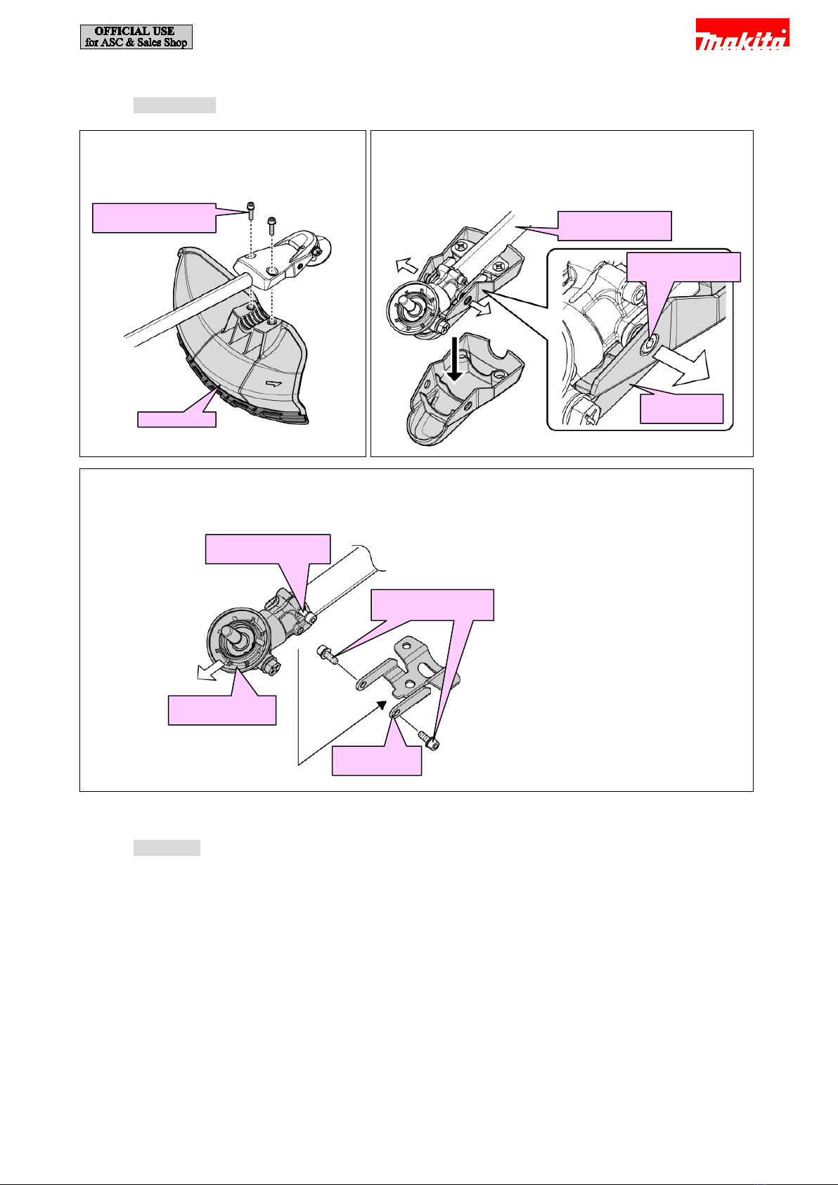
6-3 Gear case assembly ............................................................................................................................................................ 10
6-3-1 Disassembling ........................................................................................................................................................... 10
6-3-2 Assembling................................................................................................................................................................ 11
6-4 Control lever assembly....................................................................................................................................................... 11
6-4-1 For EBH252U and EBH253U................................................................................................................................... 11
6-4-2 For EBH252L and EBH253L.................................................................................................................................... 13
6-5 Clutch................................................................................................................................................................................. 16
6-5-1 Disassembling ........................................................................................................................................................... 16
6-5-2 Assembling................................................................................................................................................................ 17
6-6 Flywheel............................................................................................................................................................................. 18
6-6-1 Disassembling ........................................................................................................................................................... 18
6-6-2 Assembling................................................................................................................................................................ 18
6-7 Clutch case ......................................................................................................................................................................... 19
6-7-1 Disassembling ........................................................................................................................................................... 19
6-7-2 Assembling................................................................................................................................................................ 20
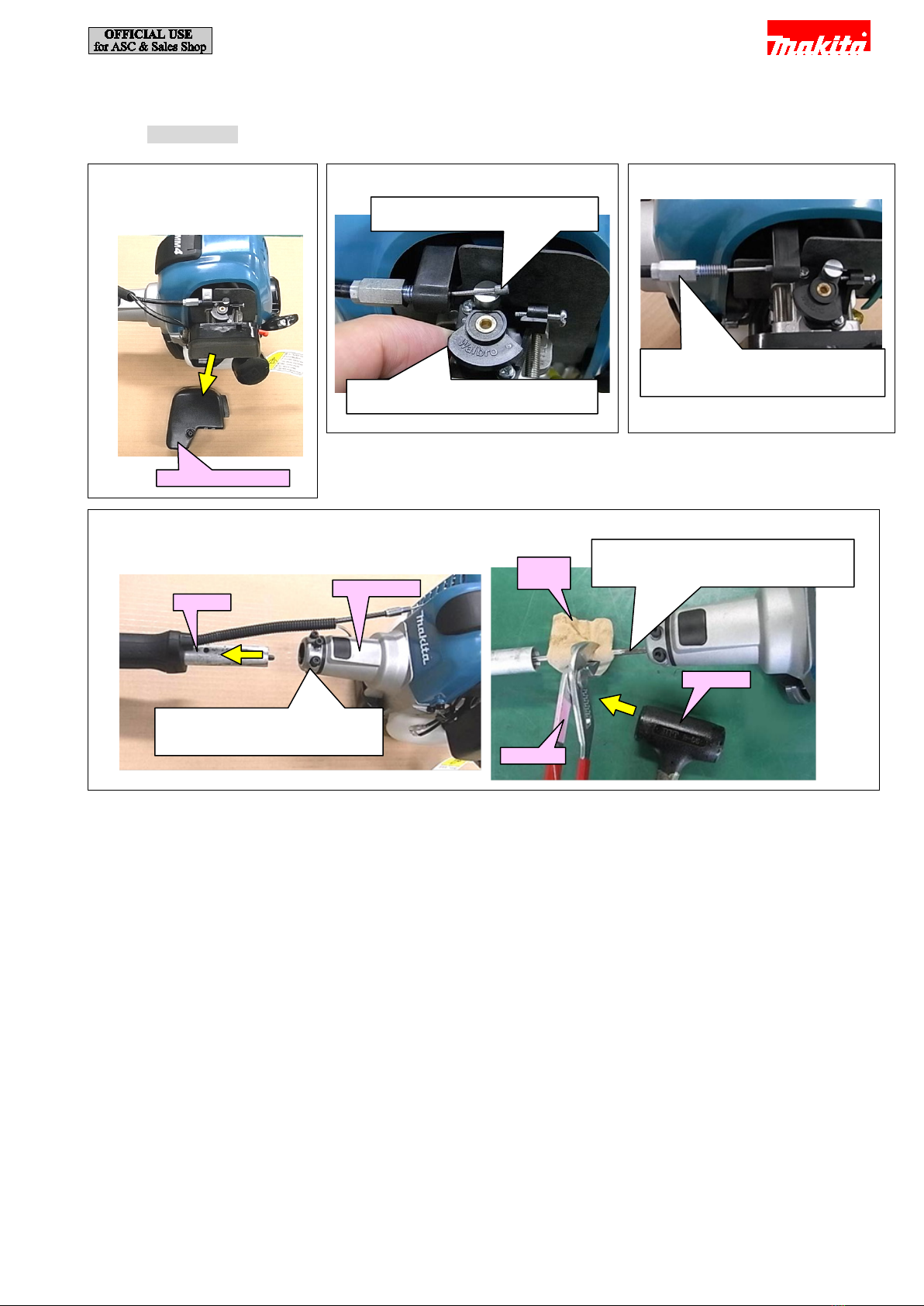
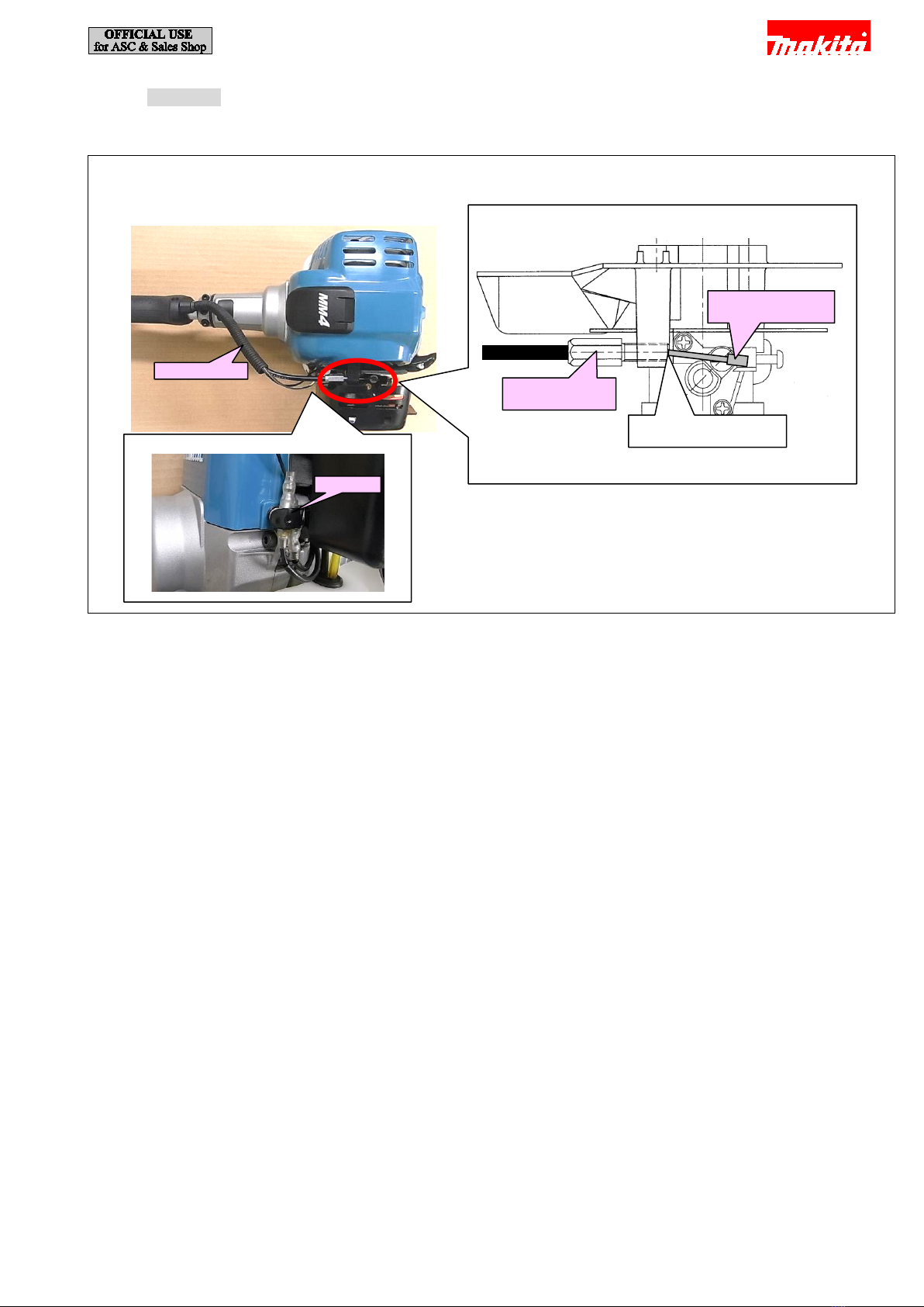
6-8 Carburetor .......................................................................................................................................................................... 21
6-8-1 Disassembling ........................................................................................................................................................... 21
6-8-2 Assembling................................................................................................................................................................ 22
6-9 Check of Spark plug........................................................................................................................................................... 22
6-10 Ignition coil ........................................................................................................................................................................ 22
6-10-1 Disassembling ........................................................................................................................................................... 22
6-10-2 Assembling................................................................................................................................................................ 23
6-11 Plug cap.............................................................................................................................................................................. 23
6-11-1 Disassembling ........................................................................................................................................................... 23
6-11-2 Assembling................................................................................................................................................................ 23
6-12 Checking of Ignition coil.................................................................................................................................................... 24
6-13 Checking of Ignition coil (cont.) ........................................................................................................................................ 25
6-14 Recoil starter Assembly...................................................................................................................................................... 26
6-14-1 Disassembling ........................................................................................................................................................... 26
6-14-2 Assembling................................................................................................................................................................ 28
6-14-3 Assembling................................................................................................................................................................ 29
6-15 Pulley (plate) (EBH252 series) .......................................................................................................................................... 30
6-15-1 Disassembling ........................................................................................................................................................... 30
6-15-2 Assembling................................................................................................................................................................ 30
6-16 Pulley (aluminum diecast) (EBH253 series) ...................................................................................................................... 31
6-16-1 Disassembling ........................................................................................................................................................... 31
6-16-2 Assembling................................................................................................................................................................ 31
6-17 Engine block ...................................................................................................................................................................... 32
6-17-1 Disassembling ........................................................................................................................................................... 32
6-18 Engine block (cont. - Piston section).................................................................................................................................. 36
6-18-1 Replacing................................................................................................................................................................... 36
6-19 Engine block (cont. ) .......................................................................................................................................................... 37
6-19-1 Assembling................................................................................................................................................................ 37
6-20 Final check......................................................................................................................................................................... 39
7TIGHTENING TORQUE SPECIFICATIONS........................................................................................................................... 40
2 / 40

2CAUTION
Repair the machine in accordance with “Instruction manual” or “Safety instructions.
Follow the instructions described below in advance before repairing:
· Wear gloves.
· Remove the cutting tool from the unit, and if it is a saw blade, attach the blade cover to the blade.
· When the engine is hot from use, cool down the engine enough or you can get burned.
· Remove remaining fuel from Fuel tank and Carburetor completely. [FLAMMABLE MATERIAL KEEP FIRE AWAY]
· Remove Spark plug cap from Spark plug.
· Repair the engine on a stable workbench and in a clean workplace kept as free of dust and debris as possible.
· In order to avoid wrong reassembly, draw or write down where and how the parts are assembled, and what are the parts.
· It is also recommended to have boxes ready to keep disassembled parts by group.
· Handle the disassembled parts carefully. Clean and wash them properly.
· If some bolts and screws are too tight, use an impact driver.
· Tighten the bolts and the screws to the specified torque as shown in "7 TIGHTENING TORQUE SPECIFICATIONS".
· Each time after you mounted a main part of the engine such as the piston, check if it moves smoothly without abnormal noise by
manually turning the crankshaft.
· After completion of reassembly, check for loose parts or abnormal noise and vibration by manually turning the crankshaft.
3HANDLING OF GASKET
Once Gasket is removed:
[1] Clean up the mating surfaces where the gasket was installed to maintain its sealing performance.
[2] Replace the removed Gaskets with new ones. Do not reuse them.
3 / 40

4NECESSARY REPAIRING TOOLS
Code No.
Description
Use for
1R005
Retaining ring pliers RT-2N
removing Retaining ring R-32
1R070
Tachometer
measuring engine rpm
1R181
Ignition checker
diagnosing Ignition coil
1R183
Clutch extractor
removing Pulley
1R219
Torque wrench shaft 7-23N·m
tightening bolt, nut, screw to the specific torque
1R220
Ratchet head 9.5
1R238
Round bar for Arbor 9-100
removing Clutch drum
1R258
V Block
1R269
Bearing extractor (small)
removing Ball bearings
1R291
Retaining ring S and R pliers
removing Retaining ring S-12
1R311
Retaining ring pliers with Long bent nails
removing Retaining ring
1R316
Wrench for bearing retainer
disassembling Pulley (For EBH253L and EBH253U only)
1R364
Flywheel puller
removing Flywheel
1R366
Feeler gauge set
adjusting Ignition coil, Spark plug, Rocker arm
1R372
Crankshaft lock bolt M10
locking Piston
5LUBRICANT AND ADHESIVE APPLICATION
Apply the following lubricants and adhesives.
5-1 Recoil starter, Gear case assembly, Shaft
Spiral spring
Gear case
assembly
8g
Starter case
Shaft pipe
Shaft
4g
Reel
Lubricant
Amount
Makita grease FA No.2
a little
Fig. 5-1-1
4 / 40

5-2 Cylinder block section
Needle bearing
Oil seal 12
Oil seal 10
Outer
circumference of
Piston ring set
Crankshaft
assembly
Sealing lips of
Oil seals
Rod portions of Intake valve,
Exhaust valve in Cylinder
Lubricant
Amount
Makita grease FA No.2
a little
4-stroke engine oil
a little
Fig. 5-2-1
Cam gear section
Marking on
Cam gear
Marking on
Crankcase
Pin 5
Cam lifter
Pin 4
Rod 2.5
5 / 40

5-3 Cylinder block assembly
Use parts cleaner or the like to remove grease from the mating surface of Crankcase to Cylinder block, and then apply ThreeBond
1215 or 1216 as shown below.
5-4 M5x40 Hex socket head bolts for securing Muffler
Once M5x40 Hex socket head bolts are removed or loosened, apply Loctite 271 or 272 on them.
Fig. 5-3-1
Oil route
Note:
Liquid gasket should
not be come into here.
Surface where
ThreeBond 1215 or
1216 should be applied
Crankcase
6 / 40

6REPAIR
6-1 Engine and Shaft
6-1-1 Disassembling
Fig. 6-1-1-1
[1] Remove Air cleaner cover.
Air cleaner cover
Fig. 6-1-1-2
Fig. 6-1-1-3
[4] Loosen Adjust screw* and then
remove Control cable.
*the component of Control cable
[3] Remove the cylindrical end
of Control cable.
[2] Push to open the throttle portion
of arburetor by a finger.
Fig. 6-1-1-4
Clutch case
[5] Loosen three Hex socket head
bolts, then separate Shaft from
Clutch case.
Shaft
Waste
cloth
Pliers
[6] If the end of Shaft is stuck at the
spline engagement, use a waste cloth
and water pump pliers to pull it out.
Hammer
7 / 40

6-1-2 Assembling
[1] Assemble by reversing the disassembling procedure.
Fig. 6-1-2-1
[2] Route Control cable over the shaft as shown below.
Adjust screw of
Control cable
Cylindrical end of
Control cable
[4] Insert Adjust screw
all the way.
[3] Bundle Lead units with Clamp.
Clamp
Control cable
8 / 40

6-2 Shaft pipe complete
6-2-1 Disassembling
6-2-2 Assembling
Assemble by reversing the disassembling procedure.
Fig. 6-2-1-1
[1] Loosen two M6x30 Hex socket head bolts,
then remove Protector.
Fig. 6-2-1-2
[2] Expand the space between the side wall of Protector cover and
M5x14 Hex socket head bolt, then remove Protector cover
from Shaft pipe complete.
Protector
cover
Shaft pipe
complete
Protector
M6x30 Hex socket
head bolt (2 pcs.)
M5x14 Hex socket
head bolt
Fig. 6-2-1-3
[3] Remove two M5x14 Hex socket head bolts, then remove Protector clamp.
[4] Loosen M5x25 Hex socket head bolt, then remove Gear case assembly.
M5x25 Hex socket
head bolt
M5x14 Hex socket
head bolt
Protector
clamp
Gear case
assembly
9 / 40

6-3 Gear case assembly
6-3-1 Disassembling
[1] Remove Gear case assembly. (See 6-2-1 Disassembling.)
Fig. 6-3-1-1
Fig. 6-3-1-2
Gear case
assembly
[4] Remove Spiral bevel
gear 14 section by
tapping Gear case
assembly with a plastic
hammer.
Note: It must be removed
first to remove Cutter
shaft.
Spiral bevel
gear 14 section
Fig. 6-3-1-3
[5] Remove Retaining
ring R-28 with
1R311.
Ball bearing
6001LLU
Cutter shaft
set
[6] Remove Cutter shaft section by
tapping Gear case assembly.
Note:If Cutter shaft section is hard to be removed,
warm the rear side with a drier.
Fig. 6-3-1-4
[7] Disassemble Cutter shaft section with 1R269 or Arbor press, etc.
Note: Replace Spiral bevel gear 14 and Cutter shaft at the same time as Cutter shaft set.
Ball bearing
6001LLU
Retaining
ring S-9
Ball bearing
609ZZ
Cutter shaft
set
Spiral bevel
gear 14
Cutter shaft
[3] Remove Retaining ring
R-24 with 1R311.
[2] Remove M8x10
+Hex bolt with R.
10 / 40

6-3-2 Assembling
[1] Assemble by reversing the disassembling procedure.
Note: First assemble Cutter shaft, then assemble Spiral bevel gear 14.
6-4 Control lever assembly
6-4-1 For EBH252U and EBH253U
6-4-1-1 Disassembling
Fig. 6-4-1-1-1
Remove two M6x25 Hex socket head bolts, then remove Pipe clamp from Pipe shaft.
Pipe shaft
Pipe clamp
M6x25 Hex socket head bolt
(2 pcs.)
Fig. 6-3-2-1
[2] When the gear room is cleaned up, apply 8g of Makita grease FA No.2 in either of the following ways:
· during assembling: apply grease into Gear case assembly
· after assembling: apply grease from the threaded hole for M8x10 +Hex bolt with a grease gun
Gear case assembly
8g
11 / 40

6-4-1-2 Assembling
[1] Assemble by reversing the disassembling procedure.
Fig. 6-4-1-2-1
[2] Assemble
Lock-off lever
to Lever case L.
[7] Assemble Throttle
lever to Lever case
L.
[4] Set
Corrugate
tube in the
unit.
Route the lead wires
through the hole.
Set the lead wires
into each lead holder.
[5] Assemble
Control cable to
Throttle lever.
[8] Assemble Cable holder.
Cable holder
Corrugate
tube
Stop switch lead
wires must have a
margin of 25-30mm.
[3] Assemble Torsion spring 7 to
Lock off lever.
[9] Assemble Switch lever to
Switch cover.
Hang the spring on the rib.
[6] Assemble Torsion spring 11 to
Throttle lever.
Fig. 6-4-1-2-2
[10] To prevent Lever case R from contacting Leaf
spring, assemble Leaf spring to Switch lever in
parallel.
Fig. 6-4-1-2-3
[11] Set Leaf spring between the triangular rib and the
screw boss, then assemble Lever case R to Lever
case L as shown below.
Lever case R
Triangular
rib
Screw
boss
Lever case L
Leaf spring has
to be set in this
space.
Leaf spring
Switch lever
Push this section all the way.
Triangular
rib
Screw boss
12 / 40

6-4-2 For EBH252L and EBH253L
6-4-2-1 Disassembling
Fig. 6-4-2-1-1
Blade
side
Loop handle 24
Handle clamp 24
Shaft pipe complete
[1] Remove four M5x30 Pan
head screw, then
disassemble Loop handle.
Fig. 6-4-2-1-2
[2] Loosen four 4x18 Tapping screws, then remove Lever
case R.
Lever case R
Note: Do not loosen Hex
socket head bolts.
Fig. 6-4-2-1-3
[3] Remove Control lever assembly as shown below.
Control cable
Lock lever
Torsion spring 7
Torsion spring 11
Throttle
lever
Lever case L
[4] Remove the cable
nipple from Throttle
lever.
(1)
(2)
Fig. 6-4-2-1-4
Switch lever
Switch cover
Leaf spring
[5] Loosen PT3x16 Tapping screw,
then remove Switch cover.
Lever case L
13 / 40

6-4-2-2 Assembling
[1] Assemble by reversing the disassembling procedure.
Fig. 6-4-2-2-1
[2] Route the wire end of Lead unit
through the hole on Lever case L.
Fig. 6-4-2-2-2
[3] Fix the wire end of Lead unit as
shown below.
Fig. 6-4-2-2-3
[4] Fix Lead unit to each Lead wire
holder as shown above.
Fig. 6-4-2-2-4
[8] Fix Torsion
spring 11 to
Throttle lever.
[9] Put the cable nipple of
Control cable as shown
below.
[10] Hang the tail of
Torsion spring
11.
[5] Put the end of
Control cable as
shown below.
[6] Put Torsion spring 7 of Lock lever
section as shown below.
[7] Put Corrugate tube
while aligning its
shape with Lever
case L.
Fig. 6-4-2-2-5
[11] Expand outward Leaf spring a little,
then attach Switch lever.
The position where Leaf spring is set
Switch lever
Throttle
lever
Leaf spring
Switch
lever
Apply Makita
grease FA No.2.
Leaf
spring
14 / 40

Fig. 6-4-2-2-6
[12] Each part of Pipe shaft and the position where each label is attached are as follows:
10±2
10±2
10±2
10±2
10±2
10±2
640±5
435±5
235±5
85
640±5
435±5
235±5
170
320
640±5
230
EBH253U
EBH252U
EBH252L
EBH253L
100
Control lever
assembly
Note: The hole of Shaft pipe complete must
be faced to upward. (For all models)
Hanger
Cushion
Makita’s logo
label
Caution
label
Serial
number
label
Caution
label
Pipe holder
Fix Hanger next to
Control lever.
Pipe shaft
Wire clamp
15 / 40

6-5 Clutch
6-5-1 Disassembling
[1] Separate Shaft section from Engine section. (See 6-1 Engine and Shaft.)
Fig. 6-5-1-1-6
Fig. 6-5-1-1
[2] Remove two 5x12 Pan
head screws.
Fig. 6-5-1-1-2
M4x25 Pan head screw (2 pcs.)
[4] Remove Cylinder cover.
[3] Remove two M4x16
Pan head screws.
Fig. 6-5-1-1-4
Stand
[7] Remove two M5x14 Pan
head screws, then remove
Stand.
[6] Remove two M5x12 Pan
head screws, then remove
Tank guard.
Tank
guard
Fig. 6-5-1-1-5
[8] Remove Recoil starter.
Note: When you remove Clutch
section, be sure to remove
Recoil starter set to prevent it
from damage.
Recoil starter
[9] Loosen three M5x16 hex socket
head bolts, then remove Clutch case.
Clutch case
Fig. 6-5-1-1-7
[10] Remove M6x25 shoulder hex bolt by
turning it counterclockwise with an
impact driver and Socket bit 13.
Note: Do not remove Spark plug because
compressed air resistance in
Cylinder has to be used for the
disassembling.
Socket bit 13
Fig. 6-5-1-1-3
[5] Remove two M4x25 Pan head
screws.
Note: Tank guard, Starter and Spacer
are jointly fastened, and make
sure not to lose Spacer.
Spacer
Starter
Tank guard
M6x25 shoulder hex bolt
Impact driver
M5x16 hex socket head
bolt (3 pcs.)
16 / 40

6-5-2 Assembling
[1] Assemble by reversing the disassembling procedure.
Fig. 6-5-2-1
[2] Assemble two Washers 6, two Clutch shoes, Tension spring 7, two Washers 8 and two M6x25 Shoulder hex bolts to
Flywheel.
Washer 6 (2 pcs.)
Tension spring 7
Washer 8 (2 pcs.)
Note: Face each curve
toward Clutch
shoe.
[3] Screw 1R372 into the threaded hole for Spark
plug. Tighten two M6x25 Shoulder hex bolts to
7 to 10N·m with 1R219, 1R220 and Socket bit
13.
1R219
1R220
Fasten
1R372
Socket bit 13
Fig. 6-5-2-2
[4] Thrust Stand in the direction of the arrow and assemble it to Clutch case with two M5x14 Pan head screws
(The components of Stand set).
Clutch case
Stand
M5x12 Pan head screws (2 pcs.)
M5x14 Pan head screw (2 pcs. The component of Stand set)
Note: Do not mistake them for two M5x12 Pan head screws that fasten Tank
guard to Clutch case.
M6x25 Shoulder hex
bolt (2 pcs.)
marking of =>"
Clutch shoe (2 pcs.)
Note:
· Align the marking of "=>" and the rotational direction of the
engine.
·
Replace two Clutch shoes together.
17 / 40

6-6 Flywheel
6-6-1 Disassembling
[1] Remove Clutch. (See 6-5-1 Disassembling.)
6-6-2 Assembling
[1] Assemble by reversing the disassembling procedure.
Fig. 6-6-2-2
[3] Set 1R372 into the threaded hole for Spark plug.
Tighten M6x16 Hex head bolt to 9-11 N・m with
1R219, 1R220 and Hex socket 10.
[4] Set Clutch section in place. (See 3-4-5-2 Assembling.)
Fig. 6-6-1-2
1R364
[4] Remove Flywheel with
1R364.
Flywheel
[3] The center hole is
made by tightening
M6x16 Hex head
bolt.
Fig. 6-6-2-1
[2] Assemble Flywheel to Crankshaft assembly with
Woodruff key while aligning the keyslot to the keyway.
Flywheel
Note: Remove oil/grease
from their taper
por
tions with a spray
parts cleaner.
Set 1R372.
1R219
1R220
Remove Spark
plug.
Fig. 6-6-1-1
[2] Remove M6x16 Hex head
bolt (right hand thread) with
Socket bit 10.
Socket
bit 10
M6x16 Hex
head bolt
18 / 40

6-7 Clutch case
6-7-1 Disassembling
[1] Remove Clutch case. (See 6-5-1 Disassembling.)
Fig. 6-7-1-2
Fig. 6-7-1-1
Pipe bracket 2
Pipe damper 2
Clutch case
[2] Pull out Pipe bracket
2 together with Pipe
damper 2 and
separate each other.
[3] Push and pull out Pipe damper
1 together with Pipe bracket 1
and separate each other.
Pipe damper 1
Pipe bracket 1
[5] Set Clutch case on
two 1R258 and press
down Clutch drum
with an arbor press.
Note: Be careful not to
put the projection
of Clutch case on
1R258.
1R238
1R258
[4] Remove Retaining
ring R-32 with
1R005 through the
groove on Clutch
drum.
1R005
[6] Remove Retaining ring S-12
with 1R291.
1R291
Retaining ring S-12
Clutch drum
Projection of
Clutch case
19 / 40

6-7-2 Assembling
[1] Assemble by reversing the disassembling procedure.
Fig. 6-7-2-1
[2] Assemble Clutch drum.
[3] Be sure to fix retaining
ring R-32 between
Clutch drum and Ball
bearing 6001LLU.
Clutch case
Ball bearing
6001LLU
Clutch drum
[4] Spacer is
directional.
Fig. 6-7-2-2
Clutch case
Note: Pipe bracket should
be removed in
advance.
[5] Press-fit
Clutch drum.
Fig. 6-7-2-3
[6] Fix Retaining ring R-32 with 1R005 through the groove on
Clutch drum.
1R005
[7] Assemble Clutch case.
(See 6-5-2 Assembling.)
20 / 40
Other manuals for EBH252U
7
This manual suits for next models
3
Table of contents
Other Makita Brush Cutter manuals

Makita
Makita BCM2310 User manual

Makita
Makita EE2650H User guide

Makita
Makita EBH340U User manual

Makita
Makita DUX18 User manual

Makita
Makita RBC3100 User guide

Makita
Makita EM2650UH User manual

Makita
Makita EM3400U User manual

Makita
Makita EBH341L User guide

Makita
Makita EM2650UH User manual

Makita
Makita EM400MP User manual

Makita
Makita EBH252U User manual

Makita
Makita EM2500L User manual

Makita
Makita EM2550UH User manual

Makita
Makita EBH340U User manual

Makita
Makita RBC411U Manual

Makita
Makita RBC421L Operation instructions

Makita
Makita EM4350UH Manual

Makita
Makita RBC411 User manual

Makita
Makita EBH341U User guide

Makita
Makita BBC231U User manual