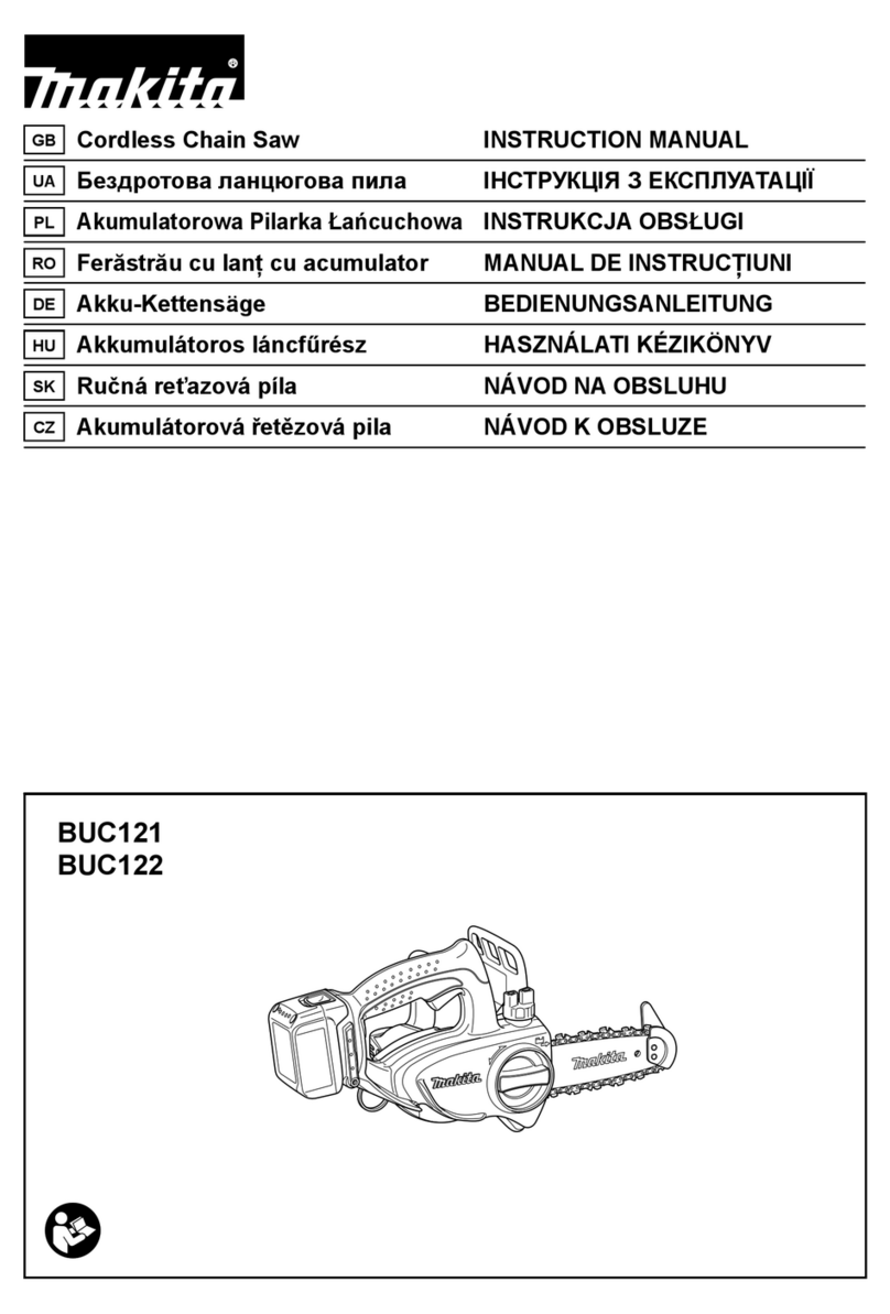
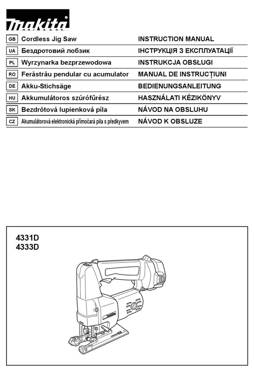
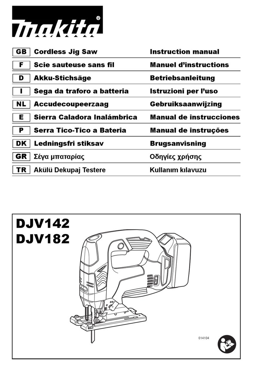
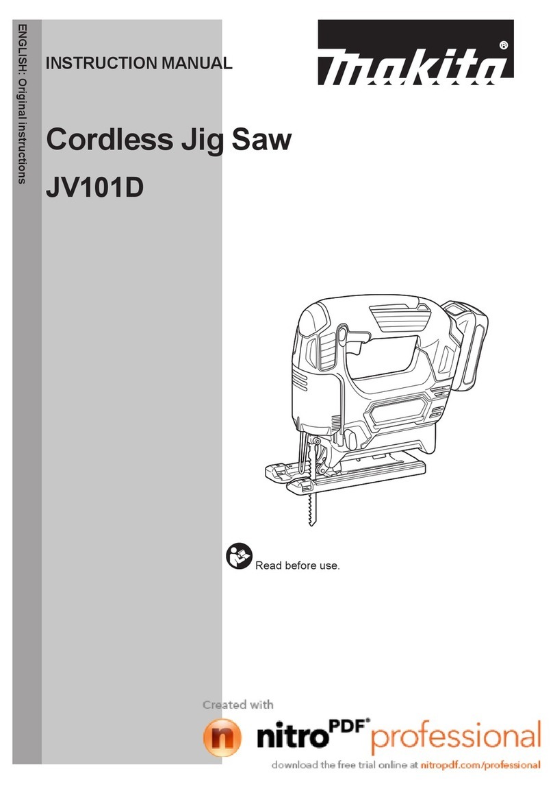
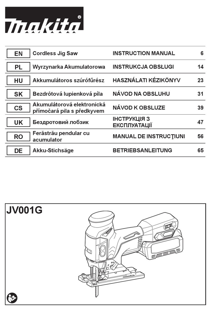
Makita JV103D User manual

JV103D
EN Cordless Jig Saw INSTRUCTION MANUAL 7
FR Scie sauteuse sans l MANUEL D’INSTRUCTIONS 13
DE Akku-Stichsäge BETRIEBSANLEITUNG 20
IT Seghetto alternativo a
batteria ISTRUZIONI PER L’USO 28
NL Accudecoupeerzaag GEBRUIKSAANWIJZING 35
ES Sierra Caladora Inalámbrica MANUAL DE
INSTRUCCIONES 43
PT Serra Tico-Tico a Bateria MANUAL DE INSTRUÇÕES 51
DA Akku stiksav BRUGSANVISNING 58
EL Φορητό παλινδρομικό πριόνι ΕΓΧΕΙΡΙΔΙΟ ΟΔΗΓΙΩΝ 65
TR Akülü Dekupaj Testere KULLANMA KILAVUZU 73

1
2
3
Fig.1
1
2
Fig.2
1
Fig.3
123
Fig.4
1
Fig.5
1
23
Fig.6
1
2
Fig.7
1
2
Fig.8
2

12
Fig.9
1
2
Fig.10
Fig.11
1
2
3
Fig.12
1
2
Fig.13
1
2
3
Fig.14
Fig.15
Fig.16
3

Fig.17
1
Fig.18
1
Fig.19
1
Fig.20
12
Fig.21
4

Fig.22
1
Fig.23
1
2
3
4
Fig.24
1
Fig.25
1
23
4
Fig.26
1
2
Fig.27
1
2
Fig.28
2
1
Fig.29
5

1
2
3
Fig.30
6

7ENGLISH
ENGLISH (Original instructions)
SPECIFICATIONS
Model: JV103D
Length of stroke 23 mm
Strokes per minute 800 - 3,000 min-1
Blade type B type
Max. cutting capacities Wood 90 mm
Mild steel 10 mm
Aluminum 20 mm
Overall length 237 mm
Rated voltage D.C. 10.8 V - 12 V max
Standard battery cartridge BL1015 / BL1016 / BL1020B / BL1021B / BL1040B / BL1041B
Net weight 1.9 - 2.0 kg
• Duetoourcontinuingprogramofresearchanddevelopment,thespecicationshereinaresubjecttochange
without notice.
• Specicationsandbatterycartridgemaydifferfromcountrytocountry.
• Theweightmaydifferdependingontheattachment(s),includingthebatterycartridge.Thelightestandheavi-
estcombination,accordingtoEPTA-Procedure01/2014,areshowninthetable.
Intended use
Thetoolisintendedforthesawingofwood,plasticand
metal materials. As a result of the extensive accessory
and saw blade program, the tool can be used for many
purposes and is very well suited for curved or circular
cuts.
Noise
ThetypicalA-weightednoiseleveldeterminedaccord-
ing to EN60745:
Soundpressurelevel(LpA):85dB(A)
Soundpowerlevel(LWA):96dB(A)
Uncertainty(K):3dB(A)
WARNING: Wear ear protection.
Vibration
Thevibrationtotalvalue(tri-axialvectorsum)deter-
mined according to EN60745:
Work mode: cutting boards
Vibrationemission(ah,B):8.5m/s2
Uncertainty(K):1.5m/s2
Work mode: cutting sheet metal
Vibrationemission(ah,M):6.0m/s2
Uncertainty(K):1.5m/s2
NOTE:Thedeclaredvibrationemissionvaluehas
been measured in accordance with the standard test
method and may be used for comparing one tool with
another.
NOTE:Thedeclaredvibrationemissionvalue
may also be used in a preliminary assessment of
exposure.
WARNING:Thevibrationemissionduringactual
use of the power tool can differ from the declared
emission value depending on the ways in which the
tool is used.
WARNING: Be sure to identify safety measures
to protect the operator that are based on an estima-
tionofexposureintheactualconditionsofuse(taking
account of all parts of the operating cycle such as
the times when the tool is switched off and when it is
runningidleinadditiontothetriggertime).
EC Declaration of Conformity
For European countries only
TheECdeclarationofconformityisincludedasAnnexA
to this instruction manual.
SAFETY WARNINGS
General power tool safety warnings
WARNING: Read all safety warnings, instruc-
tions, illustrations and specications provided
with this power tool. Failure to follow all instructions
listedbelowmayresultinelectricshock,reand/or
seriousinjury.
Save all warnings and instruc-
tions for future reference.
Theterm"powertool"inthewarningsreferstoyour
mains-operated(corded)powertoolorbattery-operated
(cordless)powertool.

8ENGLISH
Cordless jig saw safety warnings
1. Hold power tool by insulated gripping sur-
faces, when performing an operation where
the cutting accessory may contact hidden wir-
ing. Cutting accessory contacting a “live” wire may
make exposed metal parts of the power tool “live”
and could give the operator an electric shock.
2. Use clamps or another practical way to secure
and support the workpiece to a stable plat-
form. Holding the work by hand or against your
body leaves it unstable and may lead to loss of
control.
3. Always use safety glasses or goggles.
Ordinary eye or sun glasses are NOT safety
glasses.
4. Avoid cutting nails. Inspect workpiece for any
nails and remove them before operation.
5. Do not cut oversize workpiece.
6. Check for the proper clearance beyond the
workpiece before cutting so that the blade will
not strike the oor, workbench, etc.
7. Hold the tool rmly.
8. Make sure the blade is not contacting the
workpiece before the switch is turned on.
9. Keep hands away from moving parts.
10. Do not leave the tool running. Operate the tool
only when hand-held.
11. Always switch off and wait for the blade to
come to a complete stop before removing the
blade from the workpiece.
12. Do not touch the blade or the workpiece imme-
diately after operation; they may be extremely
hot and could burn your skin.
13. Do not operate the tool at no-load
unnecessarily.
14. Some material contains chemicals which may
be toxic. Take caution to prevent dust inhala-
tion and skin contact. Follow material supplier
safety data.
15. Always use the correct dust mask/respirator
for the material and application you are work-
ing with.
SAVE THESE INSTRUCTIONS.
WARNING: DO NOT let comfort or familiarity
with product (gained from repeated use) replace
strict adherence to safety rules for the subject
product. MISUSE or failure to follow the safety
rules stated in this instruction manual may cause
serious personal injury.
Important safety instructions for
battery cartridge
1.
Before using battery cartridge, read all instruc-
tions and cautionary markings on (1) battery
charger, (2) battery, and (3) product using battery.
2. Do not disassemble battery cartridge.
3. If operating time has become excessively
shorter, stop operating immediately. It may
result in a risk of overheating, possible burns
and even an explosion.
4. If electrolyte gets into your eyes, rinse them
out with clear water and seek medical atten-
tion right away. It may result in loss of your
eyesight.
5. Do not short the battery cartridge:
(1) Do not touch the terminals with any con-
ductive material.
(2) Avoid storing battery cartridge in a con-
tainer with other metal objects such as
nails, coins, etc.
(3) Do not expose battery cartridge to water
or rain.
A battery short can cause a large current
ow, overheating, possible burns and even a
breakdown.
6. Do not store the tool and battery cartridge in
locations where the temperature may reach or
exceed 50 °C (122 °F).
7. Do not incinerate the battery cartridge even if
it is severely damaged or is completely worn
out. The battery cartridge can explode in a re.
8. Be careful not to drop or strike battery.
9. Do not use a damaged battery.
10. The contained lithium-ion batteries are subject
to the Dangerous Goods Legislation require-
ments.
For commercial transports e.g. by third parties,
forwarding agents, special requirement on pack-
aging and labeling must be observed.
For preparation of the item being shipped, consult-
ing an expert for hazardous material is required.
Please also observe possibly more detailed
national regulations.
Tapeormaskoffopencontactsandpackupthe
battery in such a manner that it cannot move
around in the packaging.
11. Follow your local regulations relating to dis-
posal of battery.
SAVE THESE INSTRUCTIONS.
CAUTION: Only use genuine Makita batteries.
Use of non-genuine Makita batteries, or batteries that
have been altered, may result in the battery bursting
causingres,personalinjuryanddamage.Itwill
also void the Makita warranty for the Makita tool and
charger.
Tips for maintaining maximum
battery life
1. Charge the battery cartridge before completely
discharged. Always stop tool operation and
charge the battery cartridge when you notice
less tool power.
2. Never recharge a fully charged battery car-
tridge. Overcharging shortens the battery
service life.
3. Charge the battery cartridge with room tem-
perature at 10 °C - 40 °C (50 °F - 104 °F). Let
a hot battery cartridge cool down before
charging it.
9ENGLISH
FUNCTIONAL
DESCRIPTION
CAUTION: Always be sure that the tool is
switched off and the battery cartridge is removed
before adjusting or checking function on the tool.
Installing or removing battery
cartridge
CAUTION: Always switch off the tool before
installing or removing of the battery cartridge.
CAUTION:
Hold the tool and the battery cartridge
rmly when installing or removing battery cartridge.
Failuretoholdthetoolandthebatterycartridgermlymay
cause them to slip off your hands and result in damage to
thetoolandbatterycartridgeandapersonalinjury.
►Fig.1: 1. Red indicator 2. Button 3. Battery cartridge
Toremovethebatterycartridge,slideitfromthetool
while sliding the button on the front of the cartridge.
Toinstallthebatterycartridge,alignthetongueonthe
battery cartridge with the groove in the housing and slip
itintoplace.Insertitallthewayuntilitlocksinplace
withalittleclick.Ifyoucanseetheredindicatoronthe
upper side of the button, it is not locked completely.
CAUTION: Always install the battery cartridge
fully until the red indicator cannot be seen.Ifnot,
itmayaccidentallyfalloutofthetool,causinginjuryto
you or someone around you.
CAUTION: Do not install the battery cartridge
forcibly.Ifthecartridgedoesnotslideineasily,itis
not being inserted correctly.
Tool / battery protection system
Thetoolisequippedwithatool/batteryprotectionsys-
tem.Thissystemautomaticallycutsoffpowertothe
motortoextendtoolandbatterylife.Thetoolwillauto-
matically stop during operation if the tool or battery is
placed under one of the following conditions:
Overload protection
When the battery is operated in a manner that causes
it to draw an abnormally high current, the tool automat-
icallystopswithoutanyindication.Inthissituation,turn
the tool off and stop the application that caused the tool
tobecomeoverloaded.Thenturnthetoolontorestart.
Overheat protection
When the tool or battery is overheated, the tool stops
automaticallyandthelampblinks.Inthiscase,letthe
tool and battery cool before turning the tool on again.
Overdischarge protection
When the battery capacity is not enough, the tool stops
automatically.Ifyouturnthetoolon,themotorruns
againbutstopssoon.Inthiscase,removethebattery
from the tool and charge the battery.
Indicating the remaining battery
capacity
Only for battery cartridges with the indicator
►Fig.2: 1.Indicatorlamps2. Check button
Press the check button on the battery cartridge to indicate the remain-
ingbatterycapacity.Theindicatorlampslightupforafewseconds.
Indicator lamps Remaining
capacity
Lighted Off
75% to 100%
50% to 75%
25% to 50%
0% to 25%
NOTE: Depending on the conditions of use and the
ambient temperature, the indication may differ slightly
from the actual capacity.
Selecting the cutting action
►Fig.3: 1. Cutting action changing lever
Thistoolcanbeoperatedwithanorbitalorastraight
line(upanddown)cuttingaction.Theorbitalcutting
actionthruststhejigsawbladeforwardonthecutting
stroke and greatly increases cutting speed.
Tochangethecuttingaction,justturnthecuttingaction
changing lever to the desired cutting action position.
Refer to the table to select the appropriate cutting action.
Position Cutting action Applications
0Straight line cutting
action
For cutting mild
steel, stainless
steel and plastics.
For clean cuts in
wood and plywood.
ISmall orbit cutting
action
For cutting mild
steel, aluminum
and hard wood.
II Medium orbit
cutting action
For cutting wood
and plywood.
For fast cutting in
aluminum and mild
steel.
III Large orbit cutting
action
For fast cutting in
wood and plywood.
Switch action
Toturnonthetool,pressthelock/unlockbutton.Thetool
turnsintothestandbymode.Tostartthetool,pulltheswitch
triggerinthestandbymode.Tostopthetool,releasethe
switchtrigger.Thetoolturnsintothestandbymode.Toturn
off the tool, press the lock/unlock button in the standby mode.
For continuous operation, pull the switch trigger in the
standbymode,andthenpushinthelockonbutton.Tostop
the tool, pull the switch trigger fully, and then release it.
10 ENGLISH
►Fig.4: 1. Lock/unlock button 2. Lock on button
3. Switch trigger
NOTE:Ifthetoolisleftfor10secondswithoutany
operation in the standby mode, the tool automatically
turns off and the lamp goes off.
NOTE:Thelock/unlockbuttonisnotavailablewhile
the tool is operating.
Lighting up the front lamp
CAUTION: Do not look in the light or see the
source of light directly.
Toturnonthelamp,pressthelock/unlockbutton.To
turn off the lamp, press the lock/unlock button again.
NOTICE:
When the tool is overheated, the lamp ickers.
Cool down the tool fully before operating the tool again.
NOTE: Use a dry cloth to wipe the dirt off the lens of
the lamp. Be careful not to scratch the lens of lamp, or
it may lower the illumination.
Speed adjusting dial
►Fig.5: 1.Speedadjustingdial
Thetoolspeedcanbeadjustedbyturningthespeedadjusting
dial. You can get the highest speed at 5 and the lowest speed at 1.
Refer to the table to select the proper speed for the
workpiece to be cut. However, the appropriate speed
maydifferwiththetypeorthicknessoftheworkpiece.In
general, higher speeds will allow you to cut workpieces
faster but the service life of the blade will be reduced.
Workpiece Number
Wood 4 - 5
Mild steel 3 - 5
Stainless steel 3 - 4
Aluminum 3 - 5
Plastics 1 - 4
NOTICE: When changing the speed dial from "5"
to "1", turn the dial counterclockwise. Do not turn
the dial clockwise forcibly.
Electronic function
Thetoolisequippedwiththeelectronicfunctionsfor
easy operation.
• Softstart
Thesoft-startfunctionminimizesstart-upshock,
and makes the tool start smoothly.
• Softno-loadrotation
Toreducethevibrationandalignthejigsawblade
with the cutting line easily, the tool automatically
reduces the rotation speed until the tool starts cut-
tingtheworkpiecewhenthespeedadjustingdial
is set at 2 or higher. Once the tool starts cutting
the workpiece, the tool speed reaches the preset
speed and keeps the speed until the tool stops.
NOTE: When the temperature is low, this function
may not be available.
Disabling the soft no-load rotation
function
Todisablethesoftno-loadrotationfunction,followthe
steps below.
1. Make sure that the tool is turned off.
2. Setthespeedadjustingdialto"1".
3. Press the lock/unlock button to turn on the tool.
4. Setthespeedadjustingdialto"5"byturningit,
andthensetitto"1"byturnitback.
Thelampblinkstwicetoindicatethatthesoftno-load
rotationfunctionisdisabled.Toenablethisfunction
again, perform the same procedure again.
NOTE:Ifthesoftno-loadrotationfunctionisdisabled,
the lamp blinks twice when the tool is turned on.
NOTE: You can also disable or enable the soft
no-load rotation function by changing the speed
adjustingdialfrom"5"to"1"andchangingitfrom"1"
to"5".
ASSEMBLY
CAUTION: Always be sure that the tool is
switched off and the battery cartridge is removed
before carrying out any work on the tool.
Installing or removing jig saw blade
CAUTION: Always clean out all chips or for-
eign matter adhering to the jig saw blade and/or
blade holder.Failuretodosomaycauseinsufcient
tightening of the blade, resulting in a serious personal
injury.
CAUTION: Do not touch the jig saw blade or
the workpiece immediately after operation.They
may be extremely hot and could burn your skin.
CAUTION: Always secure the jig saw blade
rmly.Insufcienttighteningoftheblademaycause
bladebreakageorseriouspersonalinjury.
CAUTION: Use only B type jig saw blades.
UsingbladesotherthanBtypecausesinsufcient
tightening of the blade, resulting in a serious personal
injury.
CAUTION: When you remove the jig saw
blade, be careful not to hurt your ngers with the
top of the blade or the tips of workpiece.
Beforeinstallingthejigsawblade,makesurethatthe
blade clamp lever is in the released position.
Toinstallthejigsawblade,inserttheblade(teethfacing
forward)intothebladeholder.Thelevermovestothe
xedpositionandthebladeislocked.Makesurethat
thebackedgeofthebladetsintotheroller.Pullthe
blade lightly to make sure that the blade does not fall off
during operation.
►Fig.6: 1. Jig saw blade holder 2. Released position
3. Fixed position
►Fig.7: 1. Jig saw blade holder 2. Jig saw blade

11 ENGLISH
CAUTION:Iftheleverdoesnotmovetothexed
position, the blade is not installed completely. Do not
presstheleverbyhandtothexedposition.Itmay
damage the tool.
Toremovethejigsawblade,pushtheleverforwardas
farasitwillgo.Thisallowsthebladetobereleased.
►Fig.8: 1. Jig saw blade holder 2. Jig saw blade
NOTE: Occasionally lubricate the roller.
Hex wrench storage
►Fig.9: 1. Hook 2. Hex wrench
When not in use, store the hex wrench as shown in the
guretokeepitfrombeinglost.
First,insertthehexwrenchintothehole.Thenpushit
into the hook until it locked.
OPERATION
CAUTION: Always hold the base ush with
the workpiece.Failuretodosomaycausejigsaw
bladebreakage,resultinginaseriousinjury.
CAUTION: Advance the tool very slowly when
cutting curves or scrolling. Forcing the tool may
causeaslantedcuttingsurfaceandjigsawblade
breakage.
►Fig.10: 1. Cutting line 2. Base
Turnthetoolonwithoutthejigsawblademakingany
contactandwaituntilthebladeattainsfullspeed.Then
restthebaseatontheworkpieceandgentlymovethe
tool forward along the previously marked cutting line.
Bevel cutting
CAUTION: Always be sure that the tool is
switched off and the battery cartridge is removed
before tilting the base.
With the base tilted, you can make bevel cuts at any
anglebetween0°and45°(leftorright).
►Fig.11
Loosen the bolt on the back of the base with the hex
wrench. Move the base so that the bolt is positioned in
the center of the cross-shaped slot in the base.
►Fig.12: 1. Hex wrench 2. Bolt 3. Base
Tiltthebaseuntilthedesiredbevelangleisobtained.
Theedgeofthemotorhousingindicatesthebevel
anglebygraduations.Thentightenthebolttosecure
the base.
►Fig.13: 1. Edge 2. Graduation
Front ush cuts
►Fig.14: 1. Hex wrench 2. Bolt 3. Base
Loosen the bolt on the back of the base with the hex
wrenchandslidethebaseallthewayback.Then
tighten the bolt to secure the base.
Cutouts
Cutouts can be made with either of two methods
“Boring a starting hole” or “Plunge cutting”.
Boring a starting hole
►Fig.15
For internal cutouts without a lead-in cut from an edge,
pre-drill a starting hole 12 mm or more in diameter.
Insertthejigsawbladeintothisholetostartyourcut.
Plunge cutting
►Fig.16
You need not bore a starting hole or make a lead-in cut
if you carefully do as follows.
1.
Tiltthetooluponthefrontedgeofthebasewiththejig
sawbladepointpositionedjustabovetheworkpiecesurface.
2. Apply pressure to the tool so that the front edge of
the base will not move when you switch on the tool and
gently lower the back end of the tool slowly.
3.
Asthejigsawbladepiercestheworkpiece,slowly
lower the base of the tool down onto the workpiece surface.
4. Complete the cut in the normal manner.
Finishing edges
►Fig.17
Totrimedgesormakedimensionaladjustments,runthe
jigsawbladelightlyalongthecutedges.
Metal cutting
Alwaysuseasuitablecoolant(cuttingoil)whencuttingmetal.
Failuretodosowillcausesignicantjigsawbladewear.Theunder-
side of the workpiece can be greased instead of using a coolant.
Dust extraction
Clean cutting operations can be performed by connect-
ing this tool to a Makita vacuum cleaner.
Installing or removing the dust cover
Installthedustcoverasshowninthegure.
►Fig.18: 1. Dust cover
Toremovethedustcover,pressonesideofthecover,
andthenremoveitasshowninthegure.
►Fig.19: 1. Dust cover
Installing or removing the dust nozzle
Insertthedustnozzleallthewayintothetool.
►Fig.20: 1. Dust nozzle
Toremovethedustnozzle,pulloutthedustnozzle
while pressing the button on the dust nozzle.
►Fig.21: 1. Button 2. Dust nozzle
Connecting the tool to the vacuum
cleaner
Connect the hose of the vacuum cleaner to the dust nozzle.
►Fig.22

12 ENGLISH
Rip fence
Optional accessory
CAUTION: Always be sure that the tool is
switched off and the battery cartridge is removed
before installing or removing accessories.
Straight cuts
When repeatedly cutting widths of 160 mm or less, use
of the rip fence will assure fast, clean, straight cuts.
►Fig.23: 1.Ripfence(Guiderule)
Toinstall,inserttheripfenceintotherectangularhole
on the side of the base with the fence guide facing
down. Slide the rip fence to the desired cutting width
position, then tighten the bolt to secure it.
►Fig.24: 1. Hex wrench 2. Bolt 3. Fence guide 4. Rip
fence(Guiderule)
Circular cuts
When cutting circles or arcs of 170 mm or less in radius,
install the rip fence as follows.
►Fig.25: 1.Ripfence(Guiderule)
1. Inserttheripfenceintotherectangularholeonthe
side of the base with the fence guide facing up.
2. Insertthecircularguidepinthrougheitherofthe
two holes on the fence guide. Screw the threaded knob
onto the pin to secure the pin.
►Fig.26: 1.Threadedknob2. Fence guide 3. Rip
fence(Guiderule)4. Pin
3. Slide the rip fence to the desired cutting radius,
andtightenthebolttosecureitinplace.Thenmovethe
base all the way forward.
NOTE:AlwaysusejigsawbladesNo.B-17,B-18,
B-26 or B-27 when cutting circles or arcs.
Anti-splintering device
Optional accessory
CAUTION: The anti-splintering device cannot
be used when making bevel cuts.
►Fig.27: 1. Base 2. Anti-splintering device
For splinter-free cuts, the anti-splintering device can
beused.Toinstalltheanti-splinteringdevice,movethe
toolbaseallthewayforwardandtitfromthebackof
tool base.
When you use the cover plate, install the anti-splintering
device onto the cover plate.
Cover plate
Optional accessory
►Fig.28: 1. Cover plate 2. Base
Use the cover plate when cutting decorative veneers,
plastics,etc.Itprotectssensitiveordelicatesurfaces
from damage. Fit it on the back of the tool base.
Guide rail adapter set
Optional accessory
When cutting parallel and uniform width or cutting
straight, the use of the guide rail and the guide rail
adapter will assure the production of fast and clean
cuts.Toinstalltheguiderailadapter,inserttherule
bar into the square hole of the base as far as it goes.
Secure the bolt with the hex wrench securely.
►Fig.29: 1. Hex wrench 2. Rule bar
Inserttherulebarintothesquareholeoftheguiderail
adapter,andsecurethescrewrmly.Placetheguide
rail adapter on the guide rail.
►Fig.30: 1. Guide rail adapter 2. Guide rail 3. Screw
NOTICE:
Always use blades No. B-8, B-13, B-16, B-17
or 58 when using the guide rail and the guide rail adapter.
MAINTENANCE
CAUTION: Always be sure that the tool is
switched off and the battery cartridge is removed
before attempting to perform inspection or
maintenance.
NOTICE: Never use gasoline, benzine, thinner,
alcohol or the like. Discoloration, deformation or
cracks may result.
TomaintainproductSAFETYandRELIABILITY,
repairs,anyothermaintenanceoradjustmentshould
be performed by Makita Authorized or Factory Service
Centers, always using Makita replacement parts.

OPTIONAL
ACCESSORIES
CAUTION: These accessories or attachments
are recommended for use with your Makita tool
specied in this manual.Theuseofanyother
accessories or attachments might present a risk of
injurytopersons.Onlyuseaccessoryorattachment
for its stated purpose.
Ifyouneedanyassistanceformoredetailsregarding
these accessories, ask your local Makita Service Center.
• Jigsawblades
• Hexwrench3
• Ripfence(guiderule)set
• Guiderailadapterset
• Anti-splinteringdevice
• Hose(Forvacuumcleaner)
• Coverplate
• Makitagenuinebatteryandcharger
NOTE: Some items in the list may be included in the
toolpackageasstandardaccessories.Theymay
differ from country to country.

13 FRANÇAIS
FRANÇAIS (Instructions originales)
SPÉCIFICATIONS
Modèle : JV103D
Longueur de la course 23 mm
Nombre de courses par minute 800 à 3 000 min-1
Typedelame TypeB
Capacités de coupe maximales Bois 90 mm
Acier doux 10 mm
Aluminium 20 mm
Longueur totale 237 mm
Tensionnominale 10,8 V - 12 V c.c. max.
Batterie standard BL1015 / BL1016 / BL1020B / BL1021B / BL1040B / BL1041B
Poids net 1,9 à 2,0 kg
• Étantdonnél’évolutionconstantedenotreprogrammederechercheetdedéveloppement,lesspécications
contenuesdanscemanuelsontsujettesàmodicationsanspréavis.
• Lesspécicationsetlabatteriepeuventêtredifférentessuivantlespays.
• Lepoidspeutêtredifférentselonlesaccessoires,notammentlabatterie.Lesassociationslapluslégèreetla
pluslourde,conformémentàlaprocédureEPTA01/2014,sontindiquéesdansletableau.
Utilisations
L’outilestconçupourscierlebois,leplastiqueetles
métaux.Grâceàunevastegammed’accessoiresetde
lamesdescie,l’outilpeutêtreutiliséàdesnsmultiples
et convient parfaitement pour les coupes courbes ou
circulaires.
Bruit
Niveau de bruit pondéré A typique, déterminé selon
EN60745 :
Niveaudepressionsonore(LpA):85dB(A)
Niveaudepuissancesonore(LWA ):96dB(A)
Incertitude(K):3dB(A)
AVERTISSEMENT : Portez un serre-tête
antibruit.
Vibrations
Valeurtotaledevibrations(sommedevecteurtriaxial)
déterminée selon EN60745 :
Mode de travail : coupe de planches
Émissiondevibrations(ah,B):8,5m/s2
Incertitude(K):1,5m/s2
Mode de travail : Découpe de tôle
Émissiondevibrations(ah, M):6,0m/s2
Incertitude(K):1,5m/s2
NOTE :Lavaleurd’émissiondevibrationsdéclarée
a été mesurée conformément à la méthode de test
standardetpeutêtreutiliséepourcomparerlesoutils
entre eux.
NOTE :Lavaleurd’émissiondevibrationsdéclarée
peutaussiêtreutiliséepourl’évaluationpréliminaire
del’exposition.
AVERTISSEMENT :L’émissiondevibrations
lorsdel’usageréeldel’outilélectriquepeutêtre
différentedelavaleurd’émissiondéclarée,suivantla
façondontl’outilestutilisé.
AVERTISSEMENT : Les mesures de sécurité à
prendrepourprotégerl’utilisateurdoiventêtrebasées
suruneestimationdel’expositiondansdescondi-
tionsréellesd’utilisation(entenantcomptedetoutes
lescomposantesducycled’utilisation,commepar
exemplelemomentdesamisehorstension,lorsqu’il
tourneàvideetlemomentdesondéclenchement).
Déclaration de conformité CE
Pour les pays européens uniquement
La déclaration de conformité CE est fournie en Annexe
Aàcemoded’emploi.
CONSIGNES DE
SÉCURITÉ
Consignes de sécurité générales
pour outils électriques
AVERTISSEMENT : Veuillez lire les
consignes de sécurité, instructions, illustrations
et spécications qui accompagnent cet outil
électrique. Le non-respect de toutes les instructions
indiquées ci-dessous peut entraîner une électrocu-
tion, un incendie et/ou de graves blessures.

14 FRANÇAIS
Conservez toutes les mises en
garde et instructions pour réfé-
rence ultérieure.
Le terme « outil électrique » dans les avertissements
faitréférenceàl’outilélectriquealimentéparlesecteur
(aveccordond’alimentation)ouàl’outilélectriquefonc-
tionnantsurbatterie(sanscordond’alimentation).
Consignes de sécurité pour scie
sauteuse sans l
1.
Tenez l’outil électrique par des surfaces de prise
isolées lorsque vous effectuez une tâche au cours
de laquelle l’accessoire de coupe peut entrer en
contact avec des ls cachés.Lecontactdel’acces-
soirededécoupeavecunlsoustensionpeuttrans-
mettreducourantdanslespiècesmétalliquesexpo-
séesdel’outilélectriqueetélectrocuterl’utilisateur.
2.
Utilisez des dispositifs de serrage ou un autre
moyen pratique pour xer la pièce sur une sur-
face de travail stable.Lapièceserainstableetvous
risquezd’enperdrelamaîtrisesivouslatenezdans
vosmainsoul’appuyezcontrevotrecorps.
3.
Portez toujours des lunettes de sécurité ou des
lunettes à coques. Les lunettes ordinaires et les
lunettes de soleil NE sont PAS des lunettes de sécurité.
4. Prenez garde aux clous pendant la coupe.
Avant de commencer le travail, inspectez la
pièce et retirez tous les clous.
5. Ne coupez pas des pièces trop grandes.
6.
Avant d’effectuer la coupe, assurez-vous que le
dégagement sous la pièce est sufsant pour que la
lame ne heurte pas une surface dure (sol, établi, etc.).
7. Tenez l’outil fermement.
8. Assurez-vous que la lame n’est pas en contact
avec la pièce avant de mettre l’outil en marche.
9.
Gardez vos mains à l’écart des pièces en mouvement.
10.
N’abandonnez pas l’outil alors qu’il tourne. Ne faites fonc-
tionner l’outil qu’une fois que vous l’avez bien en main.
11. Avant de retirer la lame de la pièce, mettez
toujours l’outil hors tension et attendez que la
lame soit complètement immobilisée.
12. Ne touchez ni la lame ni la pièce immédiate-
ment après la coupe ; elles peuvent être très
chaudes et vous risquez de vous brûler.
13. Ne faites pas tourner l’outil à vide inutilement.
14.
Certains matériaux contiennent des produits chimiques
susceptibles d’être toxiques. Prenez garde de ne pas ava-
ler la poussière et évitez tout contact avec la peau. Suivez
les données de sécurité du fournisseur du matériau.
15. Portez toujours un masque antipoussières/un
masque ltrant adapté au matériau travaillé et
à l’application utilisée.
CONSERVEZ CES INSTRUCTIONS.
AVERTISSEMENT :
NE vous laissez PAS tromper
(au l d’une utilisation répétée) par un sentiment d’aisance
et de familiarité avec le produit, en négligeant le respect
rigoureux des consignes de sécurité qui accompagnent le
produit en question. La MAUVAISE UTILISATION de l’outil
ou l’ignorance des consignes de sécurité indiquées dans
ce mode d’emploi peut entraîner de graves blessures.
Consignes de sécurité importantes
pour la batterie
1. Avant d’utiliser la batterie, lisez toutes les
instructions et précautions relatives (1) au
chargeur de batterie, (2) à la batterie, et (3) au
produit utilisant la batterie.
2. Ne démontez pas la batterie.
3. Cessez immédiatement l’utilisation si le temps
de fonctionnement devient excessivement
court. Il y a risque de surchauffe, de brûlures,
voire d’explosion.
4.
Si l’électrolyte pénètre dans vos yeux, rincez-les
à l’eau claire et consultez immédiatement un
médecin. Il y a risque de perte de la vue.
5. Ne court-circuitez pas la batterie :
(1) Ne touchez les bornes avec aucun maté-
riau conducteur.
(2) Évitez de ranger la batterie dans un
conteneur avec d’autres objets métal-
liques, par exemple des clous, des pièces
de monnaie, etc.
(3) N’exposez pas la batterie à l’eau ou à la
pluie.
Un court-circuit de la batterie peut provoquer
une intensité de courant élevée, une surchauffe,
parfois des brûlures et même une panne.
6. Ne rangez pas l’outil et la batterie dans un
endroit où la température risque d’atteindre ou
de dépasser 50 °C.
7. Ne jetez pas la batterie au feu même si elle est
sérieusement endommagée ou complètement
épuisée. La batterie peut exploser au contact
du feu.
8. Évitez de laisser tomber ou de cogner la
batterie.
9.
N’utilisez pas la batterie si elle est endommagée.
10. Les batteries au lithium-ion contenues sont
soumises aux exigences de la législation sur
les marchandises dangereuses.
Lors du transport commercial par des tierces
parties ou des transitaires par exemple, des exi-
gencesspéciquesenmatièred’étiquetageet
d’emballagedoiventêtrerespectées.
Pourlapréparationdel’articleexpédié,ilest
nécessaire de consulter un expert en matériau
dangereux. Veuillez également respecter les
réglementationsnationalessusceptiblesd’être
plus détaillées.
Recouvrez les contacts exposés avec du ruban
adhésif ou du ruban de masquage et emballez la
batteriedetellesortequ’ellenepuissepasbouger
dansl’emballage.
11. Suivez les réglementations locales en matière
de mise au rebut des batteries.
CONSERVEZ CES INSTRUCTIONS.
ATTENTION :
N’utilisez que des batteries Makita
d’origine.L’utilisationdebatteriesdemarqueautreque
Makitaoudebatteriesmodiéespeutprovoquerl’explo-
siondesbatteries,cequiprésenteunrisqued’incendie,
de dommages matériels et corporels. Cela annulera éga-
lementlagarantieMakitapourl’outiletlechargeurMakita.

15 FRANÇAIS
Conseils pour assurer la durée
de vie optimale de la batterie
1. Chargez la batterie avant qu’elle ne soit com-
plètement déchargée. Arrêtez toujours l’outil
et rechargez la batterie quand vous remarquez
que la puissance de l’outil diminue.
2. Ne rechargez jamais une batterie complète-
ment chargée. La surcharge réduit la durée de
service de la batterie.
3.
Chargez la batterie à une température ambiante
comprise entre 10 °C et 40 °C. Avant de charger
une batterie chaude, laissez-la refroidir.
DESCRIPTION DU
FONCTIONNEMENT
ATTENTION : Assurez-vous toujours que
l’outil est hors tension et que sa batterie est
retirée avant de l’ajuster ou de vérier son
fonctionnement.
Insertion ou retrait de la batterie
ATTENTION : Éteignez toujours l’outil avant
de mettre en place ou de retirer la batterie.
ATTENTION : Tenez fermement l’outil et la
batterie lors de la mise en place ou du retrait de
la batterie.Sivousnetenezpasfermementl’outil
et la batterie, ils peuvent vous glisser des mains, et
s’abîmerouvousblesser.
►Fig.1: 1. Voyant rouge 2. Bouton 3. Batterie
Pourretirerlabatterie,faites-laglisserhorsdel’outil
toutenfaisantglisserleboutonàl’avantdelabatterie.
Pour mettre en place la batterie, alignez la languette sur
la batterie avec la rainure sur le compartiment et insé-
rez-la.Insérez-laàfondjusqu’àcequ’unlégerdéclic
se fasse entendre. Si le voyant rouge sur le dessus du
boutonestvisible,celasigniequ’ellen’estpasbien
verrouillée.
ATTENTION : Insérez toujours complètement
la batterie jusqu’à ce que le voyant rouge ne soit
plus visible. Sinon, elle pourrait tomber acciden-
tellementdel’outil,aurisquedevousblesseroude
blesserquelqu’unsetrouvantprèsdevous.
ATTENTION : N’insérez pas la batterie de
force.Sielleneglissepasfacilement,c’estquevous
nel’insérezpascorrectement.
Système de protection de l’outil/la
batterie
L’outilestéquipéd’unsystèmedeprotectiondel’outil/la
batterie.Cesystèmecoupeautomatiquementl’alimen-
tation vers le moteur pour prolonger la durée de vie de
l’outiletdelabatterie.Sil’outiloulabatteriesetrouve
dansl’unedessituationssuivantes,l’outilcessera
automatiquement de fonctionner.
Protection contre la surcharge
Lorsquelabatterieestutiliséed’unemanièreprovo-
quantunappeldecourantanormalementélevé,l’outil
s’arrêteautomatiquementsansindication.Danscecas,
éteignezl’outiletarrêtezlatâcheayantprovoquéla
surchargedel’outil.Puisrallumezl’outilpourreprendre
la tâche.
Protection contre la surchauffe
Encasdesurchauffedel’outiloudelabatterie,l’outil
s’arrêteautomatiquementetlalampeclignote.Dans
cecas,laissezl’outiletlabatterierefroidiravantde
rallumerl’outil.
Protection contre la décharge totale
de la batterie
Lorsquelachargedelabatterieestinsufsante,l’outil
s’arrêteautomatiquement.Sivousallumezl’outil,le
moteurredémarre,maiss’arrêterapidement.Dansce
cas,retirezlabatteriedel’outiletchargez-la.
Indication de la charge restante de
la batterie
Uniquement pour les batteries avec voyant
lumineux
►Fig.2: 1.Témoins2.Boutondevérication
Appuyezsurleboutondevéricationsurlabatterie
pour indiquer la charge restante de la batterie. Les
témoinss’allumentpendantquelquessecondes.
Témoins Charge
restante
Allumé Éteint
75 % à 100 %
50 % à 75 %
25 % à 50 %
0 % à 25 %
NOTE :Selonlesconditionsd’utilisationetlatem-
pératureambiante,l’indicationpeutêtrelégèrement
différente de la capacité réelle.
Sélection du mouvement de coupe
►Fig.3: 1. Levier de changement du mouvement de
coupe
Cet outil peut fonctionner avec un mouvement de coupe
orbitalourectiligne(dehautenbas).Lemouvementde
coupe orbital propulse la lame de scie sauteuse vers
l’avantsurlacoursedecoupeetaugmenteconsidéra-
blement la vitesse de coupe.
Pourchangerdemouvementdecoupe,ilsuftdetour-
ner le levier de changement du mouvement de coupe
sur la position de mouvement de coupe souhaitée.
Consultez le tableau pour sélectionner le mouvement
de coupe approprié.

16 FRANÇAIS
Position Mouvement de
coupe
Applications
0Mouvement de
coupe rectiligne
Pour couper
l’acierdoux,l’acier
inoxydable et le
plastique.
Pour des coupes
propres dans
le bois et le
contreplaqué.
IPetit mouvement
de coupe orbital
Pourcouperl’acier
doux,l’aluminium
et le bois franc.
II Mouvement de
coupe orbital
moyen
Pour couper le bois
et le contreplaqué.
Pour une coupe
rapidedel’alu-
miniumetl’acier
doux.
III Mouvement de
coupe orbital grand
Pour une coupe
rapide du bois et
du contreplaqué.
Fonctionnement de la gâchette
Pourallumerl’outil,appuyezsurleboutondeblocage/
déblocage.L’outilentreenmodedeveille.Pourdémar-
rerl’outil,enclenchezlagâchettedepuislemodede
veille.Pourarrêterl’outil,relâchezlagâchette.L’outil
entreenmodedeveille.Pouréteindrel’outil,appuyez
sur le bouton de blocage/déblocage depuis le mode de
veille.
Pour un fonctionnement continu, enclenchez la
gâchette depuis le mode de veille, puis poussez le
boutondeverrouillage.Pourarrêterl’outil,enclenchez
complètementlagâchette,puisrelâchez-la.
►Fig.4: 1. Bouton verrouiller/déverrouiller 2. Bouton
de verrouillage 3. Gâchette
NOTE :Sil’outiln’estpasutilisépendant10
secondes en mode veille, il se met automatiquement
horstensionetlevoyants’éteint.
NOTE : Le bouton de blocage/déblocage est inopé-
rantpendantlefonctionnementdel’outil.
Allumage de la lampe avant
ATTENTION : Évitez de regarder directement
le faisceau lumineux ou sa source.
Pour allumer le voyant, appuyez sur le bouton verrouil-
ler/déverrouiller. Pour éteindre le voyant, appuyez à
nouveau sur le bouton verrouiller/déverrouiller.
REMARQUE : Lorsque l’outil est en surchauffe,
le voyant clignote. Laissez l’outil refroidir totale-
ment avant de le réutiliser.
NOTE : Retirez la saleté sur la lentille de la lampe
avecunchiffonsec.Prenezsoindenepaséraer
la lentille de la lampe sous peine de diminuer son
éclairage.
Cadran de réglage de la vitesse
►Fig.5: 1. Cadran de réglage de la vitesse
Lavitessedel’outilpeutêtrerégléeentournantle
cadran de réglage de la vitesse. Vous pouvez obtenir la
vitesse la plus élevée en sélectionnant 5 et la vitesse la
plus basse en sélectionnant 1.
Reportez-vous au tableau pour sélectionner la vitesse
quiconvientàlapièceàcouper.Lavitesseadéquate
peut toutefois varier suivant le type de matériau ou
l’épaisseurdelapièce.Engénéral,lesvitessesrapides
permettentdecouperlespiècesplusrapidement,mais
cela réduit la durée de service de la lame.
Pièce Numéro
Bois 4 - 5
Acier doux 3 - 5
Acier inoxydable 3 - 4
Aluminium 3 - 5
Plastique 1 - 4
REMARQUE : Lorsque vous faites passer le
cadran de vitesse de « 5 » à « 1 », tournez le
cadran dans le sens inverse des aiguilles d’une
montre. Ne forcez pas en tournant le cadran dans
le sens des aiguilles d’une montre.
Fonctions électroniques
L’outilestmunidefonctionsélectroniquespourfaciliter
l’utilisation.
• Démarrageendouceur
La fonction de démarrage en douceur minimise le
chocaudémarrageetpermetdedémarrerl’outil
en douceur.
• Rotationprogressiveàvide
Pour réduire les vibrations et aligner facilement la
lamedesciesauteusesurletraitdecoupe,l’outil
réduit automatiquement la vitesse de rotation
jusqu’àcequ’ilcommencelacoupedelapièce
lorsque le cadran de réglage de la vitesse est
placésur2ouplus.Unefoisquel’outilcommence
lacoupedelapièce,savitesseatteintlavitesse
programméeetlamaintientjusqu’àcequ’il
s’arrête.
NOTE :Cettefonctionpeutnepasêtredisponibleà
basse température.
Désactivation de la fonction de
rotation progressive à vide
Pour désactiver la fonction de rotation progressive à
vide, procédez comme indiqué ci-dessous.
1. Assurez-vousquel’outilestéteint.
2. Placez le cadran de réglage de la vitesse sur «
1 ».
3. Appuyez sur le bouton de blocage/déblocage pour
allumerl’outil.
4. Placez le cadran de réglage de la vitesse sur « 5 »
en le tournant, puis placez-le sur « 1 » en le tournant à
l’envers.

17 FRANÇAIS
Le voyant clignote deux fois pour indiquer que la fonc-
tion de rotation progressive à vide est désactivée. Pour
réactivercettefonction,répétezlamêmeprocédure.
NOTE : Si la fonction de rotation progressive à vide
est désactivée, le voyant clignote deux fois lorsque
l’outilestallumé.
NOTE : Vous pouvez également désactiver ou activer
la fonction de rotation progressive à vide en faisant
passer le cadran de réglage de la vitesse de « 5 » à «
1 » et de « 1 » à « 5 ».
ASSEMBLAGE
ATTENTION : Assurez-vous toujours que
l’outil est hors tension et que sa batterie est reti-
rée avant d’effectuer toute tâche dessus.
Pose ou dépose de la lame de scie
sauteuse
ATTENTION : Enlevez toujours tous les
copeaux ou les corps étrangers qui adhèrent à la
lame de scie sauteuse et/ou au porte-lame. Sinon,
lalamerisquedenepasêtreassezserrée,cequi
pourrait entraîner de graves blessures corporelles.
ATTENTION : Ne touchez pas la lame de scie
sauteuse ou la pièce immédiatement après le
fonctionnement.Ellespeuventêtreextrêmement
chaudes et brûler votre peau.
ATTENTION : Fixez toujours solidement la
lame de scie sauteuse. Si vous ne serrez pas assez
la lame, elle risque de se briser ou vous pourriez
gravement vous blesser.
ATTENTION : N’utilisez qu’une lame de scie
sauteuse de type B.Sivousutilisezunelamed’un
autretypequeB,lalamerisquedenepasêtreassez
serrée, ce qui pourrait entraîner de graves blessures
corporelles.
ATTENTION : Lorsque vous retirez la lame
de scie sauteuse, prenez garde de ne pas vous
blesser les doigts avec le haut de la lame ou les
pointes de la pièce.
Avantd’installerlalamedesciesauteuse,veillezàce
que le taquet du serre-lame soit sur la position ouverte.
Pour installer la lame de scie sauteuse, insérez la lame
(dentstournéesversl’avant)dansleporte-lame.Le
taquet bascule sur la position fermée et la lame est
bloquée.Assurez-vousquelebordarrièredelalame
s’engagedanslerouleau.Tirezlégèrementsurlalame
pourvousassurerqu’ellenetombepaspendantle
fonctionnement.
►Fig.6: 1. Porte-lame de scie sauteuse 2. Position
ouverte 3. Position fermée
►Fig.7: 1. Porte-lame de scie sauteuse 2. Lame de
scie sauteuse
ATTENTION : Si le taquet ne bascule pas sur
lapositionfermée,lalamen’estpascomplètement
installée. Ne poussez pas manuellement le taquet sur
lapositionfermée.Vousrisqueriezd’endommager
l’outil.
Pour retirer la lame de scie sauteuse, poussez le taquet
àfondversl’avant.Cecipermettradedégagerlalame.
►Fig.8: 1. Porte-lame de scie sauteuse 2. Lame de
scie sauteuse
NOTE :Lubriezdetempsentempslerouleau.
Rangement de la clé hexagonale
►Fig.9: 1. Crochet 2. Clé hexagonale
Aprèsutilisation,rangezlacléhexagonalecomme
indiquésurlagurepouréviterdel’égarer.
Insérezd’abordlacléhexagonaledansletrou.Ensuite,
poussez-ladanslecrochetjusqu’àcequ’ellesoit
verrouillée.
UTILISATION
ATTENTION : Tenez toujours la base au ras
de la pièce. Sinon, la lame de scie sauteuse risque
de se briser, ce qui pourrait entraîner de graves
blessures.
ATTENTION : Faites progresser l’outil très
lentement lors de coupes courbe ou en spirale.
La lame de scie sauteuse risque de se briser et la
surfacedecouperisqued’êtreobliquesivousforcez
surl’outil.
►Fig.10: 1.Traitdecoupe2. Base
Mettezl’outilsoustensionalorsquelalamedescie
sauteusenetoucheàrienetattendezqu’elleatteigne
sapleinevitesse.Puisposezlabaseàplatsurlapièce
etfaitesavancerdélicatementl’outillelongdutraitde
coupe préalablement marqué.
Coupe en biseau
ATTENTION : Assurez-vous toujours que
l’outil est hors tension et que la batterie est reti-
rée avant d’incliner la base.
En inclinant la base, vous pouvez réaliser des coupes
enbiseaudansunanglecomprisentre0et45°(à
gaucheouàdroite).
►Fig.11
Desserrez le boulon au dos de la base avec la clé
hexagonale. Déplacez la base de sorte que le boulon
se trouve au centre de la fente en forme de croix dans
la base.
►Fig.12: 1. Clé hexagonale 2. Boulon 3. Base
Inclinezlabasejusqu’àcequevousobteniezl’anglede
coupe en biseau souhaité. Le bord du carter du moteur
indiquel’angledecoupeenbiseaupardesgraduations.
Puisserrezleboulonpourxerlabase.
►Fig.13: 1. Bord 2. Graduation

18 FRANÇAIS
Coupes à ras avant
►Fig.14: 1. Clé hexagonale 2. Boulon 3. Base
Desserrez le boulon au dos de la base avec la clé
hexagonaleetfaitesglissercomplètementlabaseen
arrière.Puisserrezleboulonpourxerlabase.
Découpes
Desdécoupespeuventêtrefaitesselondeuxméthodes
:«l’alésaged’untroudedépart»ou«lacoupeen
plongée ».
Alésage d’un trou de départ
►Fig.15
Pour les découpes internes sans coupe initiale depuis
unbord,percezd’aborduntroudedépartde12mm
ouplusdediamètre.Insérezlalamedesciesauteuse
dans ce trou pour commencer votre coupe.
Coupe en plongée
►Fig.16
Iln’estpasnécessaired’aléseruntroudedépartou
de faire une coupe initiale si vous procédez avec soin
comme suit.
1. Inclinezl’outilverslehautsurlebordavantdela
base avec la pointe de la lame de scie sauteuse placée
justeau-dessusdelasurfacedelapièce.
2. Exercezunepressionsurl’outildesorteque
le bord avant de la base ne bouge pas lorsque vous
mettezl’outilsoustensionetabaissezdélicatementet
lentementl’arrièredel’outil.
3. À mesure que la lame de scie sauteuse perce la
pièce,abaissezlentementlabasedel’outilsurlasur-
facedelapièce.
4. Terminezlacoupenormalement.
Finition des bords
►Fig.17
Pourprolerdesbordsouajusterlesdimensions,pas-
sezlégèrementlalamedesciesauteuselelongdes
bords coupés.
Coupe du métal
Utiliseztoujoursunréfrigérantadapté(huiledecoupe)
quand vous sciez du métal. Sinon, la lame de scie
sauteuses’useraconsidérablement.Ledessousdela
piècepeutêtrelubriéaulieud’utiliserunréfrigérant.
Aspiration de la poussière
Pour réaliser des coupes propres, raccordez cet outil à
un aspirateur Makita.
Pose ou dépose du pare-poussière
Installezlepare-poussièrecommeillustrésurlagure.
►Fig.18: 1.Pare-poussière
Pourretirerlepare-poussière,appuyezsurundeses
côtés,puisretirez-lecommeillustrésurlagure.
►Fig.19: 1.Pare-poussière
Pose ou dépose du raccord à
poussière
Insérezleraccordàpoussièreàfonddansl’outil.
►Fig.20: 1.Raccordàpoussière
Pourretirerleraccordàpoussière,tirezdessustouten
appuyantsurleboutonduraccordàpoussière.
►Fig.21: 1. Bouton 2.Raccordàpoussière
Raccordement de l’outil à l’aspirateur
Raccordezletuyaudel’aspirateurauraccordà
poussière.
►Fig.22
Guide parallèle
Accessoire en option
ATTENTION : Assurez-vous toujours que
l’outil est hors tension et que la batterie est reti-
rée avant de poser ou de retirer des accessoires.
Coupes rectilignes
Lorsquevouscoupezdemanièrerépétéedeslargeurs
de160mmoumoins,l’utilisationduguideparallèle
garantira des coupes rapides, propres et rectilignes.
►Fig.23: 1.Guideparallèle(règledeguidage)
Pourl’installer,insérezleguideparallèledansl’orice
rectangulaire sur le côté de la base avec le guide de
butée tourné vers le bas. Faites glisser le guide paral-
lèlesurlapositiondelargeurdecoupesouhaitée,puis
serrezleboulonpourlexer.
►Fig.24: 1. Clé hexagonale 2. Boulon 3. Guide de
butée 4.Guideparallèle(règledeguidage)
Coupes circulaires
Lorsque vous coupez des cercles ou des arcs de 170
mmoumoinsderayon,installezleguideparallèle
comme suit.
►Fig.25: 1.Guideparallèle(règledeguidage)
1. Insérezleguideparallèledansl’oricerectan-
gulaire sur le côté de la base avec le guide de butée
tourné vers le haut.
2. Insérezlagoupilledeguidagecirculaireparl’un
desdeuxoricessurleguidedebutée.Vissezlepom-
meauletésurlagoupillepourlaxer.
►Fig.26: 1.Pommeauleté2. Guide de butée
3.Guideparallèle(règledeguidage)
4. Goupille
3. Faitesglisserleguideparallèlesurlerayonde
coupesouhaité,puisserrezleboulonpourlexer.
Déplacezensuitelabasecomplètementversl’avant.
NOTE :Utiliseztoujoursdeslamesdesciesauteuse
numéro B-17, B-18, B-26 ou B-27 lors de la coupe de
cercles ou arcs.

19 FRANÇAIS
Dispositif anti-éclatement
Accessoire en option
ATTENTION : Le dispositif anti-éclatement ne
peut pas être utilisé si vous réalisez des coupes
en biseau.
►Fig.27: 1. Base 2. Dispositif anti-éclatement
Utilisez le dispositif anti-éclatement pour garantir des
coupes sans éclats. Pour installer le dispositif anti-écla-
tement,déplacezlabasedel’outilcomplètementvers
l’avantetinsérez-leparl’arrièredelabasedel’outil.
Lorsque vous utilisez la semelle, installez le dispositif
anti-éclatement sur la semelle.
Semelle
Accessoire en option
►Fig.28: 1. Semelle 2. Base
Utilisez la semelle lorsque vous découpez du placage
décoratif,duplastique,etc.Elleprotègelessurfaces
sensibles et délicates contre les dommages. Placez-la
surl’arrièredelabasedel’outil.
Ensemble de l’adaptateur pour rail
de guidage
Accessoire en option
Lorsdecoupesdelargeursparallèlesetuniformesou
decoupesdroites,l’utilisationduraildeguidageetde
l’adaptateurpourraildeguidagegarantiedescoupes
rapidesetpropres.Pourinstallerl’adaptateurpourrail
deguidage,insérezlarègleàfonddansl’oricecarré
de la base. Fixez solidement le boulon avec la clé
hexagonale.
►Fig.29: 1. Clé hexagonale 2.Règle
Insérezlarègledansl’oricecarrédel’adaptateurpour
raildeguidageetxezfermementlavis.Placezl’adap-
tateur pour rail de guidage sur le rail de guidage.
►Fig.30: 1. Adaptateur pour rail de guidage 2. Rail de
guidage 3. Vis
REMARQUE :UtiliseztoujoursdeslamesN°B-8,
B-13, B-16, B-17 ou 58 lorsque vous utilisez le rail de
guidageetl’adaptateurpourraildeguidage.
ENTRETIEN
ATTENTION : Assurez-vous toujours que
l’outil est hors tension et que la batterie est reti-
rée avant d’y effectuer tout travail d’inspection ou
d’entretien.
REMARQUE : N’utilisez jamais d’essence, ben-
zine, diluant, alcool ou autre produit similaire.
Cela risquerait de provoquer la décoloration, la
déformation ou la ssuration de l’outil.
PourassurerlaSÉCURITÉetlaFIABILITÉduproduit,
touteréparation,touttravaild’entretienouderéglage
doiventêtreeffectuésparuncentred’entretienMakita
agréé,avecdespiècesderechangeMakita.
ACCESSOIRES EN
OPTION
ATTENTION : Ces accessoires ou pièces
complémentaires sont recommandés pour l’utili-
sation avec l’outil Makita spécié dans ce mode
d’emploi.L’utilisationdetoutautreaccessoireou
piècecomplémentairepeutcomporterunrisquede
blessure.N’utilisezlesaccessoiresoupiècescomplé-
mentairesqu’auxnsauxquellesilsontétéconçus.
Pour obtenir plus de détails sur ces accessoires,
contactezvotrecentred’entretienlocalMakita.
• Lamesdesciesauteuse
• Cléhexagonale3
• Ensembleduguideparallèle(règledeguidage)
• Ensembledel’adaptateurpourraildeguidage
• Dispositifanti-éclatement
• Tuyau(pourl’aspirateur)
• Semelle
• BatterieetchargeurMakitad’origine
NOTE :Ilsepeutquecertainsélémentsdelaliste
soientcomprisdansl’emballagedel’outilentant
qu’accessoiresstandard.Ilspeuventvarierd’unpays
àl’autre.

20 DEUTSCH
DEUTSCH (Original-Anleitung)
TECHNISCHE DATEN
Modell: JV103D
Hublänge 23 mm
Hubzahl pro Minute 800 - 3.000 min-1
Sägeblatttyp TypB
Max. Schnitttiefen Holz 90 mm
Weichstahl 10 mm
Aluminium 20 mm
Gesamtlänge 237 mm
Nennspannung 10,8 V - 12 V Gleichstrom
Standard-Akku BL1015 / BL1016 / BL1020B / BL1021B / BL1040B / BL1041B
Nettogewicht 1,9 - 2,0 kg
• Wirbehaltenunsvor,ÄnderungendertechnischenDatenimZugederEntwicklungunddestechnischen
Fortschritts ohne vorherige Ankündigung vorzunehmen.
• DietechnischenDatenundderAkkukönnenvonLandzuLandunterschiedlichsein.
• DasGewichtkannabhängigvondemAufsatz(denAufsätzen),einschließlichdesAkkus,unterschiedlich
sein.DieleichtesteunddieschwersteKombination,gemäßdemEPTA-Verfahren01/2014,sindinderTabelle
angegeben.
Verwendungszweck
DasWerkzeugistzumSägenvonHolz,Kunststoffund
Metallmaterial vorgesehen. Dank dem ausgedehnten
Zubehör-undSägeblattprogrammkanndasWerkzeug
fürzahlreicheZweckeeingesetztwerdenundeignet
sichsehrgutfürgekrümmteoderkreisförmigeSchnitte.
Geräusch
TypischerA-bewerteterGeräuschpegelermitteltgemäß
EN60745:
Schalldruckpegel(LpA):85dB(A)
Schallleistungspegel(LWA):96dB(A)
Messunsicherheit(K):3dB(A)
WARNUNG: Einen Gehörschutz tragen.
Schwingungen
Schwingungsgesamtwert(Drei-Achsen-Vektorsumme)
ermitteltgemäßEN60745:
Arbeitsmodus: Schneiden von Brettern
Schwingungsemission(ah,B):8,5m/s2
Messunsicherheit(K):1,5m/s2
Arbeitsmodus: Schneiden von Blechen
Schwingungsemission(ah,M):6,0m/s2
Messunsicherheit(K):1,5m/s2
HINWEIS: Der angegebene
Schwingungsemissionswert wurde im Einklang mit
der Standardprüfmethode gemessen und kann für
den Vergleich zwischen Werkzeugen herangezogen
werden.
HINWEIS: Der angegebene
Schwingungsemissionswert kann auch für eine
Vorbewertung des Gefährdungsgrads verwendet
werden.
WARNUNG: Die Schwingungsemission während
der tatsächlichen Benutzung des Elektrowerkzeugs
kannjenachderBenutzungsweisedesWerkzeugs
vom angegebenen Emissionswert abweichen.
WARNUNG:IdentizierenSie
SicherheitsmaßnahmenzumSchutzdesBenutzers
anhand einer Schätzung des Gefährdungsgrads unter
dentatsächlichenBenutzungsbedingungen(unter
Berücksichtigung aller Phasen des Arbeitszyklus, wie
z. B. Ausschalt- und Leerlaufzeiten des Werkzeugs
zusätzlichzurBetriebszeit).
EG-Konformitätserklärung
Nur für europäische Länder
DieEG-KonformitätserklärungistalsAnhangAindieser
Bedienungsanleitung enthalten.
SICHERHEITSWARNUNGEN
Allgemeine Sicherheitswarnungen
für Elektrowerkzeuge
WARNUNG: Lesen Sie alle mit die-
sem Elektrowerkzeug gelieferten
Sicherheitswarnungen, Anweisungen,
Abbildungen und technischen Daten durch. Eine
Missachtung der unten aufgeführten Anweisungen
kann zu einem elektrischen Schlag, Brand und/oder
schweren Verletzungen führen.
Other manuals for JV103D
7
This manual suits for next models
2
Table of contents
Languages:
Other Makita Cordless Saw manuals

Makita
Makita JV101D User manual

Makita
Makita DJV142 User manual

Makita
Makita JR100D User manual

Makita
Makita DJV141 User manual

Makita
Makita DHS780 User manual

Makita
Makita BUC121 User manual

Makita
Makita DPB184 User manual

Makita
Makita JR180D User manual

Makita
Makita DJV140 User manual

Makita
Makita HS003G User manual

Makita
Makita HS011G User manual

Makita
Makita DHS710 User manual

Makita
Makita DJV181 User manual

Makita
Makita JV102D User manual

Makita
Makita SD100D User manual

Makita
Makita DJV185 User manual

Makita
Makita DSS610 User manual

Makita
Makita XRJ04Z User manual

Makita
Makita DJV185 User manual

Makita
Makita DJR187 User manual