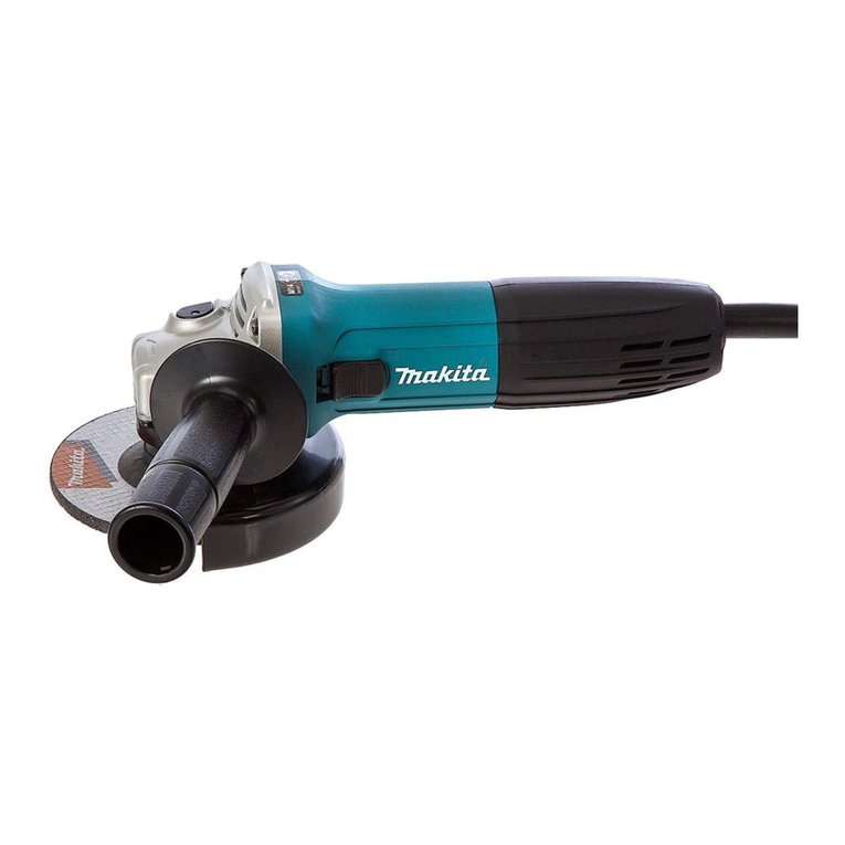
Makita 9564PC Manual

Model No.
Description
PRODUCT
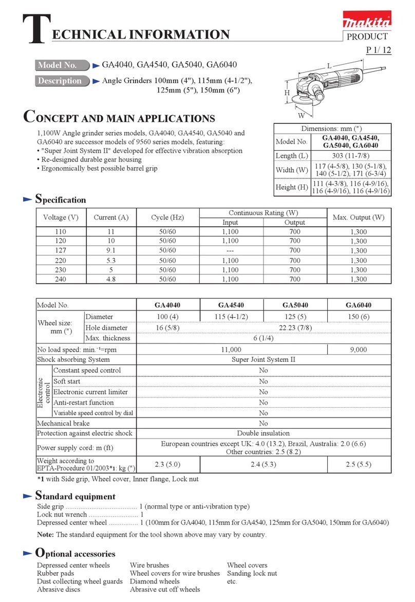
CONCEPT AND MAIN APPLICATIONS
P 1/ 10
Specification
Standard equipment
Note: The standard equipment for the tool shown above may differ from country to country.
9564PC/ 9565PC/ 9566PC
9564PCV/ 9565PCV/ 9566PCV
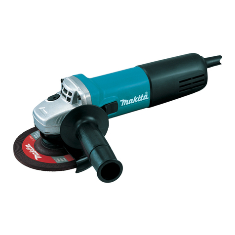
Angle Grinders
115mm (4-1/2")/ 125mm (5")/ 150mm (6")
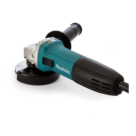
Models 9564PC/ 9565PC/ 9566PC have been developed
as sister tools of 9564C/ 9565C/ 9566C, featuring
paddle type on/off switch.
Models 9564PCV/ 9565PCV/ 9566PCV additionally feature
variable speed control by dial.
Lock nut wrench ................... 1
Depressed center wheel ......... 1 (115 for 9564PC/ 9564PCV, 125 for 9565PC/ 9565PCV, 150 for 9566PC/ 9566PCV)
Cut-off wheel ........................ 1 ( 9566PC for USA)
Side grip ................................ 1
Dimensions: mm (")
Width (W)
Height (H)
Length (L)
Model No. 9564PC
9564PCV
307 (12-1/8)
129 (5-1/8)
103 (4)
9565PC
9565PCV
139 (5-1/2)
9566PC
9566PCV
169 (6-5/8)
L
H
Continuous Rating (W)
Voltage (V) Cycle (Hz) Input Output Max. Output (W)
120
110 13 1,400
---
840 1,80050/60
6.7 1,400 840 2,10050/60
6.4 1,400 840 2,10050/60
6.1 1,400 840 2,10050/60
13 840 2,00050/60
220
230
240
Current (A)
Optional accessories
Anti-vibration grip, Dust cover attachment, Loop handle, Toolless wheel cover
9564PC/ 9564PCV: Accessories for 115mm (4-1/2") angle grinder
9565PC/ 9565PCV: Accessories for 125mm (5") angle grinder
9566PC/ 9566PCV: Accessories for 150mm (6") angle grinder
W
Model No.
No load speed:
min.-1 = rpm
Diameter
Hole diameter
Wheel size:
mm (")
Protection against electric shock
Power supply cord: m (ft)
Net weight: kg (lbs)
9564PC/ 9564PCV 9565PC/ 9565PCV 9566PC/ 9566PCV
115 (4-1/2)
Australia, Brazil, Chile: 2.0 (6.6), Other countries: 2.5 (8.2)
1.9 (4.2)
11,500/ 2,800 - 11,500
125 (5) 150 (6)
9,200/ 4,000 - 9,200
10,000/ 4,000 - 10,000
Double insulation
22.23 (7/8)
Super Joint System (SJS) Yes
Constant speed control Yes
Soft start Yes
Electronic current limiter Yes
Variable speed control by dial No/ Yes No/ Yes No/ Yes
China
Other countries
11,000/ 2,800 - 11,000
Electronic
control
TECHNICAL INFORMATION
P 2 / 10
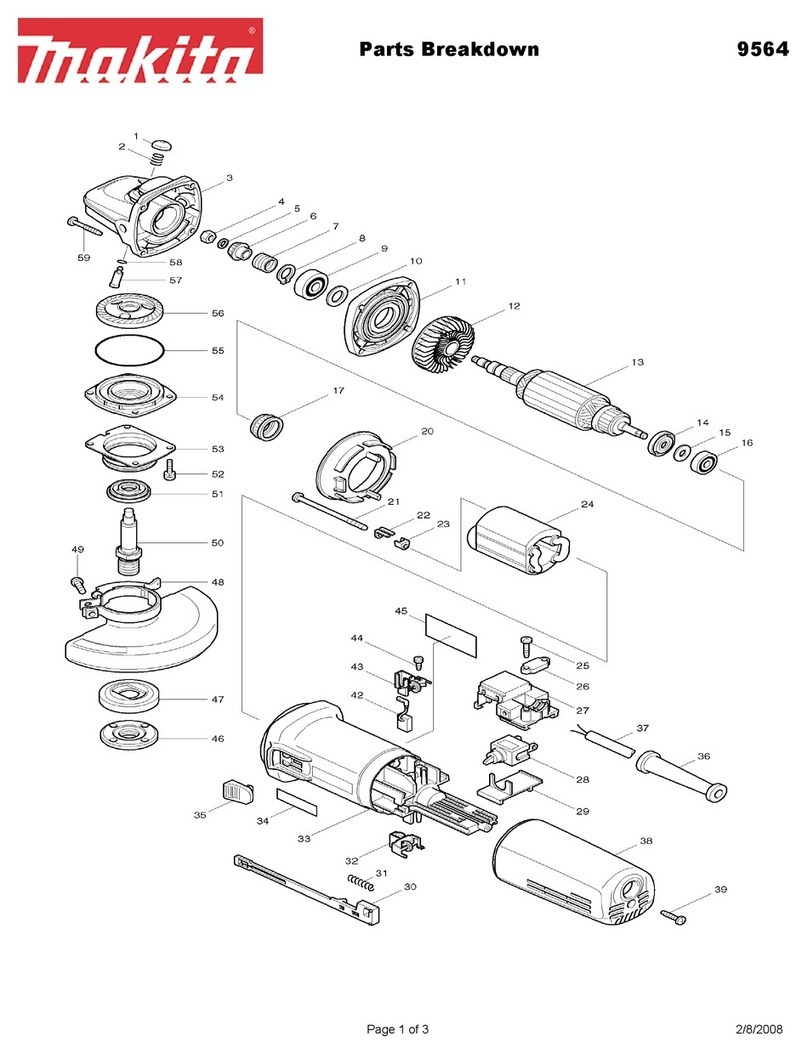
[2] LUBRICATION
[3] DISASSEMBLY/ASSEMBLY
[3] -1. Armature, Spiral Bevel Gear 11
Apply Makita grease SG No.00 to the portions designated with the black triangle, and apply Molybdenum
disulfide lubricant to the portions designated with gray triangle to protect parts and product from unusual abrasion.
[1] NECESSARY REPAIRING TOOLS
CAUTION: Unplug the machine and remove the wheel, the wheel cover, the inner flange and
the outer flange from the machine for safety before repair/ maintenance in
accordance with the instruction manual!
Fig. 1
Fig. 2 Fig. 3
Repair
DISASSEMBLY
DescriptionCode No. Use for
Item No. Description Portion to lubricate
1R217 Ring 22 Holding Bearing box when removing Spiral bevel gear 38
Holding Gear housing complete when removing Pin for shaft lock
1R268
1R269
1R291
Spring pin extractor M3 Removing Pin for shaft lock
Removing Ball bearing 627DDW from Armature shaft
Removing / Assembling Retaining ring S-12 from / to Armature shaft
Removing / Assembling
Bearing retainer
Bearing extractor
Retaining ring S and R pliers
1R340 Bearing retainer wrench
1R350 Ring 60
8
36
3
6
8
Gear housing complete
Spiral bevel gear 11
Lock spring 12
Gear room: Apply approx. 15g.
Inside
Shift the tail of Spiral spring
from the top of Carbon brush to
the side notch of Brush holder.
Disconnect the Carbon brush from
Armature's commutator by pulling.
Rear cover (L) Rear cover (R)
4x40 Tapping screw: 3 pcs.
Disassemble Rear cover (L and R)
from Motor housing by unscrewing
4x40 Tapping screws.
(1) Disconnect Carbon brush from Armature's commutator as illustrated in Figs. 2 and 3.

P 3 / 10
[3] DISASSEMBLY/ASSEMBLY
[3] -1. Armature, Spiral Bevel Gear 11 (Cont.)
Repair
DISASSEMBLY
Gear housing
complete
Gear housing
complete
Gear housing
cover
Gear housing
cover
Gear housing cover
Gear housing cover
Armature
1R269
Spiral bevel gear 11
4x28 Tapping
screw: 4pcs.
After removing Tapping screws, separate Gear housing complete with
Gear housing cover from Motor housing.
Armature comes with Gear housing cover.
Motor housing
Remove Spiral bevel gear 11
with 1R269.
Remove Armature with arbor press.
Remove Retaining ring S-12
with 1R291.
Hex nut M6 Wrench 10
Remove Hex nut M6 by turning
it counterclockwise. And take off
Flat washer 6.
Flat washer 6
Spiral bevel gear 11
Lock Spring 12
Retaining ring S-12
Remove Lock spring 12
by turning it counterclockwise.
1R291
Armature
Fig. 4 Fig. 5
Fig. 6 Fig. 7 Fig. 8
Fig. 9
(2) Disassemble Spiral bevel gear 11 and Armature in the order of Figs. 4 to 9.

P 4 /10
[3] DISASSEMBLY/ASSEMBLY
[3] -1. Armature, Spiral Bevel Gear 11 (Cont.)
Repair
DISASSEMBLY
ASSEMBLY
Remove three tabs of Self lock 6
from Armature shaft with
tweezers, and remove Self lock 6
from Armature.
Remove Magnet sleeve,
Wave washer 6 and
Labyrinth rubber ring 22 .
Remove Ball bearing
627DDW with 1R269.
Remove Flat washer 7
and Insulation washer.
Self lock 6
Tweezers
Magnet sleeve
Wave washer 6
Labyrinth
rubber
ring 22
Ball bearing
627DDW
1R269
Flat
washer 7
Insulation
washer 7
(3) The parts on the commutator end of Armature are disassembled as illustrated in Fig. 10.
(1) Assemble Insulation washer and Flat washer 7 to Armature shaft. And then, assemble Ball bearing 627DDW with
Arbor press. And cover Ball bearing 627DDW with Labyrinth rubber ring 22.
(2) If Wave washer 6 is assembled as illustrated in Fig. 11, Magnet sleeve can not be stabilized on Armature shaft.
Therefore, assemble Wave washer 6 as the left illustration in Fig. 12, and then assemble Magnet sleeve and Self lock 6
to Armature's commutator end.
Fig. 10
Fig. 11 Fig. 12
Wrong
Wave washer 6 can
not press Magnet
sleeve toward Self
lock 6 to stabilize
Magnet sleeve.
Press down Self lock 6 until
Wave washer 6 gets flat.
Magnet sleeve is
stabilized between
Self lock 6 and
Wave washer 6
by the reaction
of Wave washer 6.
Return tabs of Self lock 6 to their
normal shape before assembling.
Correct
Wave washer 6
Magnet sleeve
Self lock 6
(3) As for assembly of the drive end of Armature, do the reverse of the disassembling steps. Refer to Figs 4 to 9.

P 5 / 10
[3] DISASSEMBLY/ASSEMBLY
[3] -2. Spiral Bevel Gear 38 and Ball Bearing 6201DDW
Repair
DISASSEMBLY
M4x16 Hex socket head bolt
with adhesive: 4 pcs.
Spiral bevel gear 38
can be removed.
Remove M4x16 Hex socket
had Bolts. And then remove
Bearing box from Gear housing
complete.
Remove Spindle with Arbor
press.
Strike the specific position with Plastic
hammer as illustrated below, if it is
difficult to remove the Bearing box by
hand in the step of Fig.13.
Bearing
box
Bearing box
Spiral bevel gear 38 and Ball bearing 6201DDW are disassembled as illustrated in Figs. 13 to 17(A).
Spiral bevel
gear 38
Bearing
retainer
Bearing
retainer
Ball bearing 6201DDW
Ball bearing
6201DDW
Ball bearing
6201DDW
Bearing box
1R217
1R041
1R340
Fit the protrusions of 1R340 into the groove of Bearing retainer.
And turn it counterclockwise. Now Bearing retainer is removed
from Bearing box.
Spindle
Labyrinth ring
Fig. 14Fig. 13
Fig. 15 Fig. 16
Fig. 17 Fig. 17A
Remove Ball bearing 6201DDW by striking
Bearing box straight down against flat surface
of work bench.
If cannot be removed, use arbor press and a round bar for arbor
of an appropriate size as illustrated below.
Fix Bearing retainer with Vise
and 1R041.
Fig. 13A

P 6 / 10
[3] DISASSEMBLY/ASSEMBLY
[3] -2. Spiral Bevel Gear 38 and Ball Bearing 6201DDW (Cont.)
Repair
DISASSEMBLY
ASSEMBLY
Note: M4x16 Hex socket head bolts in Fig.13 are adhesive bolts. Apply ThreeBond 1321B/1342 or Loctite 242 to their
threaded portion before driving them.
ASSEMBLY
Do the reverse of the disassembling steps. Refer to Figs. 13 to 17(A).
(1) Disassemble Gear housing complete from Motor housing. (Fig. 4)
(2) Remove Bearing box from Gear housing complete. (Fig. 13 or Fig. 13A)
(3) Disassemble the parts for Shaft lock mechanism as illustrated in Fig. 18 and 19.
[3] -3. Shaft Lock Mechanism
Applying 1R268 to Pin through the small hole on Pin cap,
strike 1R268 with Plastic hammer.
Now Pin comes out from Gear housing complete.
Release 1R268 from Pin cap carefully so
that Pin cap is not slung by Compression
spring 8.
Pin
Pin cap
Do not reuse Pin cap.
Removing Pin causes damages to the inside
surface of Pin cap.
Pin cap
Pin cap
Compression spring 8
1R268
1R350
Fig. 18 Fig. 19
Fig. 20 Fig. 21
(1) Be sure to use a new Pin cap for replacement and to remove all the plastic dust on Pin. (Fig. 20)
(2) Assemble the Parts for Shaft lock mechanism as illustrated in Fig. 21.
Plastic dust
O ring 6
Pin
Pin
Assemble Pin cap by pressing it to Pin.Insert Pin through the hole
of Gear housing complete.
Pin cap
Do not forget to assemble
Compression spring 8.
Compression spring 8

Switch
C
Circuit diagram
P 7 /10
White
Blue
Color index of lead wires' sheath
Black
Red
Brush holder
Field
Brush holder
Controller
Cord clamp
Noise
suppressor
Power supply cord
Connecting with
Receptacle / Tab
A
Lead wire A: Brown for some countries, instead of Black
Lead wire B: Blue for some countries, instead of White
Lead wire C: White for some countries, instead of Blue
B
*(without Pre-set dial: 9564PC , 9565PC, 9566PC)
* Pre-set dial
Fig. D-1

Wiring diagram
P 8 / 10
Controller's lead
wire (black);
to Switch terminal 1
Lead wire holder
of Controller
Fix Controller's Lead wire (black) and that of (blue or white) with the Lead wire holder of Controller,
putting them under Field lead wire ( black) and that of (red).
Lead wire holder of
Motor housing
Controller's lead
wire (blue or white);
to Switch terminal 2
Controller's Lead wire (red)
to Receptacle/Tab of Field
lead wire (red)
Controller
Receptacle/Tab
Pre-set dial
b) Field lead
wire (red)
c) Field lead
wire (black)
a) Controller's lead
wire (red)
a) Fix Controller's lead wire (red) with
Lead wire holders Aand B.
b) Fix Field lead wire (red) with
Lead wire holders Cand D.
c) Fix Field lead wire (black) with
Lead wire holder D.
And connect to Brush holder.
Lead wire
holder D
Lead wire
holder C
Lead wire
holder B
Lead wire
holder A
Pin
Pass the following Lead wires
between Pin and Lead wire holder B.
* Field lead wire (red)
* Controller's lead wire (black)
* Controller's lead wire (blue or white)
*(without Pre-set dial:
9564PC , 9565PC,
9566PC)
Controller
Fig. D-2
( Left side of Motor housing)

Wiring diagram
P 9 / 10
Controller
Rib A
Rib B
Field lead wire (black)
Pass Field lead wire (black)
on Rib A.
And connect to Brush holder.
Field lead wire (red)
Pass Field lead wire (red) between
Controller and Rib B.
Lead wire
holder D'
Fix Field lead wires (black and red) with
Lead wire holder D'.
Fig. D-3
( Right Side of Motor Housing)

Wiring diagram
P 10 / 10
Connect Insulated
connectors to Switch,
and vend the Insulated
connecters as illustrated
right in order to push
the lead wires into the
space between ribs.
Put Lead wires of Power supply cord to
the inside of ribs near Switch.
Switch
Switch button
Switch button
Noise suppressor
Noise suppressor
Switch
Fix the following lead wires with the notch of Switch as illustrated above.
* Controller's lead wire (blue or white)
* Controller's lead wire (black)
* Noise suppressor's lead wire (white)
Fix Controller's lead wire (black)
and that of (blue or white) with Lead
wire holder.
Controller's lead wire (blue or white)
Switch
Controller's lead wire (black)
Controller's lead wire (blue or white)
Noise suppressor's lead wire (white)
(Opposite side of Switch Button)
Bottom View of Switch
Fig. D-4
( Belly Side of Motor housing)
Other manuals for 9564PC
10
This manual suits for next models
5
Table of contents
Other Makita Grinder manuals

Makita
Makita DGA701 User manual

Makita
Makita 9564HR User manual

Makita
Makita GA030G User manual

Makita
Makita GA036G User manual

Makita
Makita GD0602 User manual

Makita
Makita GA5080 User manual

Makita
Makita M9514 User manual

Makita
Makita DGA405 User manual

Makita
Makita M9002 User manual

Makita
Makita M9512 User manual

Makita
Makita GA039G User manual

Makita
Makita 9067 User manual

Makita
Makita DGA512ZU User manual

Makita
Makita GA7020R User manual

Makita
Makita GA4593 User manual

Makita
Makita GA5080 User manual

Makita
Makita M9100 User manual

Makita
Makita GA011G User manual

Makita
Makita 9564CVL User manual

Makita
Makita 906 User manual