Makita GA4041 Manual

PRODUCT
P 1/ 14
Model No.
Description
GA4041, GA4541, GA5041, GA6041
Angle Grinders 100mm (4"), 115mm (4-1/2"),
125mm (5"), 150mm (6")
1,100W Angle grinder series models; GA4041, GA4541, GA5041 and
GA6041 are successor models of 9560 series models, featuring:
•"Super Joint System II" developed for effective vibration absorption
• Mechanical brake for powerful braking
• Re-designed durable gear housing
• Ergonomically best possible barrel grip
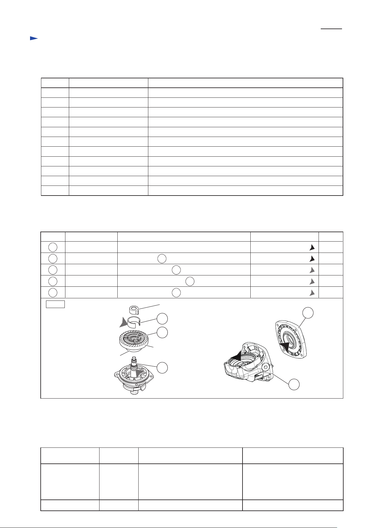
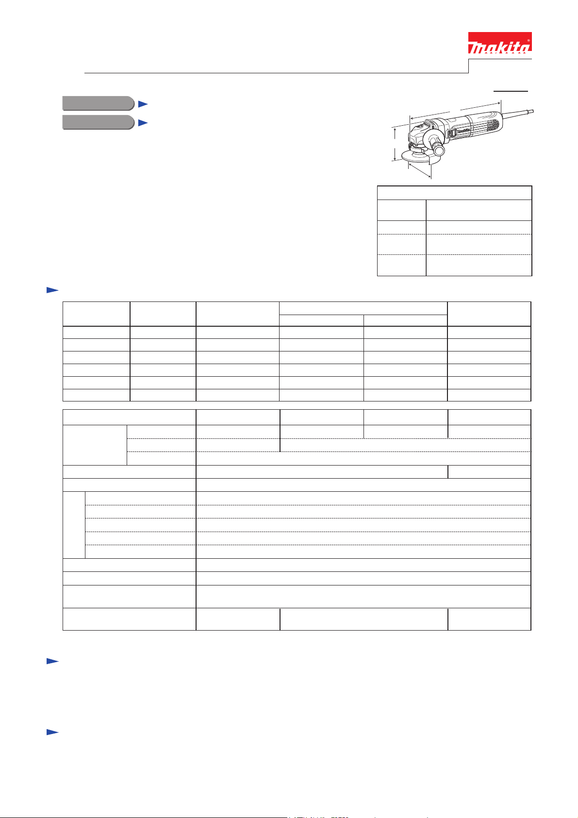
Dimensions: mm (")
Width (W)
Height (H)
Length (L)
Model No.
325 (12-3/4)
GA4041, GA4541,
GA5041, GA6041
117 (4-5/8), 130 (5-1/8),
140 (5-1/2), 171 (6-3/4)
117 (4-5/8), 121 (4-3/4),
121 (4-3/4), 121 (4-3/4)
L
H
W
Standard equipment
Note: The standard equipment for the tool shown above may vary by country.
Side grip .......................................1
Lock nut wrench ..........................1
Depressed center wheel ................1 (100mm for GA4041, 115mm for GA4541, 125mm for GA5041, 150mm for GA6041)
Optional accessories
Depressed center wheels
Rubber pads
Dust collection wheel guards
Abrasive discs
Wire cup brush sets
Wheel covers for wire cup brush sets
Wire bevel brush sets
Wheel covers for wire bevel brush sets
Diamond wheels
Dust collecting wheel guards
Abrasive cut off wheels
Wheel covers
Sanding lock nut
etc.
Specification
Continuous Rating (W)
Voltage (V) Cycle (Hz) Input Output
700
Max. Output (W)
110
120
220
230
240
11
10
5.3
5
4.8
50/60
50/60
50/60
50/60
50/60
1,100
1,100
1,100
1,100
1,100
1,300
1,300
1,300
1,300
1,300
Current (A)
700
127 9.1 50/60
---
1,300700
700
700
700
*1 With Side grip, Wheel cover, Inner flange, Lock nut
Model No.
No load speed: min.ˉ¹=rpm
Diameter
Hole diameter
Wheel size:
mm (")
Protection against electric shock
Power supply cord: m (ft)
Weight according to
EPTA-Procedure 01/2003*1: kg (")
GA4041 GA6041
100 (4) 115 (4-1/2)
European countries except UK: 4.0 (13.2), Brazil, Australia: 2.0 (6.6)
Other countries: 2.5 (8.2)
11,000
150 (6)
Double insulation
22.23 (7/8)16 (5/8)
Max. thickness 6 (1/4)
Shock absorbing System
Mechanical brake
Super Joint System II
No
No
No
No
Constant speed control
Variable speed control by dial
Soft start
Electronic current limiter
Anti-restart function
Electronic
control
No
Yes
GA4541
125 (5)
2.5 (5.5) 2.6 (5.8) 2.7 (6.0)
GA5041
9,000
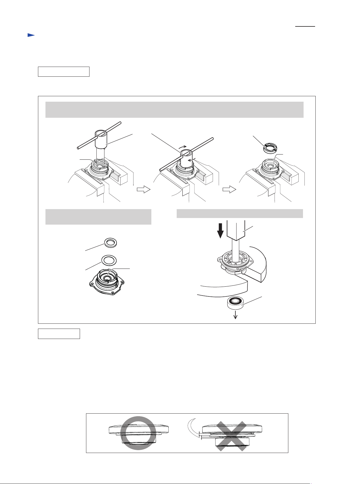
TECHNICAL INFORMATION
CONCEPT AND MAIN APPLICATIONS

P 2/ 14
Repair
Apply Makita grease to the following portions designated with the black triangle and the gray triangle to protect parts
and product from unusual abrasion.
[1] NECESSARY REPAIRING TOOLS
CAUTION: Repair the machine in accordance with “Instruction manual” or “Safety instructions”.
Code No. Description Use for
1R028 Bearing setting pipe 20-12.2 mounting Gear housing cover to Armature
1R045 Gear extractor (Large) separate Armature from Gear housing cover
1R232 Pipe 30 removing Coupling and Ball bearing 6903ZZ from large Spiral bevel gear
1R258 V block supporting Armature and Bearing box
1R268 Spring pin extractor M3 disassembling Shaft lock mechanism
1R269 Bearing extractor removing Ball bearings 627DDW/ 696ZZ from Armature
1R281 Round bar for Arbor 7-50 removing Switch knob from Switch lever
1R286 Round bar for Arbor 12-50 removing large Spiral bevel gear section from Bearing box
1R291 Retaining ring S & R pliers removing Retaining ring S-9
1R340 Bearing retainer wrench removing Bearing retainer 20-33 from Bearing box
1R350 Ring 60 supporting Gear housing when disassembling Shaft lock mechanism
[2] LUBRICATION
Fig. 1
Item No. Description
Gear housing
Gear housing cover
Lubricant AmountPortion to lubricate
Coupling
Spindle
Model No.
GA4041 GA4541C
GA4541 GA5041C
GA5041 GA4543C
GA4041C GA5043C
GA4043C
GA6041
Smaller spiral bevel gear
(on armature shaft)
Larger spiral bevel gear
(on spindle)
10 teeth 38 teeth
9 teeth 41 teeth
Gear room 17g
a little
a little
a little
70
56
Joint sleeve
Note: As listed below, the grinders use different spiral bevel gears, and they are not interchangeable.
Referring to this list, therefore, be sure to use correct gears for replacement.
Spiral bevel gear (large)
Ball bearing 6903ZZ
6
58
58
O-ring 27.5 of 6 Gear housing cover
Drum portion where 58 Coupling contacts
Cylindrical portion where 56 C-type plate contacts
C-type plate a little56 Outer surface where 58 Coupling contacts Makita Grease FA No. 2:
Makita Grease FA No. 2:
Makita Grease SG No. 0:
1
70
[3] DISASSEMBLY/ASSEMBLY
[3] -1. Note in Disassemble (general)
No load
speed: min.ˉ¹
11,000
9,000
6
1

P 3/ 14
Repair
[3] DISASSEMBLY/ASSEMBLY
[3] -2. Armature, Spiral bevel gear [small one]
DISASSEMBLING
(1) Remove Spiral bevel gear (small) from the drive end of Armature as drawn in Fig. 2.
Fig. 2
1. Remove Rear cover by unscrewing
one 4x18 Tapping screw.
4x18 Tapping screw
4x50 Tapping screw
4. Unscrew four Tapping screws. Then separate Gear housing cover from Spacer while applying a slotted
screwdriver to the notch on Gear housing cover on belly side.
Rear cover
2. Shift Spiral spring from
Carbon brush top.
3. Disconnect Carbon brush from
commutator by pulling up.
Note: No need to remove Carbon
brush in this step.
Notch on
Gear housing cover
Gear housing cover
Armature
Gear housing
cover
Compression
spring 33
Brake shoe
holder complete
5. Remove M6 Hex nut to turn it with Wrench 10
counterclockwise. Then, remove Flat washer 6
and small Spiral bevel gear from Armature.
6. Remove Gear housing cover with 1R045.
Then, remove Compression spring 33 and
Brake shoe holder complete.
Caution: Be careful that the cover and the spring
may jump out from Armature side
due to recoil force by the spring.
Flat washer 6
Spiral bevel
gear (small)
M6 Hex nut
1R045
Gear housing cover Gear housing
Spacer
Wrench 10
Armature

P 4/ 14
Repair
DISASSEMBLING
ASSEMBLING
(2) Disassemble the commutator end of Armature as drawn in Fig. 3.
Note: This step is required for the models with electronic control system of GA4041C, GA4043C, GA4541C,
GA4543C, GA5041C, GA5043C.
Fig. 3
1. Pick up three tabs of
Self lock 6 with tweezers
to remove it from Armature.
2. Remove Magnet sleeve,
Wave washer 6 and
Labyrinth rubber ring 22.
3. Remove Ball bearing 627DDW with 1R269. 4. Remove Flat washer 7 and
Insulation washer.
Self lock 6
Tabs
Tweezers
Wave washer 6
Magnet sleeve
Labyrinth rubber ring 22
Ball bearing 627DDW
1R269 Flat washer 7
Insulation washer
(1) Assemble the commutator end of Armature as drawn in Fig. 4.
Note: This step is required for the models with electronic control system of GA4041C, GA4043C, GA4541C,
GA4543C, GA5041C, GA5043C.
Fig. 4
2. Press down Self lock 6 until
Wave washer 6 gets flat.
3. Magnet sleeve is stabilized
between Self lock 6 and
Wave washer 6 by the reaction
force of Wave washer 6.
1. Return tabs of Self lock 6 to their
normal shape before assembling.
Then, mount Wave washer 6 to
the commutator end of Armature.
Note: Be careful of their directions.
Refer to the drawings in Fig. 4.
Wave washer 6
Magnet sleeve
Self lock 6
Wave washer 6
Magnet sleeve
Self lock 6
[3] DISASSEMBLY/ASSEMBLY
[3] -2. Armature, Spiral bevel gear [small one] (cont.)

P 5/ 14
Repair
ASSEMBLING
(2) Assemble the drive end of Armature as drawn in Fig. 5.
Fig. 5
[3] DISASSEMBLY/ASSEMBLY
[3] -2. Armature, Spiral bevel gear [small one] (cont.)
2. Mount Gear housing cover to
Armature to fit the groove of
the cover to Compression
spring 33 and Armature shaft
through Ball bearing 6001LLB.
1. Set Brake shoe holder
complete and Compression
spring 33 to Armature.
3. Supporting Armature section
with 2 pcs. of 1R258, press
Gear housing cover to
Armature section with 1R028.
1R258
1R028
Compression
spring 33
Brake shoe
holder complete
Groove of Gear
housing cover
Compression
spring 33
Ball bearing
6001LLB
Armature
4. Set Spiral bevel gear (small) and Flat washer 6 to Armature shaft.
Then, secure them with M6 Hex nut.
Flat washer 6
Spiral bevel
gear (small)
M6 Hex nut
Wrench 10

P 6/ 14
Repair
ASSEMBLING
(3) Assemble Spacer, Armature section and Gear housing to Motor housing as drawn in Fig. 6.
Fig. 6
[3] DISASSEMBLY/ASSEMBLY
[3] -2. Armature, Spiral bevel gear [small one] (cont.)
1. Set Switch knob to “Lock ON” position so that Switch plate is pushed toward Spacer.
Then, mount Spacer while fitting its groove to Switch plate.
And then, return Switch knob to “OFF” position.
2. Assemble Armature section to Motor housing
while fitting the wings of Brake shoe complete
to the grooves of Spacer.
3. Face the notch to the same side as Name plate
by twisting Gear housing cover.
4. Assemble Gear housing while facing Spindle to the same side
as the notch and Name plate.
Groove of Spacer
Spacer
Wing of
Brake shoe complete
Wing of
Brake shoe complete
Switch plate Switch knob
groove
Notch on
Gear housing cover
Notch on
Gear housing cover
Gear housing cover
Spacer
Name plate
Name plate
Gear housing
Spindle

P 7/ 14
Repair
DISASSEMBLING
Note: The gear and the ball bearings can be replaced without disassembling the motor section.
(1) Remove Ball bearing 696ZZ, Retaining ring S-9, Flat washer 10 and C-type plate from Spindle as drawn in Fig. 7.
Fig. 7
[3] DISASSEMBLY/ASSEMBLY
[3] -3. Spiral bevel gear [large one], Ball bearings 696ZZ/ 6201DDW
1R258
1. Remove four M4x16 Hex socket head bolts, then separate Bearing box section from Gear housing.
Bearing box
section
M4x16 Hex socket head bolt
1R269
2. Remove Ball bearing 696ZZ
with 1R269.
3. Remove Retaining ring S-9
with 1R291.
4. Remove Flat washer 10.
Then, remove C-type plate.
5. Receive Bearing box with 1R258
and remove Spindle by pressing it
with Arbor press.
6. Joint sleeve can be removed.
Ball bearing
696ZZ Retaining
ring S-9
Flat washer 10
C-type plate.
7. Using 1R291, remove Retaining
ring R-26 from the inside of
Lead flange.
Then, separate Lead flange
from Spindle .
Lead flange
Spindle
Retaining
ring R-26
Joint sleeve
Arbor press
1R258 1R258 1R258
Spindle
1R291

P 8/ 14
Repair
DISASSEMBLING
(2) Disassemble large Gear section from Bearing box as drawn in Fig. 8.
Fig. 8
[3] DISASSEMBLY/ASSEMBLY
[3] -3. Spiral bevel gear [large one], Ball bearings 696ZZ/ 6201DDW (cont.)
1. Tap Bearing box to shift Flat washer 12
so that the surface is revealed as large as
possible.
Then, put Bearing box on 1R258.
Bearing retainer
Bearing box Flat washer 12
Flat washer 12
2. While applying 1R286 to Flat washer 12 through Bearing
retainer, press it carefully to remove large Spiral bevel gear
section (including Coupling and Ball bearing 6903ZZ)
from Bearing box.
1R286
large
Spiral bevel gear
Ball bearing
6903ZZ
Coupling
Flat washer 12
Coupling
Ball bearing 6903ZZ
large Spiral bevel gear
3. Put large Spiral bevel gear section
on 1R258. Then, apply 1R232 to
Coupling of the gear section.
4. Remove Coupling together with Ball bearing 6903ZZ
from large Spiral bevel gear by pressing 1R232 with Arbor
press. And then, disassemble the bearing from Coupling.
Note: Do not re-use the removed Ball bearing 6903ZZ
because it is damaged in the step of removing Spindle.
1R2581R258 1R2581R258
1R258
1R232
1R232
Arbor press

P 9/ 14
Repair
(3) Disassemble Ball bearing 6201DDW from Bearing box as drawn in Fig. 9.
Fig. 9
ASSEMBLING
Assemble by reversing the disassembly procedure. (Refer to Figs. 9, 8 and 7)
Note: •Do not re-use the removed Joint sleeve. New Joint sleeve has to be mounted.
(Refer to the bottom center illustration in Fig. 7)
• Apply the following thread locker to the thread of M4x16 Hex socket head bolts if the unscrewed bolts are used.
* Three Bond 1342
* Loctite 242
(Refer to the upper left illustration in Fig. 7)
• Coupling, large Spiral bevel gear, Ball bearing 6903ZZ have to be assembled tightly that there is any gaps
among them. See the left illustration in Fig. 10.
Fig. 10
Incomplete assembling causes gaps.
DISASSEMBLING
[3] DISASSEMBLY/ASSEMBLY
[3] -3. Spiral bevel gear [large one], Ball bearings 696ZZ/ 6201DDW (cont.)
1. Clamp Bearing box with Vise. Then, while fitting the claw of 1R340 to the notch of Bearing retainer 20-33,
turn 1R340 clockwise to remove the retainer.
2. Take out Felt ring 17 and Flat washer 21
from Lead flange side of Bearing box.
3. Remove Ball bearing 6201DDW with Arbor press.
1R340
Bearing
retainer 20-33
Bearing
retainer 20-33
Felt ring 17
Arbor press
Felt ring 17
Flat washer 21 Ball bearing
6201DDW
Ball bearing
6201DDW

P 10/ 14
Repair
[3] DISASSEMBLY/ASSEMBLY
[3] -4. Switch Lever
DISASSEMBLING
(1) Remove Rear cover from Motor housing by removing 4x18 Tapping screw. (Fig. 2)
(2) Disassemble Switch lever and Switch knob from the machine as drawn in Fig. 11.
Fig. 11
Fig. 12
ASSEMBLING
(1) Insert Switch lever into Motor housing. And push it until the loop portion comes into sight through Switch knob
assembling hole on Motor housing. Refer to the right and center illustration in Fig. 11.
(2) Assemble Switch knob to Switch lever as drawn in Fig. 12.
1. Make sure that Compression spring 4 is assembled
to Switch lever in advance.
2. Fitting Switch knob to the loop portion of Switch
lever and the claw portion of Switch plate, hold
Switch knob. And then, release Switch lever.
(The hook of Switch knob interlocks with the hole
of Switch lever when Switch lever is pushed back
to OFF position by Compression spring 4.)
Switch knob
Switch lever
Switch plate
Switch lever
Compression spring 4
3. Bending Switch lever, pull out
Switch lever from Motor housing.
1. While locking Switch knob
with 1R281, strongly push
Switch lever in a direction
designated with black arrow.
2. Switch lever is disconnected from
the locking claw of Switch knob.
Then, remove Switch knob.
1R281
Switch lever
Switch knob
Switch lever

P 11/ 14
Repair
[3] DISASSEMBLY/ASSEMBLY
[3] -5. Switch Block
[3] -6. Switch
DISASSEMBLING
After removing Switch lever (Refer to Fig. 11), separate Switch block from Motor housing as drawn in Fig. 13.
After removing Switch lever (Refer to Fig. 11), remove Switch from Switch block as drawn in Fig. 14.
Fig. 13
Insert Slotted screwdriver into the gap between Switch
block and Motor housing, remove Switch block from
Motor housing by twisting the screwdriver.
Fig. 14
Fig. 15
Switch block
Controller
DISASSEMBLING
[3] -7. Brush Holder
DISASSEMBLING
Insert Slotted screwdriver into the gap between Switch and Switch block.
While fitting the tip of the screwdriver to the side groove of Switch,
remove Switch by prying it off.
Remove 3x10 Tapping screw. Then, insert Slotted screwdrivers into the gap between Motor housing
and Brush holder’s plastic portion. And then, disassemble Brush holder by prying them off.
Brush holders can be disassembled as drawn in Fig. 15.
Brush holder
Slotted screwdriver
Switch
Slotted screwdrivers
Slotted screwdriver

P 12/ 14
Repair
[3] DISASSEMBLY/ASSEMBLY
[3] -8. Shaft Lock
DISASSEMBLING
While applying 1R268 to Shoulder pin 6 through the small hole
on Pin cap, tap 1R268 with a hammer.
Now, Shoulder pin 6 comes out from Gear housing complete.
Release 1R268 from Pin cap carefully
so that Pin cap will not pop out by
Compression spring 8.
Shoulder pin 6
Pin cap
Note: Do not re-use removed Pin cap
because removal one damages
the inside surface of the cap,
producing plastic dust.
Pin cap
Pin cap
Compression
spring 8
1R268
1R350
Fig. 16 Fig. 17
(1) Disassemble Bearing box section as drawn in the upper two illustrations in Fig. 7.
(2) Disassemble Shaft lock mechanism as drawn in Figs. 16 and 17.
Fig. 18 Fig. 19
(1) Be sure to use a new Pin cap for replacement and to remove all the plastic dust on Shoulder pin 6. (Fig. 18)
(2) Assemble the Parts for Shaft lock mechanism as drawn in Fig. 19.
Plastic dust
O Ring 4
Shoulder pin 5 Shoulder
pin 6
Pin cap
Compression
spring 8
ASSEMBLING
2. Assemble new Pin cap by pressing
it to Shoulder pin 6.
Note: Do not forget to assemble
Compression spring 8.
1. Insert Shoulder pin 6 through
the hole of Gear housing
complete.

P 13/ 14
Circuit diagram
Color index of lead wires' sheath
with Controller
GA4041C, GA4043C, GA4541C, GA4543C, GA5041C, GA5043C
Blue
Fig. D-1A
Brown
Switch
Controller
Noise suppressor* is installed
in Switch block.
*Noise suppressor is not used
for some countries.
Field Brush holder
Noise
suppressor
7
Black lead wire is used
for some countries.
White lead wire is used
for some countries.
8
6
1
45
2
3
Switch block
without Controller
Field Brush holder
57
Switch
Noise
suppressor
GA4041, GA4541, GA5041, GA6041
Fig. D-1B
Color index of lead wires' sheath
Blue Brown
Switch block
Noise suppressor* is installed
in Switch block.
*Noise suppressor is not used
for some countries.
Black lead wire is used
for some countries.
White lead wire is used
for some countries.
8
6
1
4
2
3

P 14/ 14
Wiring diagram
Fig. D-2
Wiring of Lead wires of Power supply cord
Put Lead wires of Power supply cord
into this place designated with gray color.
This manual suits for next models
3
Table of contents
Other Makita Grinder manuals

Makita
Makita DGD800 User manual

Makita
Makita GD0800C User manual

Makita
Makita GA7030 User manual

Makita
Makita DGA408 User manual

Makita
Makita 9627 User manual

Makita
Makita DGA454 User manual

Makita
Makita 9560C User manual

Makita
Makita GA7064 User manual

Makita
Makita 906 User manual

Makita
Makita GA7070 User manual

Makita
Makita 9218SB Quick start guide

Makita
Makita DGA404 Manual

Makita
Makita 9558NB Quick start guide

Makita
Makita 9501B User manual

Makita
Makita GA4541R User manual

Makita
Makita 9005BY User manual

Makita
Makita GA4030R User manual

Makita
Makita GA5020 User manual

Makita
Makita 9523NB User manual

Makita
Makita 9556NB User manual